Fiber Rotators for Multi-Axis Flexure Stages

- Bare Fiber and Fiber Chuck Rotators
- Ideal for PM Fibers
- Compatible with a Wide Range of
Positioning Stages or Accessories
HFR001
RMS-Threaded
Fiber Chuck Rotator
HFR007
High Precision Fiber Rotator
Quick-Load Bare Fiber
OVERVIEW
| Other Bare Fiber Mounts | ||||
|---|---|---|---|---|
| Post Mountable or SM Threaded |
Post Mountable with Vacuum Port |
Flexure Stage Compatible | ||
| V-Mounts | Fiber Block | Clamps | Chucks | Rotators |
Features
- Ideal for Angle-Sensitive Setups Involving PM Fiber
- Smooth, Continuous 360° Rotation
- Options for Bare Fiber and Fiber Chucks
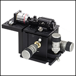
Both the HFR007 High Precision Bare Fiber Rotator and the HFR001 Fiber Chuck Rotator are designed for continuous rotation of fiber in angle-sensitive setups. Either of these rotators can be combined with our line of Multi-Axis Flexure Stages to form orientation-dependent fiber launch systems. Thorlabs also offers a line of complete fiber launch assemblies configured for SM and PM fiber.
Flexure stage mounts can be fixed in position using AMA010(/M) mounting cleats, which are sold below. Each cleat is designed with one edge milled flat, making it possible to insert or remove a flexure stage mount without removing the clamp. Simply loosen the clamp screw and rotate the flat side of the lock-down clamp inward to release the flexure stage mount.
High-Precision Bare Fiber Rotator
The HFR007 Fiber Rotator readily accepts uncoated fiber with an outer cladding diameter of 125 µm. The fiber is easily loaded into the rotator's V-groove, and a swing arm holds it in place using a strong magnetic force. It features a graduated knob that allows high-precision rotations accurate to approximately 2°, and features a 3 mm wide key on the bottom so that it can be easily mounted onto any of our multi-axis flexure stages.
1/4" Fiber Chuck Rotator
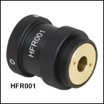
The HFR001 Fiber Chuck Rotator allows smooth rotation of 1/4" fiber chucks, and features RMS-threading (0.800"-36). Three nylon-tipped setscrews hold the fiber chuck in place. It can be attached to any of our multi-axis flexure stages using an HCS013 objective mount.
| Multi-Axis Stage Accessories | |||||||||||
|---|---|---|---|---|---|---|---|---|---|---|---|
 |
 |
 |
 |
 |
 |
 |
 |
 |
 |
 |
 |
| Fiber Mounts |
Fiber Rotators |
Waveguide Mounts |
Diode Mounts |
Fixed Mounts |
Kinematic Mounts |
Top Plates |
Extension Platforms |
Fiber Chucks |
Slide Holders |
Kinematic Platforms |
Adapter Plates |
MULTI-AXIS STAGES
Multi-Axis Stage Selection Guide
Click to Enlarge
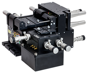
In the above application, a 3-Axis NanoMax flexure stage is aligned in front of a 6-axis stage at the proper 112.5 mm deck height using an AMA554 Height Adapter.
3-Axis Stages
Thorlabs offers three different 3-Axis Stage variations: NanoMax flexure stages, MicroBlock compact flexure stages, and RollerBlock long-travel stages. Each stage features a 62.5 mm nominal deck height. Our NanoMax line of 3-axis stages offers built-in closed- and open-loop piezos as well as modular drive options that include stepper motors, differential drives, or additional piezos. The MicroBlock stages are available with differential micrometer drives or fine thread thumbscrews; these drives are not removable. Finally, our RollerBlock stage drivers can be switched out for any actuator that has a Ø3/8" (9.5 mm) mounting barrel.
4- and 5-Axis Stages
Our 4- and 5-axis stages are ideal for the static positioning of waveguides or complex optical elements with respect to our 3-axis or 6-axis high-performance alignment stages. Thorlabs' 5-axis stages have nominal heights of 62.5 mm or 112.5 mm. The AMA554 Height Adapter can be used to raise the deck height of the 3-axis or 4-axis stages to 112.5 mm for compatibility with our 5-axis MicroBlock or 6-Axis NanoMax Stages.
6-Axis Stages
Thorlabs' 6-Axis NanoMax Nanopositioners are ideal for complex, multi-axis positioning and have a nominal deck height of 112.5 mm. These stages offer a common point of rotation and a patented parallel flexure design that allows all actuators to be coupled directly to the base to minimize any unwanted motion in the system. Built-in closed- and open-loop piezo options are available. A selection of modular drive options allows any axis to be manual or motorized with the option for external piezos. Our units without included actuators are also available in right- or left-handed configurations. To increase the stage height of the 3-axis stages to 112.5 mm, we recommend our AMA554 Height Adapter, shown in the image to the right.
A complete selection and comparison of our multi-axis stages is available below.
3-Axis Stages
| Item # | MAX313D | MAX312D | MAX311D | MAX383 | MAX381 | MAX303 | MAX302 | MAX301 | MBT602 | MBT616D | RB13M | RBL13D | ||||||||
|---|---|---|---|---|---|---|---|---|---|---|---|---|---|---|---|---|---|---|---|---|
| Stage Type | NanoMax Flexure Stages | MicroBlock Compact Flexure Stages |
RollerBlock Long Travel Stages | |||||||||||||||||
| Included Drives | DRV3 Differential Micrometers | DRV208 Stepper Motor Actuators | N/A | Fine Thread Thumbscrews | Differential Micrometers | 148-801ST Micrometer Drives |
DRV304 Differential Micrometers |
|||||||||||||
| Built-in Piezos | N/A | Open Loop |
Closed Loop | N/A | Closed Loop | N/A | Open Loop | Closed Loop | N/A | N/A | ||||||||||
| Travel (X, Y, Z) | 4 mm (0.16") | 13 mm (0.51") | ||||||||||||||||||
| Deck Height (Nominal) | 62.5 mm (2.46") | |||||||||||||||||||
| Optical Axis Height (Nominal) | 75 mm (2.95") | |||||||||||||||||||
| Load Capacity (Max) | 1 kg (2.2 lbs) | 4.4 kg (9.7 lbs) | ||||||||||||||||||
| Thermal Stability | 1 µm/°C | - | ||||||||||||||||||
| Weight | 1.00 kg (2.20 lbs) | 0.64 kg (1.40 lbs) | 0.59 kg (1.30 lbs) | |||||||||||||||||
4-Axis Stages
| Item # | MBT401D MBT401D/M |
MBT402D MBT402D/M |
|
|---|---|---|---|
| Stage Type | 4-Axis Thin-Profile MicroBlock Device Stage | 4-Axis Low-Profile MicroBlock Device Stage | |
| Included Drives | Differential Micrometers | ||
| Built-in Piezos | N/A | ||
| Travel | Horizontal Axis (Y)a | 13 mm (0.51") | |
| Vertical Axis (Z) | 6 mm (0.24") | ||
| Pitch (θy) | ±5° | ||
| Yaw (θz) | ±5° | ||
| Deck Height (Nominal) | 62.5 mm (2.46") | ||
| Optical Axis Height (Nominal) | 75 mm (2.95") | ||
| Load Capacity (Max) | 0.5 kg (1.1 lbs) | ||
5-Axis Stages
| Item # | MBT401D (MBT401D/M) or MBT402D (MBT402D/M) with MBT501 |
PY005 | |
|---|---|---|---|
| Stage Type | 5-Axis MicroBlock Stage System | Compact 5-Axis Stage | |
| Included Drives | Differential Micrometers | 100 TPI Actuators | |
| Built-in Piezos | N/A | ||
| Travel | Optical Axis (X) | 13 mm (0.51") | 3 mm (0.12") |
| Horizontal Axis (Y) | 13 mm (0.51") | 3 mm (0.12") | |
| Vertical Axis (Z) | 6 mm (0.24") | 3 mm (0.12") | |
| Pitch (θy) | ±5° | ±3.5° | |
| Yaw (θz) | ±5° | ±5° | |
| Deck Height (Nominal) | 112.5 mm (4.43") | 62.5 mm (2.46")a | |
| Optical Axis Height (Nominal) | 125 mm (4.92") | 75 mm (2.95")a | |
| Load Capacity (Max) | 0.5 kg (1.1 lbs) | 0.23 kg (0.5 lbs) | |
6-Axis Stages
| Item # | MAX601D MAX601D/M |
MAX602D MAX602D/M |
MAX603D MAX603D/M |
MAX681 MAX681/M |
MAX682 MAX682/M |
MAX683 MAX683/M |
MAX607 MAX607/M MAX607La MAX607L/Ma |
MAX608 MAX608/M MAX608La MAX608L/Ma |
MAX609 MAX609/M MAX609La MAX609L/Ma |
|
|---|---|---|---|---|---|---|---|---|---|---|
| Stage Type | 6-Axis NanoMax Flexure Stage | |||||||||
| Included Drives | DRV3 Differential Micrometers | DRV208 Stepper Motor Actuators | N/A | |||||||
| Built-in Piezos | N/A | Open Loop | Closed Loop | N/A | Open Loop | Closed Loop | N/A | Open Loop | Closed Loop | |
| Travel | X, Y, Z | 4 mm (0.16") | ||||||||
| θx, θy, θz | 6° | |||||||||
| Deck Height (Nominal) | 112.5 mm (4.43") | |||||||||
| Optical Axis Height (Nominal) | 125 mm (4.92") | |||||||||
| Load Capacity (Max) | 1.0 kg (2.2 lbs) | |||||||||
High Precision Bare Fiber Rotator


Click to Enlarge
Basic Structure of a Typical
Optical Fiber
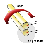
- 10 µm Maximum Eccentricity Over 360° Range
- Graduated Knob (5° Increments)
- Easy-to-Load V-Groove Design
- Swing Arm with Magnetic Clamping Force
- Clamps on Fiber Cladding to Minimize Offset Errors
- Accepts Fiber with Ø125 µm Cladding (with Buffer Removed)
- Locking Setscew
The HFR007 Fiber Rotator can rotate a single mode fiber about the center of the fiber core with a maximum eccentricity of 10 µm when rotated through 360º. Fibers are easily loaded into the V-groove on the fiber rotator and quickly secured by lowering the swing arm that is magnetically held in place. The force used to secure the fiber is adjustable so that the stress induced birefringence can be controlled. The precision fiber rotator allows for top loading of the fiber and provides smooth, continuous 360° rotation.
An engraved graduated knob with 5° increments allows the angular position to be set with an accuracy of ~2°. Once the position is set, a locking screw can be used to fix the angular position of the fiber core.
The precision fiber rotator is pre-adjusted for fibers with an outer cladding diameter of 125 µm (with the buffer coating removed). The coating, sometimes also referred to as a buffer, serves to protect the cladding of glass fibers from particulates that may land on the surface of the fiber, causing it to become brittle. The coating of certain specialized fibers can have optical properties that allow it to act as a second cladding layer. In these cases, the optical properties of the fiber should be considered before stripping off the coating layer.
The HFR007 has a 3 mm wide key on the base, making it compatible with our entire line of flexure stages, roll, pitch and yaw platforms, and fixed platforms and brackets. We also offer bare fiber clamps and chucks, as well as other Fiber Optomechanics. Flexure stage top plates have a central keyway along one or two axes of the stage. This keyway allows all the flexure stage accessories to be accurately placed along the central axis of the stage so that only fine adjustments need to be made to the optical alignment of the system when an accessory is removed and then replaced.

Click to Enlarge
HFR007 Clamping Bare Fiber (Left) and Showing Alignment V-Groove (Right)
| Specification | Value |
|---|---|
| Rotation Range | 360° |
| Compatible Fiber | Ø125 µm Cladding (with Buffer Removed) |
| Maximum Eccentricity | 10 µm |
| Adjustment Accuracy | ~2° |
| Graduated Scale Increment | 5° |
Part Number | Description | Price | Availability |
|---|---|---|---|
HFR007 | Fiber Rotator for Bare Fiber with 125 µm Cladding Diameter | $257.77 | 3 Weeks |
1/4" Fiber Chuck Rotator, RMS Threaded

Click to Enlarge
| Specification | Value |
|---|---|
| Rotation Range | 360° |
| Maximum Eccentricity | <20 µm |
| Mounting Thread | RMS |
| Compatible Objective Mounts | HCS013 |
- Smooth, Low-Friction Fiber Rotator
- Designed for 1/4" Fiber Chucks
- RMS-Threaded (0.800"-36) Mounting Feature Enables Incorporation into Existing Mounts
- Three M3 Nylon-Tipped Setscrews Secure the Fiber Chuck
The HFR001 Fiber Chuck Rotator rotates a standard 1/4" fiber chuck, such as the HFC005, continuously over 360°. The fiber chuck is secured by tightening the M3 nylon-tipped setscrews with a 1.5 mm hex key. The HFR001 has an external RMS thread, which when mounted in an HCS013 microscope objective mount, can be secured to the top plate of one of our multi-axis flexure stages or fixed brackets.
The phosphor-bronze and PTFE bearing in the fiber chuck rotator provides smooth, low-friction rotation for precise angular orientation of a polarization-maintaining fiber. The lateral offset during rotation is typically less than 20 µm; this relatively small offset allows a single mode fiber at Ø1.5 µm to be rotated by about 90° before requiring compensation with the Y and Z adjustments on the flexure stage. The HFR001 can also be used with the a roll/pitch platform (e.g., AMA027) to launch light into polarization-preserving fibers. This combination provides 360° of initial fiber rotation with 8° of fine rotation.
The photo to the right shows a typical application. The fiber chuck rotator holds the fiber, whose output is aligned with the microscope objective, which is threaded into the objective holder and mounted on a fixed bracket. The HFR001 is held in a HCS013 Objective Holder and mounted to an 3-Axis Flexure Stage.
Please note: the HFC007 fiber chuck should not be used with the HFR001 fiber rotator, as it does not provide sufficient clamping force to prevent rotation of the fiber once placed inside the rotator.
Part Number | Description | Price | Availability |
|---|---|---|---|
HFR001 | 1/4" Fiber Chuck Rotation Mount, RMS Threaded (0.800"-36) | $268.46 | Today |
Accessory Lockdown Clamps

Click for Details
Accessories mounted in close proximity using the AMA110 Mounting Block.
- Secures Components to NanoMax, MicroBlock, or RollerBlock Stages
- Cleats for Mounting Single Components
- Mounting Blocks and Clamps for Close Proximity Mounting of Multiple Components
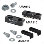
The AMA010(/M) Cleats have a flat milled along one side. To lock an accessory along the center alignment groove, rotate the cleat so that the flat is facing the groove. Place the accessory into the groove between the cleats, rotate the cleat so that the rounded edge covers the edge of the mount, and lock down the 6-32 (M3) locking screw and washer. The cleats can be rotated without needing to remove the locking screws. See the animation to the right for details. The included screws are 5/16" (8 mm) long and are used with a 3/32" (2.5 mm) hex key.
For mounting multiple components in close proximity, we offer the AMA110 mounting blocks. These mounting blocks feature a line of nylon-tipped setscrews to secure components, and allow for easy repositioning and very close mounting. The blocks are secured via two holes and are supplied with either 6-32 or M3 cap screws.
The AMA111 Narrow Device Mounting Clamps offer an alternative solution when devices need to be mounted close together. They are secured using an M3.5 or M3 washer and a 6-32 or M3 cap screw, compatible with a 7/64" or 2.5 mm hex key, respectively.
Part Number | Description | Price | Availability |
|---|---|---|---|
AMA010/M | Cleats with M3 Locking Screws, Qty. 15 | $44.54 | Today |
AMA110/M | Optic Mounting Block, Qty. 2, Metric | $60.38 | Today |
AMA111 | Narrow Device Mounting Clamps, Qty. 2 | $31.49 | Today |
AMA010 | Cleats with 6-32 Locking Screws, Qty. 15 | $44.54 | Today |
AMA110 | Optic Mounting Block, Qty. 2 | $60.38 | Today |

