

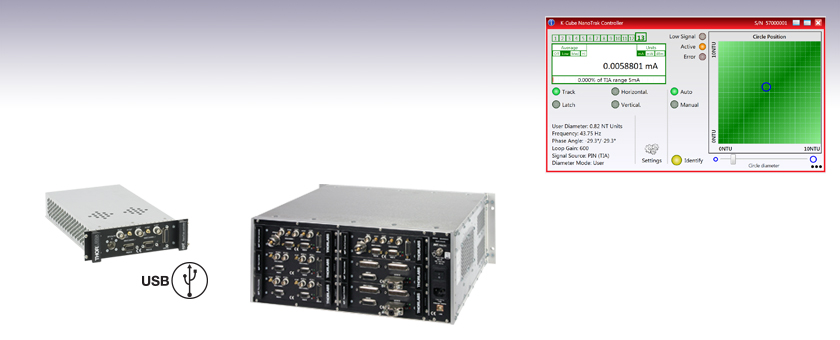
Rack System NanoTrak® Active Auto-Alignment Module
- Advanced Active Alignment
- High-Voltage Piezo Output Channels for Precise Positioning
- IR (InGaAs) Detector Included
- Visible (Si) Detector Available Separately
MNA601/IR
Rack Module
Application Idea
MNA601/IR Module in MMR601 Rack (Back View)
Full Suite of Software Support Tools Included
OVERVIEW
Applications
- Fiber-to-Fiber Active Alignment
- Fiber-to-Free-Space Active Alignment
- Optical Device Alignment
- Waveguide Characterization
- Fiber Characterization and Testing
- Fiber Pigtailing of Active and Passive Devices
- Maintain High Power Throughput to an Entire Optical Setup
| Rack System Motion Control Modules |
|---|
| 2-Channel Piezo Control Module |
| 2-Channel Stepper Motor Controller Module |
| 2-Channel NanoTrak® Auto-Alignment Module |
| 2-Channel Brushless DC Motor Controller Module |
| USB Motion Control 19" Rack Chassis |
| All Thorlabs' Rack System Modules require the use of the APT™ MMR601 or MMR602 Rack System Enclosure. Independent operation of the modules outside the enclosure is not possible. |
Features
- Active Alignment System with Advanced Light Search Algorithm
- Tracking Feature Maintains Optimum Throughput Indefinitely
- Latch Mode to Maintain Alignment Stability over Time
- MNA601/IR Module Provides 2-Axis Control
- MMR601 and MMR602 Rack Systems Hold up to 6 Modules
- Two Piezo Actuator Output Channels Provide Closed-Loop Feedback
- IR (InGaAs) Detector & SMB Connector for External Diodes Included
- Visible (Si) Detector Available Separately
- Full Software GUI Control Suite and Support for Third-Party Custom Applications
The modular NanoTrak Auto-Alignment Controller is designed to maximize the power throughput of a fiber-to-fiber or fiber-to-free-space system. By driving a piezo-actuated stage to move the fiber tip in a circular scan pattern, the controller performs a power gradient search to determine the direction of peak power and positions the fiber for maximum throughput. Two high-voltage output channels provide the drive signal for the associated piezo actuators, eliminating the need for external piezo drivers. In combination with a multi-axis, piezo-driven stage, such as our 3-Axis NanoMax and 6-Axis NanoMax stages, a fiber alignment controller creates a complete auto-alignment system. It can be fully integrated into a rack system that is comprised of a selection of our plug-ins: brushless motor controllers, piezoelectric controllers, stepper motor controllers, and this NanoTrak autoalignment module.
USB connectivity provides easy 'Plug-and-Play' PC-controlled operation with the Kinesis® software package, which features new .NET controls that can be used by third-party developers working in the latest C, C#, LabVIEW™ or any .NET compatible languages to create custom applications. For more details, please see the Motion Control Software, Kinesis Tutorials, and APT Tutorials tabs.
The initial coupling of light from one device (e.g. fiber) to another involves searching a multidimensional space until a signal is detected. The NanoTrak support software offers a series of motor search algorithms for this first light detection. Although used primarily for aligning optical fibers and integrated optical devices, the NanoTrak is ideal for automating just about any labor intensive alignment tasks such as waveguide characterization, fiber pigtailing of active and passive devices, as well as a multitude of other R&D applications.
The NanoTrak module is supplied with an InGaAs detector (item # NTA007) for infrared (900 - 1700 nm) wavelengths and a PIN diode SMB input for use with external detector heads. A Si detector (item # NTA009) for visible (320 - 1100 nm) wavelengths is available separately as detailed below.
Cabling
Cables for connecting actuators or stages to the controller are shipped with the actuators or stages, not the controller. If you need help identifying the appropriate replacement cable, please contact Tech Support.
| NanoTrak® Automated Fiber Alignment Controllers | ||
|---|---|---|
| K-Cube™ 2-Channel Controllers | Benchtop 2-Channel Controller | Modular 2-Channel Rack System Module |
SPECS
Module Specifications
| Signal Measurement | |
|---|---|
| PIN Photodiode | |
| Mechanical Connector | SMB Male |
| Photocurrent Range | 1 nA to 10 mA |
| Optical Connector | FC/PC |
| NanoTraking | |
| Circle Scanning Frequency | 1 to 300 Hz |
| Circle Position Range | <1% to >99% MPE |
| Circle Diameter Adj. Modes | Automatic and Manual |
| Signal Phase Compensation | ±180° |
| Piezoelectric Input/Output | |
| Number of Piezo Channels | 2 |
| HV Output Connectors | |
| Connector Type | SMC Male |
| Voltage Output | 0 to 75 VDC/Channel |
| Voltage Stability | 100 ppm over 24 Hours |
| Noise | <3 mV (RMS) |
| Output Current | 500 mA/Channel |
| Analog Output Monitors | |
| Connector Type | BNC |
| Voltage Range | 0 to 10 VDC |
| Strain Gauge Position Feedback | |
| Connector Type | 9-Pin D-Type Female |
| Feedback Type | AC |
| Other Input/Output | |
| Optical Power Monitor | |
| Connector Type | BNC |
| Voltage Range | 0 to 10 VDC |
| Ext Signal In Input | |
| Connector Type | BNC |
| Voltage Range | 0 to 10 VDC |
| User Control | |
| Connector Type | 26-Pin HD D-Type Female |
| Isolated Digital Inputs | 4 off TTL |
| Isolated Digital Outputs | 4 off TTL |
| Trigger Input | 1 off TTL |
| Trigger Output | 1 off TTL |
| Potentiometer Channel Ctrl Input | 1-10 k (Each Channel) |
| Analog Channel Output Monitors | 0 to 10 VDC (Each Channel) |
| General | |
| Dimensions (W x D x H) | 190 mm x 270 mm x 50 mm |
| Weight | 1.5 kg (3.3 lbs) |
Optical Detector Specifications
| Item # | NTA009a | NTA007a |
|---|---|---|
| Detector Type | Si | InGaAs |
| Operating Wavelength | 320 - 1000 nm | 900 - 1700 nm |
| Active Area | Ø0.8 mm | Ø0.12 mm |
| Fiber Input | FC/PC | |
| Rise Time | 100 ps @ 12 V | |
| NEP | 1.5 x 10⁻¹⁵ W/√Hz | 4.5 x 10⁻¹⁵ W/√Hz |
| Dark Current | 0.01 nA @ 10 V | 0.05 nA @ 5 V |
PIN DIAGRAMS
NanoTrak® Controller
D-type Female
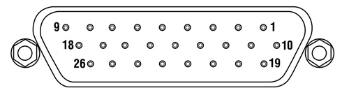
| Pin | Description | Return | Pin | Description | Return | Pin | Description | Return |
|---|---|---|---|---|---|---|---|---|
| 1 | DIG I/P 1a | 19 | 10 | DIG O/P 1a | 19 | 19 | Isolated Groundb | - |
| 2 | DIG I/P 2a | 19 | 11 | DIG O/P 2a | 19 | 20 | Ext Trigger I/P | 22 |
| 3 | DIG I/P 3a | 19 | 12 | DIG O/P 3a | 19 | 21 | Ext Trigger O/P | 22 |
| 4 | DIG I/P 4a | 19 | 13 | DIG O/P 4a | 19 | 22 | Ground | - |
| 5 | Channel 1 RS485 (+) | - | 14 | Channel 2 RS485 (+) | - | 23 | 5 V User O/P (Isolated) | - |
| 6 | Channel 1 RS485 (-) | - | 15 | Channel 2 RS485 (+) | - | 24 | Not Used | - |
| 7 | Not Used | - | 16 | Not Used | - | 25 | Analog Ground | - |
| 8 | Channel 2 10 V O/Pc | 25 | 17 | External Analog I/P CH2 0 - 10 V | 25 | 26 | Signal Power Outd | 25 |
| 9 | Channel 1 10 V O/Pc | 25 | 18 | External Analog I/P CH1 0 - 10 V | 25 |
Piezo Controller
D-type Female
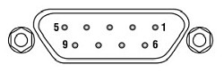
| Pin | Description | Return | Pin | Description | Return | Pin | Description | Return |
|---|---|---|---|---|---|---|---|---|
| 1 | Wheatstone Bridge Excitation | 4 or 6 | 4 | D.C.(+) or Equipment Grounda | - | 7 | D.C.(-) or Actuator ID Signala,b | 4 or 6 |
| 2 | +15Vc | 4 or 6 | 5 | Feedback Signal In | 4 or 6 | 8 | RS485 (-) | 9 |
| 3 | -15Vc | 4 or 6 | 6 | Equiptment Ground | - | 9 | RS485 (+) | 8 |
LV Out
BNC Female
0 to +10V. This output is mirrors HV OUT, 10V being equivalent to 75V on the HV outputs, and can be connected to an oscilloscope to enable the drive signal of the piezo actuator to be monitored.
HV Out
SMC

0 to 75V, 0 to 500mA. Provides the drive signal to the piezo actuator.
Signal In
BNC Female
0 to 10V, 100kΩ load. Used to receive a signal of optical power from an external power meter.
MOTION CONTROL SOFTWARE
Thorlabs offers two platforms to drive our wide range of motion controllers: our Kinesis® software package or the legacy APT™ (Advanced Positioning Technology) software package. Either package can be used to control devices in the Kinesis family, which covers a wide range of motion controllers ranging from small, low-powered, single-channel drivers (such as the K-Cubes™ and T-Cubes™) to high-power, multi-channel, modular 19" rack nanopositioning systems (the APT Rack System).
The Kinesis Software features .NET controls which can be used by 3rd party developers working in the latest C#, Visual Basic, LabVIEW™, or any .NET compatible languages to create custom applications. Low-level DLL libraries are included for applications not expected to use the .NET framework. A Central Sequence Manager supports integration and synchronization of all Thorlabs motion control hardware.
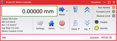
Kinesis GUI Screen
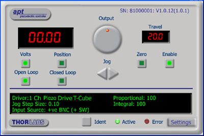
APT GUI Screen
Our legacy APT System Software platform offers ActiveX-based controls which can be used by 3rd party developers working on C#, Visual Basic, LabVIEW™, or any Active-X compatible languages to create custom applications and includes a simulator mode to assist in developing custom applications without requiring hardware.
By providing these common software platforms, Thorlabs has ensured that users can easily mix and match any of the Kinesis and APT controllers in a single application, while only having to learn a single set of software tools. In this way, it is perfectly feasible to combine any of the controllers from single-axis to multi-axis systems and control all from a single, PC-based unified software interface.
The software packages allow two methods of usage: graphical user interface (GUI) utilities for direct interaction with and control of the controllers 'out of the box', and a set of programming interfaces that allow custom-integrated positioning and alignment solutions to be easily programmed in the development language of choice.
A range of video tutorials is available to help explain our APT system software. These tutorials provide an overview of the software and the APT Config utility. Additionally, a tutorial video is available to explain how to select simulator mode within the software, which allows the user to experiment with the software without a controller connected. Please select the APT Tutorials tab above to view these videos.
Software
Kinesis Version 1.14.49
The Kinesis Software Package, which includes a GUI for control of Thorlabs' Kinesis and APT™ system controllers.
Also Available:
- Communications Protocol
Software
APT Version 3.21.6
The APT Software Package, which includes a GUI for control of Thorlabs' APT™ and Kinesis system controllers.
Also Available:
- Communications Protocol
KINESIS TUTORIALS
Thorlabs' Kinesis® software features new .NET controls which can be used by third-party developers working in the latest C#, Visual Basic, LabVIEW™, or any .NET compatible languages to create custom applications.
C#
This programming language is designed to allow multiple programming paradigms, or languages, to be used, thus allowing for complex problems to be solved in an easy or efficient manner. It encompasses typing, imperative, declarative, functional, generic, object-oriented, and component-oriented programming. By providing functionality with this common software platform, Thorlabs has ensured that users can easily mix and match any of the Kinesis controllers in a single application, while only having to learn a single set of software tools. In this way, it is perfectly feasible to combine any of the controllers from the low-powered, single-axis to the high-powered, multi-axis systems and control all from a single, PC-based unified software interface.
The Kinesis System Software allows two methods of usage: graphical user interface (GUI) utilities for direct interaction and control of the controllers 'out of the box', and a set of programming interfaces that allow custom-integrated positioning and alignment solutions to be easily programmed in the development language of choice.
For a collection of example projects that can be compiled and run to demonstrate the different ways in which developers can build on the Kinesis motion control libraries, click on the links below. Please note that a separate integrated development environment (IDE) (e.g., Microsoft Visual Studio) will be required to execute the Quick Start examples. The C# example projects can be executed using the included .NET controls in the Kinesis software package (see the Kinesis Software tab for details).
 |
Click Here for the Kinesis with C# Quick Start Guide Click Here for C# Example Projects Click Here for Quick Start Device Control Examples |
|
LabVIEW
LabVIEW can be used to communicate with any Kinesis- or APT-based controller via .NET controls. In LabVIEW, you build a user interface, known as a front panel, with a set of tools and objects and then add code using graphical representations of functions to control the front panel objects. The LabVIEW tutorial, provided below, provides some information on using the .NET controls to create control GUIs for Kinesis- and APT-driven devices within LabVIEW. It includes an overview with basic information about using controllers in LabVIEW and explains the setup procedure that needs to be completed before using a LabVIEW GUI to operate a device.
 |
Click Here to View the LabVIEW Guide Click Here to View the Kinesis with LabVIEW Overview Page |
|
APT TUTORIALS
The APT video tutorials available here fall into two main groups - one group covers using the supplied APT utilities and the second group covers programming the APT System using a selection of different programming environments.
Disclaimer: The videos below were originally produced in Adobe Flash. Following the discontinuation of Flash after 2020, these tutorials were re-recorded for future use. The Flash Player controls still appear in the bottom of each video, but they are not functional.
Every APT controller is supplied with the utilities APTUser and APTConfig. APTUser provides a quick and easy way of interacting with the APT control hardware using intuitive graphical control panels. APTConfig is an 'off-line' utility that allows various system wide settings to be made such as pre-selecting mechanical stage types and associating them with specific motion controllers.
APT User Utility
The first video below gives an overview of using the APTUser Utility. The OptoDriver single channel controller products can be operated via their front panel controls in the absence of a control PC. The stored settings relating to the operation of these front panel controls can be changed using the APTUser utility. The second video illustrates this process.
APT Config Utility
There are various APT system-wide settings that can be made using the APT Config utility, including setting up a simulated hardware configuration and associating mechanical stages with specific motor drive channels. The first video presents a brief overview of the APT Config application. More details on creating a simulated hardware configuration and making stage associations are present in the next two videos.
APT Programming
The APT Software System is implemented as a collection of ActiveX Controls. ActiveX Controls are language-independant software modules that provide both a graphical user interface and a programming interface. There is an ActiveX Control type for each type of hardware unit, e.g. a Motor ActiveX Control covers operation with any type of APT motor controller (DC or stepper). Many Windows software development environments and languages directly support ActiveX Controls, and, once such a Control is embedded into a custom application, all of the functionality it contains is immediately available to the application for automated operation. The videos below illustrate the basics of using the APT ActiveX Controls with LabVIEW, Visual Basic, and Visual C++. Note that many other languages support ActiveX including LabWindows CVI, C++ Builder, VB.NET, C#.NET, Office VBA, Matlab, HPVEE etc. Although these environments are not covered specifically by the tutorial videos, many of the ideas shown will still be relevant to using these other languages.
Visual Basic
Part 1 illustrates how to get an APT ActiveX Control running within Visual Basic, and Part 2 goes on to show how to program a custom positioning sequence.
LabVIEW
Full Active support is provided by LabVIEW and the series of tutorial videos below illustrate the basic building blocks in creating a custom APT motion control sequence. We start by showing how to call up the Thorlabs-supplied online help during software development. Part 2 illustrates how to create an APT ActiveX Control. ActiveX Controls provide both Methods (i.e. Functions) and Properties (i.e. Value Settings). Parts 3 and 4 show how to create and wire up both the methods and properties exposed by an ActiveX Control. Finally, in Part 5, we pull everything together and show a completed LabVIEW example program that demonstrates a custom move sequence.
Part 1: Accessing Online Help
Part 2: Creating an ActiveX Control
Part 3: Create an ActiveX Method
Part 4: Create an ActiveX Property
Part 5: How to Start an ActiveX Control
The following tutorial videos illustrate alternative ways of creating Method and Property nodes:
Create an ActiveX Method (Alternative)
Create an ActiveX Property (Alternative)
Visual C++
Part 1 illustrates how to get an APT ActiveX Control running within Visual C++, and Part 2 goes on to show how to program a custom positioning sequence.
MATLAB
For assistance when using MATLAB and ActiveX controls with the Thorlabs APT positioners, click here.
To further assist programmers, a guide to programming the APT software in LabVIEW is also available here.
APT NanoTrak® Auto-Alignment Module

When used with the MMR601 or MMR602 rack systems, the NanoTrak® controller optimizes the coupling power when aligning optical devices. The output piezo drive signal is used to position the input and output devices for optimum throughput. It is shipped with an IR range (InGaAs) detector and a PIN current adapter. A visible range (Si) detector (NTA009) is available separately (see below).
Part Number | Description | Price | Availability |
|---|---|---|---|
MNA601/IR | APT 2-Ch Piezo/NanoTrak® Auto-Alignment Controller with InGaAs Detector (900 - 1700 nm) | $5,555.28 | Today |
MMR601 | APT Modular Midi-Rack Assembly & Server Software (No Cover) | $5,017.69 | Today |
MMR602 | APT Modular Midi-Rack Assembly with Cover & Server Software | $5,192.45 | Today |
NanoTrak® Detector Heads

 Click to Enlarge
Detector Head, Back View
These infrared (NTA007) and visible (NTA009) wavelength detector heads are compatible with the benchtop (BNT001/IR), previous-generation T-Cube™ (TNA001/IR), and rack-mounted (MNA601/IR) NanoTrak® controllers. Both detector heads have an FC/PC optical fiber input and interface with the benchtop controller via a jack at the back of the detector, as shown to the right.
| Item # | Wavelength Range | Active Area | Fiber Input | Dark Current | Junction Capacitance |
|---|---|---|---|---|---|
| NTA009 | 320 - 1000 nm | Ø 0.8 mm | FC/PC | 0.01 nA (Typ.) @ 10 V | 3.00 pF(Typ.) @ 10 V |
| NTA007 | 900 - 1700 nm | Ø 0.12 mm | FC/PC | 0.05 nA (Typ.) @ 5 V | 2.0 pF (Typ.) @ 5 V |

Part Number | Description | Price | Availability |
|---|---|---|---|
NTA009 | NanoTrak® Visible Light (Si) Detector Head, 320 - 1000 nm | $369.44 | Today |
NTA007 | NanoTrak® IR (InGaAs) Detector Head, 900 - 1700 nm | $355.18 | Today |