
OEM Laser Diode Driver: Constant Power

- Constant Power
- APC Laser Driver, 0 - 250 mA
- Driver Kits Pre-Wired to Styles A & B
LD1100
LD1101
EK1102
OVERVIEW
| Item# | LD1100 | LD1101 | EK1101a | EK1102b |
|---|---|---|---|---|
| Output Current | 0 - 250 mA | |||
| Supported Laser Pin Configurations | A, B, D, & F | C, D, & F | A | B |
| Recommended for LEDsb | No | No | Yes | Yes |
| Output Control | 12-Turn Power Adjustment (On-Board) | |||
| Output Stability | 1.5% | |||
| Output Noise | 5 μA RMS | |||
| Feedback Gain | Adjustable | |||
| Monitor Current Range | 5 μA to 5 mA | |||
| Operating Voltage | 8 to 12 VDC | |||
| Quiescent Current | 9 mA | |||
| Dimensions | 1" x 1.5" 12-Pin SIP Package |
See Drawing | ||
| ESD Protection | 100 ms Slow Start | |||
| Max Output Voltage | ~6.5 V (with a 12 V Power Supply) | |||
Laser Diode Drivers
The LD1100 and LD1101 Laser Diode Drivers are constant-power laser driver modules that support common laser anode and common laser cathode pin configurations. They feature an on-board 12-turn trim pot for continuous laser power output adjustment, pin-programmable feedback gain, ON/OFF control input, and a current monitor output for observing the laser drive current. With dimensions of only 1" x 1.5", they are compact and can be embedded into custom designs. The compliance voltage, which is the maximum output voltage, is ~6.5 V for the LD1100 and LD1101 when using a 12 V power supply. All input and output signals are provided on a 12-pin SIP connector, which allows simple integration into a printed circuit design.
The LD1100 and LD1101 can drive lasers up to 250 mA in a constant-power mode. Either uses the internal monitor photodiode for a feedback signal into a proportional-integral feedback loop to stabilize the output power to within 1.5%. To accommodate a wide range of laser diodes, the feedback gain can be set by using jumpers between any combination of the five gain setting resistor pins to the power supply common. This allows lasers with monitor currents over a range from 5 μA to 5 mA to be used with a single driver.
Evaluation Kits
The EK1100 Series Evaluation Kit is an LD1100 Laser Driver soldered to a PCB that features an on/off switch and a dip switch bank for controlling the gain on the feedback signal. A 3-pin laser socket cable (S8060) is also soldered onto the PCB board (this determines the pin configuration supported by the kit). In addition to driving lasers, the EK1101 and EK1102 are also suggested for operating LEDs that contain a monitor photodiode with an A or B style pin configuration, respectively.
Power Supply Options
A power supply cable for 9 V batteries is included but not attached. Alternatively, our LDS9 power supply can be used if the phono connector is removed and the bare wires are exposed.
Note on Cosmetic Appearance
The physical appearance of the board-level components on the LD1100 and LD1101 drivers may vary from that pictured above. Regardless of their appearance, the drivers conform to the electrical and operational specifications described here.

Supported Pin Configurations
PIN DIAGRAMS
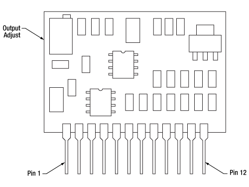
LD1100 Pin Configurations
| Pin | Signal | Description |
|---|---|---|
| 1 | +V | Circuit Power, 8 to 12 VDC, 9 mA + Laser Drive Current NOTE: Internally tied to Laser Diode Anode, the laser anode must be isolated from the power supply COM |
| 2 | COM | Circuit Ground |
| 3 | VREF | Internal 2.5 V reference |
| 4 | PDA | Photodiode Anode |
| 5 | LDA | Laser Diode Anode (Internally Tied to +V (Pin 1)) |
| 6 | LDC | Laser Diode Cathode |
| 7 | RA | When Tied to Common, Puts 100 kΩ in Parallel with 249 kΩ Internal Gain Resistor |
| 8 | RB | When Tied to Common, Puts 33.2 kΩ in Parallel with 249 kΩ Internal Gain Resistor |
| 9 | RC | When Tied to Common, Puts 10 kΩ in Parallel with 249 kΩ Internal Gain Resistor |
| 10 | RD | When Tied to Common, Puts 3.32 kΩ in parallel with 249 kΩ Internal Gain Resistor |
| 11 | RE | When Tied to Common, Puts 1 kΩ in Parallel with 249 kΩ Internal Gain Resistor |
| 12 | ILD | Laser Diode Current Monitor (10 mV/mA) |
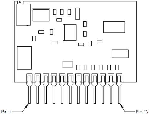
LD1101 Pin Configurations
| Pin | Signal | Description |
|---|---|---|
| 1 | +V | Circuit Power, 8 to 12 VDC, 9 mA + Laser Drive Current NOTE: Internally tied to Laser Diode Anode. The laser anode must be isolated from the power supply COM. |
| 2 | COM | Circuit Ground |
| 3 | VREF | Internal 2.5 V reference |
| 4 | PDC | Photodiode Cathode |
| 5 | LDA | Laser Diode Anode (Internally Tied to +V (Pin 1)) |
| 6 | LDC | Laser Diode Cathode |
| 7 | RA | When Tied to Pin 6, Puts 5 kΩ in parallel with 12.4 kΩ Internal Gain Resistor |
| 8 | RB | When Tied to Pin 6, Puts 1.5 kΩ in parallel with 12.4 kΩ Internal Gain Resistor |
| 9 | RC | When Tied to Pin 6, Puts 499 Ω in parallel with 12.4 kΩ Internal Gain Resistor |
| 10 | RD | When Tied to Pin 6, Puts 160 Ω in parallel with 12.4 kΩ Internal Gain Resistor |
| 11 | RE | When Tied to Pin 6, Puts 33 Ω in parallel with 12.4 kΩ Internal Gain Resistor |
| 12 | ILD | Laser Diode Current Monitor (10 mV/mA) |
EK1101
Laser Anode - Photodiode Cathode Common

| Laser Pin | J1 Pin (on Evaluation Board) | Wire Color |
|---|---|---|
| PDA | PD_A | Green |
| LDA/PDC | LD_A | Red |
| LDC | LD_C | Yellow |
EK1102
Laser Cathode - Photodiode Cathode Common
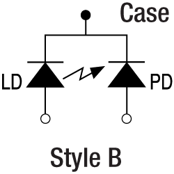
| Laser Pin | J1 Pin (on Evaluation Board) | Wire Color |
|---|---|---|
| PDA | PD_A | Green |
| LDA | LD_A | Yellow |
| LDC/PDC | LD_C | Red |
EK110x Laser Socket Wire Harness

SMART PACK
Click to Enlarge
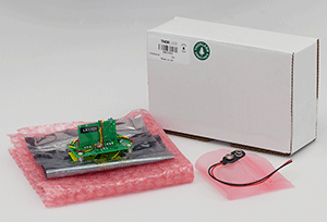
EK1101 Packaging

Smart Pack
- Reduce Weight of Packaging
- Increase Usage of Recyclable Materials
- Improve Packing Integrity
- Decrease Shipping Costs
Thorlabs' Smart Pack Initiative is aimed at minimizing waste while providing adequate protection for our products. By eliminating any unnecessary packaging, implementing design changes, and utilizing eco-friendly materials, this initiative seeks to reduce the environmental impact of our product packaging.
The updated EK1101 and EK1102 packaging primarily consists of recycled paper and cardboard and weighs 19.70% less than the original packaging. This weight change results in a 3.79 kg reduction in travel-based CO2 emissions per year, based on typical product sales.
As we move through our product line, we will indicate re-engineered, eco-friendly packaging with our Smart Pack logo, which can be seen above.
SELECTION GUIDE
Laser Diode Controller Selection Guide
The tables below are designed to give a quick overview of the key specifications for our laser diode controllers and dual diode/temperature controllers. For more details and specifications, or to order a specific item, click on the appropriate item number below.
| Current Controllers | ||||||
|---|---|---|---|---|---|---|
| Item # | Drive Current | Compliance Voltage | Constant Current | Constant Power | Modulation | Package |
| LDC200CV | 20 mA | 6 V | External | Benchtop | ||
| VLDC002 | 25 mA | 5 V | - | Int/Ext | OEM | |
| LDC201CU | 100 mA | 5 V | External | Benchtop | ||
| LD2000R | 100 mA | 3.5 V | - | External | OEM | |
| EK2000 | 100 mA | 3.5 V | - | External | OEM | |
| LDC202C | 200 mA | 10 V | External | Benchtop | ||
| KLD101 | 230 mA | ≤10 V | External | K-Cube™ | ||
| IP250-BV | 250 mA | 8 Va | External | OEM | ||
| LD1100 | 250 mA | 6.5 Va | - | -- | OEM | |
| LD1101 | 250 mA | 6.5 Va | - | -- | OEM | |
| EK1101 | 250 mA | 6.5 Va | - | -- | OEM | |
| EK1102 | 250 mA | 6.5 Va | - | -- | OEM | |
| LD1255R | 250 mA | 3.3 V | - | External | OEM | |
| LDC205C | 500 mA | 10 V | External | Benchtop | ||
| IP500 | 500 mA | 3 V | External | OEM | ||
| LDC210C | 1 A | 10 V | External | Benchtop | ||
| LDC220C | 2 A | 4 V | External | Benchtop | ||
| LD3000R | 2.5 A | -- | - | External | OEM | |
| LDC240C | 4 A | 5 V | External | Benchtop | ||
| LDC4005 | 5 A | 12 V | Int/Ext | Benchtop | ||
| LDC4020 | 20 A | 11 V | Int/Ext | Benchtop | ||
| Dual Temperature and Current Controllers | |||||||
|---|---|---|---|---|---|---|---|
| Item # | Drive Current | Compliance Voltage | TEC Power (Max) | Constant Current | Constant Power | Modulation | Package |
| VITC002 | 25 mA | 5 V | >2 W | - | Int/Ext | OEM | |
| ITC102 | 200 mA | >4 V | 12 W | Ext | OEM | ||
| ITC110 | 1 A | >4 V | 12 W | Ext | OEM | ||
| ITC4001 | 1 A | 11 V | >96 W | Int/Ext | Benchtop | ||
| CLD1010LPa | 1.0 A | >8 V | >14.1 W | Ext | Benchtop | ||
| CLD1011LPb | 1.0 A | >8 V | >14.1 W | Ext | Benchtop | ||
| CLD1015c | 1.5 A | >4 V | >14.1 W | Ext | Benchtop | ||
| ITC4002QCLd | 2 A | 17 V | >225 W | Int/Ext | Benchtop | ||
| ITC133 | 3 A | >4 V | 18 W | Ext | OEM | ||
| ITC4005 | 5 A | 12 V | >225 W | Int/Ext | Benchtop | ||
| ITC4005QCLd | 5 A | 20 V | >225 W | Int/Ext | Benchtop | ||
| ITC4020 | 20 A | 11 V | >225 W | Int/Ext | Benchtop | ||
We also offer a variety of OEM and rack-mounted laser diode current & temperature controllers (OEM Modules, PRO8 Current Control Rack Modules, and PRO8 Current and Temperature Control Rack Modules).
Part Number | Description | Price | Availability |
|---|---|---|---|
EK1101 | Laser Diode Driver Kit Pre-Wired to Pin Style A | $165.12 | Today |
EK1102 | Laser Diode Driver Kit Pre-Wired to Pin Style B | $165.12 | Today |
LD1100 | Constant Power LD Driver for A, B, D, and F Pin Styles, 250 mA Max | $108.41 | Today |
LD1101 | Constant Power LD Driver for C, D, and F Pin Styles, 250 mA Max | $106.31 | Today |
LDS9 | 9 VDC Regulated Power Supply, 2.5 mm Phono Plug, 120 VAC | $100.09 | Lead Time |
