Inspection Tools

- Fiber Scope with 200X Magnification
- 6X and 10X Eye Loupes
- Head Magnifier and Inspection Mirror
- Scratch-Dig Panels for ISO and MIL Standards
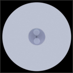
MOTP-ISO
Scratch-Dig Panel
FS200-LC
LC Adapter for
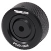
FS201 Scope
FS201
Fiber Inspection Scope
EYL10X
10X Eye Loupe
10125HG
SMA Height Gauge
MAG200K
Magnifier
FS201
Fiber Inspection Scope
OVERVIEW
| Quick Links |
|---|
| Fiber Inspection Scope |
| Connector Adapters |
| SMA Height Gauge |
| Eye Loupes |
| Head-Worn Magnifier |
| Scratch-Dig Panels |
| Inspection Mirror |
Features
- Fiber Inspection Scope to Examine Fiber Polish Quality
- SMA Height Gauge for Connector Coupling Applications
- Eye Loupes Provide 6X or 10X Magnification
- Head-Worn Magnifier Provides Hands-Free 2X Magnification
- Uncertified Scratch-Dig Paddle for Optic Surface Inspection
- Certified Scratch-Dig Panels for Optic Surface Inspection
- Inspection Mirror with Telescoping Handle
The tools on this page are primarily used for inspecting fiber optic ends and other optics. A fiber inspection scope is used to examine the polished end of a terminated fiber. The scope illuminates and magnifies the fiber tip so scratches and other defects can be seen. An SMA connector height gauge provides a way to accurately measure the length of an SMA905 connector, which is important in SMA to SMA coupling. Our premium eye loupes with 6X or 10X magnification are ideal for use in quality control departments. We also offer a head-worn magnifier, an inspection mirror, an uncertified scratch-dig paddle, and certified scratch-dig panels for optic surface inspection.
Fiber Inspection Scope
| FS201 Specifications | |
|---|---|
| Optical Magnification | 200X |
| Field of View | ~Ø600 µm |
| Illumination | Coaxial and Oblique White LEDs (100 000 Hour Lifetime) |
| Optical Filter | Built-In IR Filter |
| Power | 3 LR44 Button Batteries (Included) |
| Included Adapters |
FS201-FC FS201-SMA |
- Critically Examine Fiber Polish Quality
- Scope Includes Two Fiber Adapters:
- FS201-FC: FC/PC, FC/APC, ST®*/PC, and SC/PC Connectors
- FS201-SMA: SMA905 and SMA906 Connectors
- Additional Connector Adapters Sold Separately Below
- Batteries are Included
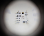
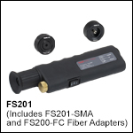
The FS201 Fiber Inspection Scope produces a high-quality, low-distortion image of both the fiber end and surrounding ferrule. With a high-intensity illumination system and 200X magnification, this microscope is powerful enough to offer a clear image of the fiber core as well as the surrounding cladding. The FS201 offers both coaxial and oblique illumination settings. The coaxial setting provides symmetric lighting for high-detail inspection, and the oblique setting provides light at an off-center angle to the fiber end face for higher contrast. The FS201 should not be used to inspect a fiber connected to an active light source; light sources must be disconnected or turned off prior to inspection.
The FS201 includes the FS201-FC adapter for FC-/ST-/SC-terminated fibers (Ø2.5 mm ferrules) and the FS201-SMA adapter for SMA905- and SMA906-terminated fibers (Ø3 mm ferrules). The FS200-LC adapter for LC-terminated fibers (Ø1.25 mm ferrules) and the FS201-PM for polarization-maintaining fibers are available separately below.
The FS201 features two illumination modes, as well as adjustable adapters for fiber alignment.
Fiber Scope Operation
Insert the fiber connector into the adapter until it stops and then firmly hold in place during inspection. To activate illumination, flip the switch on the bottom of the scope; "|" activates coaxial illumination, while "||" activates oblique illumination. Once finished, flip the switch back to "O" to turn the scope off.
To inspect the full surface area of fibers with larger cores or fibers with angled faces, it may be necessary to rotate the fiber connector. This is also useful for differentiating between contaminants on the face of the fiber connector and those on the scope optic itself. In order to see the entire field of view, the rubber eyepiece should be as close as possible to the operator's eye. Operators who normally wear eyeglasses should remove them to fully inspect the fiber. Please note that under normal operation, the focus adjustment knob should not be rotated to its limits. Doing so repeatedly may cause the unit to fail over time.
The FS201 should not be used to view an active emitting fiber. An attenuating laser safety filter in the FS201 reduces the risk of accidental viewing of active fiber emissions. However, due to the IR wavelengths commonly used in fiber optics, the natural aversion reflex to viewing bright light is suppressed and can result in a longer accidental exposure time. Therefore, Thorlabs recommends that light sources must be disconnected from the patch cable or turned off prior to inspection.
Adapter Alignment
Although each adapter comes pre-aligned for use with the FS201, it may be necessary to align the adapter to center the fiber in the field of view for fibers with poor centration. First, follow the basic steps above to inspect a test fiber. Using a 1.5 mm hex key or balldriver, loosen the three setscrews around the edge of the connector adapter at the end of the scope. Look through the illuminated scope, focus on the fiber ferrule, and align the connector until the ferrule face is centered within the field of view. Progressively adjust the three setscrews until the end face is in the center of the scope view.
*ST® is a registered trademark of Lucent Technologies, Inc.
Part Number | Description | Price | Availability |
|---|---|---|---|
FS201 | Fiber Inspection Scope with FS201-FC and FS201-SMA Adapters | $245.26 | 3-5 Days |
Connector Adapters for Fiber Inspection Scope
- Connector Adapters Compatible with the FS201 Fiber Inspection Scope
- Options Available for FC, ST®*, SC, SMA905, SMA906, or LC Connector Types
- FS201-PM Adapter Features V-Groove Aligned to Wide Key Slot (2.2 mm) of the FC/PC Bulkhead
These connector adapters are used with the FS201 Fiber Inspection Scope sold above to enable compatibility with different ferrule and connector types (see table to the right for options). The FS201-PM adapter is like the FS201-FC adapter, except it features a V-groove that is aligned with the wide key slot on the FC/PC bulkhead. This provides a rough guide for determining the relative alignment of the connector key to the fiber stress members when used with polarization-maintaining patch cables.
Although each adapter comes pre-aligned for use with the FS201, it may be necessary to align the adapter to center the fiber in the field of view for fibers with poor centration. First, follow the basic steps above to inspect a test fiber. Using a 1.5 mm hex key or balldriver, loosen the three setscrews around the edge of the connector adapter at the end of the scope. Look through the illuminated scope, focus on the fiber ferrule, and align the connector until the ferrule face is centered within the field of view. Progressively adjust the three setscrews until the end face is in the center of the scope view.
*ST® is a registered trademark of Lucent Technologies, Inc.
Part Number | Description | Price | Availability |
|---|---|---|---|
FS201-FC | FC-Type Connector Adapter for FS201 Fiber Inspection Scope | $50.88 | 3-5 Days |
FS201-PM | Customer Inspired! FC-Type Connector Adapter with Key Alignment Groove for FS201 Fiber Inspection Scope | $50.88 | 3-5 Days |
FS201-SMA | SMA-Type Connector Adapter for FS201 Fiber Inspection Scope | $50.88 | 3-5 Days |
FS200-LC | Customer Inspired! LC-Type Connector Adapter for FS201 Fiber Inspection Scope | $50.88 | 3-5 Days |
SMA Height Gauge
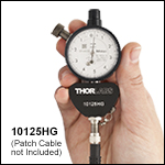
- Measures SMA905 Ferrule Height Relative to 0.3860"
- Calibration Pin Included
- Detailed Calibration and Usage Instructions in Manual
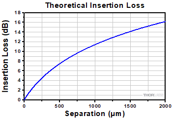
The 10125HG SMA height gauge is ideal for accurately measuring the height of a polished fiber optic SMA905 connector. SMA-to-SMA couplers are designed to have a non-contact interface, and since the insertion loss (IL) of an SMA-SMA junction is dependent on the distance between the two SMA connector end faces, the height of the polished SMA connector is important. We recommend frequent calibration using the attached calibration pin. For detailed calibration instructions, please see the manual. Please note that this gauge is not compatible with SMA906 connectors.
To use, thread an SMA905-terminated fiber into the port at the bottom of the gauge and hand tighten. The connector height measurement on the gauge face is with respect to 0.3860". The photo above shows a ferrule with a height of 0.3863" which reads as +3 ticks on the gauge face. Be sure the gauge is properly calibrated prior to use.
Please note the IEC standard for SMA ferrule height is 0.3850" to 0.3863" (IEC61754-22).
The graph to the right shows the theoretical insertion loss as a function of the separation of two SMA connectors using our M38L01 patch cable. The fiber in this cable has a core diameter of 200 µm, a numerical aperture of 0.39, and an index of 1.4571 at 633 nm. This graph was generated using the following equation:

where z is the separation distance, a is the radius of the core size in µm, NA is the numerical aperture of the fiber, and n0 is the index of the core. Click here to download an interactive Excel file which can be used to calculate and graph the theoretical insertion loss for any fiber.
The height gauge should not be used for testing high-power fiber patch cables as the contact between the gauge and connector end can damage the exposed fiber tip.
Part Number | Description | Price | Availability |
|---|---|---|---|
10125HG | Fiber Optic SMA905 Connector Height Gauge | $460.92 | 3-5 Days |
Premium Eye Loupes: 6X and 10X Magnification
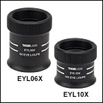
| Specifications | ||
|---|---|---|
| Item # | EYL06X | EYL10X |
| Magnification | 6X | 10X |
| Working Distancea | 30 mm (1.2") | 20 mm (0.8") |
| Field of View | 35 mm (1.4") | 27 mm (1.1") |
| Clear Aperture | Ø27.9 mm (Ø1.10") | |
| Surface Quality | 40-20 Scratch-Dig | |
| Lens Materials | N-BAF10/N-SF6HT | |
| Broadband AR Coating | ||
| Wavelength Range | ||
| Average Reflectance | <0.5% | |
- Magnification: 6X or 10X
- Uses a Pair of Glass Achromatic Doublets
- AR Coating on All Glass-to-Air Optical Surfaces
- Large Field of View: Ø1.4" for 6X and Ø1.1" for 10X
- Small Form Factor
Thorlabs' Premium Eye Loupes provide clear magnification that is ideal for inspecting optics and small parts. The eye loupes were designed by Thorlabs to maximize working distance when used with the knurled edge oriented towards the eye. They use a pair of glass achromatic doublets to minimize chromatic and other aberrations. The AR coating on each optical surface is optimized to reduce internal reflections at wavelengths visible to the human eye. These high-quality magnifiers are suitable for quality control applications in industry or inspecting optics in the lab. They are available in 6X and 10X magnifications.
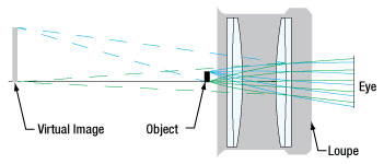
Click to Enlarge
This ray tracing demonstrates the virtual image seen through the EYL06X eye loupe.
Eye Loupe Magnification
The magnification specification provided for these eye loupes is determined using the standard magnification definition:
where M is the magnification, Himage is the image height, and Hobject is the object height. This definition is valid when used at the specified working distance. When using this equation, the magnification of EYL06X and EYL10X is 6.0 and 10.0, respectively, as specified in the table above.
The maximum magnification that can be achieved on the human retina is given by the loupe magnification definition, which is a thin-lens formula:
where M is the magnification and f is the focal length of the lens in mm. When using this equation, the magnification of EYL06X is 5.5 and the magnification of EYL10X is 8.9.
Part Number | Description | Price | Availability |
|---|---|---|---|
EYL06X | Premium 6X Eye Loupe | $181.75 | 3-5 Days |
EYL10X | Premium 10X Eye Loupe | $181.75 | 3-5 Days |
Standard 10X Eye Loupe
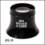
- 10X Magnification
- Hastings Design
- Lightweight
This Bausch + Lomb® loupe is an ideal, economical tool for inspecting optics and small parts. The eyepiece provides a clear, 10X magnification. This loupe is designed to be used with the flared edge facing the eye. If the JEL10 does not meet your inspection needs, our premium eye loupes (featured above) provide a higher image quality and a wider field of view suitable for industry inspection applications.
Part Number | Description | Price | Availability |
|---|---|---|---|
JEL10 | Standard 10X Eye Loupe | $28.27 | 3-5 Days |
Head-Worn Magnifier
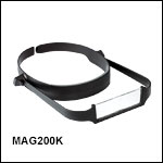
- 2.0X Magnification
- Can be Worn With or Without Eyeglasses
- ESD Compliant
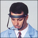
This head-worn inspection magnifier is ESD compliant and cleanroom compatible. It is ideal for inspecting components when high magnification is not required and may be worn with or without prescription eyeglasses. The position of the magnifying lenses is adjustable so that they can be swung out of your line of sight when magnification is not needed.
Part Number | Description | Price | Availability |
|---|---|---|---|
MAG200K | MagEyes Inspection Magnifier, 2.0X Magnification | $37.72 | Lead Time |
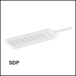
Optic Surface Imperfection (Scratch-Dig) Paddle
| Measured Feature Dimensions of SDP Mold | |||
|---|---|---|---|
| Dig Number | Mean Dig Diameter | Dig Diameter Tolerance | Dig Separation Distance |
| 100 | 1.00 mm (0.040") | - | 20.00 mm (0.787") |
| 70 | 0.70 mm (0.028") | ||
| 50 | 0.50 mm (0.020") | ||
| 40 | 0.40 mm (0.016") | ±0.01016 mm (0.0004") | |
| 20 | 0.20 mm (0.008") | ±0.00762 mm (0.0003") | |
| 10 | 0.10 mm (0.004") | ±0.00508 mm (0.0002") | 1.00 mm (0.040") |
| 5 | 0.05 mm (0.002") | ±0.00338 mm (0.0001") | 1.00 mm (0.040") |
- Acrylic Molded Visual Scratch-Dig Reference for Optical Element Inspection
- Seven Different Sizes of Both Scratches and Digs
- Scratch-Dig Defined According to MIL-PRF-13830B
Scratch-dig paddles are used to determine the cosmetic surface quality of an optic. Made of acrylic and cast from a mold, Thorlabs' SDP Scratch-Dig Paddle contains 7 rectangular sections and 7 circular sections each of which contains a different scratch or a different dig. Scratch-dig refers to the cosmetic quality of the surface of an optic and is defined by the U.S. military (MIL-PRF-13830B). A scratch is defined as any marking or tearing of the glass surface and the digs are small rough spots on the glass surface, similar to pits in appearance. This reference contains scratch numbers 10, 20, 40, 60, 80, 120, and 160, and dig numbers 5, 10, 20, 40, 50, 70, and 100; the scratches are classified topographically and comply with MIL-PRF-13830B standards, while the mean diameter of each of the digs is physically measured. A table showing measured feature dimensions for the digs in the molds used to create these paddles is shown to the right.
Although not certified, this paddle contains scratch and dig features that can be used as a reference to compare with any optic for classification. To use the paddle, place it next to the optic you are inspecting and compare the imperfections on the optic's surface to the imperfections on the paddle. We also offer Scratch-Dig Panels (sold below) that are fabricated photolithographically and conform to the ISO 10110-7 and ANSI/OEOSC OP1.002 standards.
Procedure:
The surface quality is to be specified by a number such as 60-40 scratch-dig. The first number corresponds to the max scratch width compared to the reference scratches on the SDP paddle. It does not correspond directly to a precise scratch width. The next number indicates the mean diameter of a dig in hundredths of a millimeter. The table to the right can be used to quickly convert the dig number into millimeters or inches.
Part Number | Description | Price | Availability |
|---|---|---|---|
SDP | NEW! Scratch-Dig Paddle | $150.00 | 3-5 Days |
Optic Surface Imperfection (Scratch-Dig) Panels
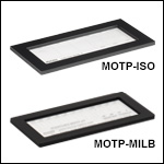
- Visual Scratch-Dig References for Optical Element Inspection
- Two Quality Standards Available:
- MOTP-ISO: ISO 10110-7
- MOTP-MILB: MIL-PRF-13830B for Digs Numbered 5 to 50 and ANSI/OEOSC OP1.002 for All Digs and Scratches
- Borosilicate Substrate with Plastic Frame; Hard Foam Case Included
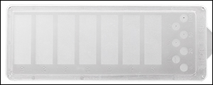
These Scratch-Dig Panels are a certified traceable option used to determine the cosmetic surface quality of an optic. We offer two scratch-dig panels, each with their own set of imperfections. For details and dimensions on the photolithographically marked patterns, please refer to the photo to the right and the expandable table below.
The MOTP-ISO panel is defined by the ISO 10110-7 standard. The imperfections are evaluated and classified depending on their physical sizes with no distinction between a scratch and a dig. All imperfections can be considered scratches of different sizes.
The MOTP-MILB panel is defined by the ANSI/OEOSC OP1.002 standard for scratches and digs and also corresponds to the MIL-PRF-13830B standard for digs labeled 5 to 50. This panel places an emphasis on the shape of the imperfection and is divided in two parts, scratches and digs. The given grade numbers for the imperfections indicate scratch width in µm or dig diameter in 1/100 mm.
To use these panels, place them next to the optic under inspection and compare the imperfections on the optic's surface to the imperfections on the panel. Both of our panels are designed for use with dimensional analysis, which facilitates an unbiased qualification of the optic’s imperfections. Manufacturers and users are recommended to use the same standard.
Certificates with nominal and measured feature dimensions for the masks used to create these panels are available by clicking on the Support Docs icons (![]() ) below.
) below.
| MOTP-ISO Panel Pattern Dimensions [ISO 10110-7] |
|---|
| MOTP-MILB Panel Pattern Dimensions [ANSI/OEOSC OPI1.002 (Digs and Scratches) and MIL-PRF-13830B (Digs 5 to 50)] |
|---|
Part Number | Description | Price | Availability |
|---|---|---|---|
MOTP-ISO | Customer Inspired! Scratch-Dig Panel, ISO 10110-7 Standard | $515.96 | 3-5 Days |
MOTP-MILB | Scratch-Dig Panel, MIL-PRF-13830B and ANSI/OEOSC OP1.002 Standards | $515.96 | 3-5 Days |
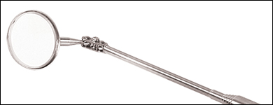
Inspection Mirror
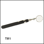
Click to Enlarge
Partial Extension of Telescoping Arm
- Corrosion-Resistant Stainless Steel Telescoping Handle
- High-Quality, Low Distortion Ø1.25" Glass Mirror
- Articulated Joint Adds Versatility in Mirror Positioning
- 8.50" (21.6 cm) Solid Length, 35" (88.9 cm) Extended Length
This telescoping inspection mirror is ideal for viewing components in hard-to-reach areas of the lab.
Part Number | Description | Price | Availability |
|---|---|---|---|
TM1 | Telescoping Inspection Mirror | $28.63 | 3-5 Days |

