Photomultiplier Modules (PMTs)

- Several Models Cover 185 - 920 nm Wavelength Range
- Alkali and GaAsP Photocathodes Available
- SM1 or C-Mount Threads for Filters or Lens Tubes
- Models Designed for Single- and Multi-Channel
Detection
PMM02
300 - 800 nm
Multialkali, Standalone
PMT2101
300 - 720 nm
GaAsP, Standalone
PMTSS2
185 - 900 nm
Multialkali, Two Channels
OVERVIEW
Click to Enlarge
Click for Logarithmic Plot
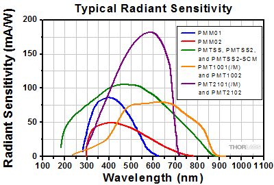
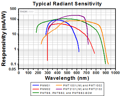
This graph shows typical radiant sensitivity curves for our PMT modules. The PMT2101(/M) and PMT2102 provide the highest radiant sensitivity, but are also the most susceptible to degradation from high intensity illumination. The PMM01, PMM02, PMT1001(/M), PMT1002, PMT2101(/M) and PMT2102 feature built-in transimpedance amplifiers for simpler integration with setups. The PMM01, PMM02, PMT1001(/M), and PMT2101(/M) also offer internal SM1 threads and four 4-40 taps for direct compatibility with our SM1 lens tubes and 30 mm cage system.
Features
- Bialkali, Multialkali, and GaAsP Detectors for Wavelengths from 185 nm to 920 nm
- Typical Radiant Sensitivities from 51 mA/W to >176 mA/W (See Graph to the Right)
- Various Mounting Features (See Selection Guide Tab)
- Some Models Offer Built-In Transimpedance Amplifiers
- PMTSS2 Modules are Designed for Building Expandable Multi-Channel Imaging Setups
- Control Software for 64-Bit Windows® 7 or 10 (See Software Tab)
Photomultiplier tubes (PMTs) are used to detect faint optical signals from weakly emitting sources. Compared to avalanche photodetectors (APDs), they offer significantly larger active areas, making them ideal for capturing signals that may be diverging due to scatter or nonlinear optical effects. These PMTs are controlled with an included software package designed for use with 64-Bit Windows® 7 or 10, which provides a GUI for adjusting gain, output offset voltage, and bandwidth. This software package includes .NET, C++, and LabVIEW drivers.
Thorlabs offers PMTs utilizing alkali or GaAsP detector elements, which offer sensitivity in the UV, visible, and NIR. Their performance can be quantified by their quantum efficiency (in %), which describes how many incident photons are converted to photoelectrons. The quantum efficiency is closely related to the radiant sensitivity (in mA/W), as shown in the equation in footnote b below. Radiant sensitivity curves for Thorlabs' PMTs are given in the graph to the right.
In order to generate high internal gain, the electrons initially generated at the PMT's photocathode are accelerated by a high-voltage potential, on the order of kV. This potential causes the electrons to strike several dynodes that generate secondary electrons. The photocurrent that has accumulated after the final dynode stage represents the amplified signal and is collected by an anode. (See the PMT Tutorial tab for more details.) All of our PMT modules feature built-in high-voltage circuitry that eliminates the need for a standalone high-voltage source, reducing the package's footprint and risk of electric shock.
The photocurrent collected at the anode is typically sent into a transimpedance amplifier that converts the current into a voltage and provides additional amplification. Our PMM01, PMM02, PMT1001(/M), PMT1002, PMT2101(/M), and PMT2102 modules include a built-in transimpedance amplifier, allowing them to be connected directly to lab equipment that requires voltage signals. In contrast, the PMTSS, PMTSS2, and PMTSS2-SCM have no built-in amplifier. They are compatible with our TIA60 Transimpedance Amplifier, as well as other transimpedance amplifiers, which are available separately.
| PMT Comparisona | Standalone | Multi-Channel | ||||
|---|---|---|---|---|---|---|
| Item # | PMM01 | PMM02 | PMTSS | PMT1001(/M) PMT1002 |
PMT2101(/M) PMT2102 |
PMTSS2 PMTSS2-SCM |
| Photocathode Material | Bialkali | Multialkali | Multialkali | Multialkali | GaAsP | Multialkali |
| Wavelength Range | 280 - 630 nm | 300 - 800 nm | 185 - 900 nm | 230 - 920 nm | 300 - 720 nm | 185 - 900 nm |
| Radiant Sensitivityb (Typ.) |
80 mA/W (at 400 nm) | 51 mA/W (at 420 nm) | 105 mA/W (at 450 nm) | 78 mA/W (at 630 nm) | 176 mA/W (at 550 nm) | 105 mA/W (at 450 nm) |
| Photocathode Active Area |
Ø22 mm | Ø21 mm | 3.7 mm x 13.0 mm (H x V) |
Ø8 mm | Ø5 mm | 3.7 mm x 13.0 mm (H x V) |
| Transimpedance Amplifier |  |
 |
Not Included (Compatible with TIA60) |
 |
 |
Not Included (Compatible with TIA60) |
SPECS
Standalone Alkali PMTs
| Item # | PMM01 | PMM02 | PMTSS | PMT1001(/M) | PMT1002 |
|---|---|---|---|---|---|
| Detector Specifications | |||||
| Wavelength Range | 280 - 630 nm | 300 - 800 nm | 185 - 900 nm | 230 - 920 nm | |
| Peak Wavelength (λp) | 400 nm | 420 nm | 450 nm | 630 nm | |
| Radiant Sensitivity at λpa (Typ.) |
80 mA/W | 51 mA/W | 105 mA/W | 78 mA/W | |
| Quantum Efficiency at λpa (Calculated from Radiant Sensitivity) |
25% | 15% | >28% | >15% | |
| PMT Gain (Max) | 7.1 x 10⁶ | 5.1 x 10⁵ | >1.0 x 10⁷ See Graphs Tab for PMT Gain vs. Control Voltage |
>3.0 × 10⁶ See Graphs Tab for PMT Gain vs. Control Voltage |
|
| HV Control Voltage (Max) | 0 V to +1.8 Vb | 0 V to +1.25 Vb | +0.25 V to +1.00 V (Recommended) +0.25 V to +1.20 V (Maxc) |
+0.50 V to +1.10 V Software Controlled |
|
| Control Voltage Connector | 2.5 mm Mono Jack | M8 x 1 Power Connector | USB Mini | ||
| PMT Voltage | 0 V to -1800 Vb,d | 0 V to -1250 Vb,d | +250 V to +1000 V (Recommended) +250 V to +1200 V (Maxc) |
+500 V to +1100 V | |
| Photocathode Active Area | Ø22 mm | Ø21 mm | 3.7 mm x 13.0 mm (H x V) | Ø8 mm | |
| Dark Currente | 0.3 - 3 nA (at 20 °C) | 3 nA (Typ.) 20 nA (Max) (After 30-Minute Storage in Darkness) |
2 nA (Typ.) 10 nA (Max) |
10 nA (Typ.) 100 nA (Max) |
|
| Dark Count Ratee |
100 s-1 (at 20 °C) | - | - | - | |
| Warm-Up Time Before Applying Control Voltagee | <10 s | 30 to 60 Minutes | 30 to 60 Minutes | ||
| Anode Currentf | 100 µA (Max)g | 10 µAh | 100 µAh | ||
| Rise and Fall Time | 15 µs | 1.4 ns | 0.57 ns (Rise)i | ||
| Photocathode Type | Bialkali | Multialkali | Multialkali | Multialkali | |
| Photocathode Geometry | Head On | Side On | Head On | ||
| Window | Borosilicate, Plano-Concave (n = 1.49) |
UV-Transmitting Glass (n = 1.48) |
Borosilicate, Flat Window (n = 1.487) |
||
| Transimpedance Amplifier Specifications | |||||
| Transimpedance Gain | High Z: 1 x 10⁶ V/A 50 Ω: 5 x 10⁵ V/A |
No Amplifier Included | 11000 +1000 / -500 V/A | ||
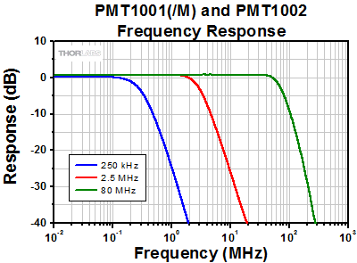
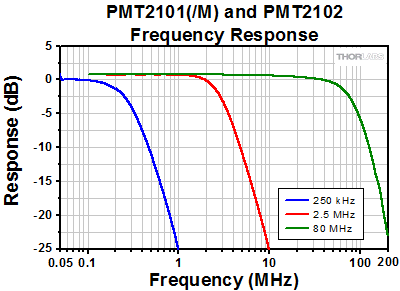
| Amplifier Bandwidth (at 6 dB)j | DC to 20 kHz | N/A | Software Configurable DC to 80 MHz, 2.5 MHz, or 250 kHz |
||
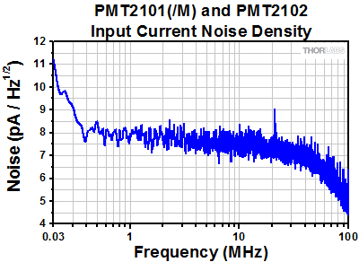
| Amplifier Noise (Typ.) | 2 mV (RMS) | N/A | 5.8 pA / √Hz (Total Input Noise at DC to 80 MHz Bandwidth) 6.5 pA / √Hz (Input Current Noise at 1 MHz, Cin = 4 pF) |
||
| Amplifier Offset (Typ.) | 1 mV | N/A | ±103 µV / °Ck | ||
| Output Signall | |||||
| Output Voltage | 0 - 10 V (High Z) 0 - 5 V (50 Ω) |
N/A | ±1.5 V (50 Ω) | ||
| Output Current | N/A | 10 µA (Max) | N/A | ||
| Connector | SMA | BNC | SMA | ||
| Physical Specifications | |||||
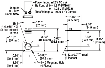
| Module Dimensions | 3.65" x 1.60" x 2.46" (92.8 mm x 40.6 mm x 62.5 mm) |
5.20" x 1.26" x 2.50" (132.0 x 32.1 x 63.5 mm) |
3.43” x 1.60” x 2.10” (87.2 mm x 40.6 mm x 53.5 mm) |
3.32" x 1.35" x 1.95" (84.4 mm x 34.3 mm x 49.6 mm) |
|
| Power Input |
+12 V Pin: 40 mA Max, +12 V to +15 V -12 V Pin: 10 mA Max, -12 V to -15 V |
15 VDC, 7 mA Max | 5 VDC +4.5 V to +5.5 V 350 mA Typ., 500 mA Max |
||
| Included Power Supply | ±12 VDC (100/120/230 VAC, 50 or 60 Hz, Switchable)m |
- | - | ||
| Operating Temperature | 5 to 55 °C | 15 to 40 °C | 5 to 50 °C | ||
| Storage Temperature | -40 to 55 °C | -20 to 50 °C | -20 to 50 °C | ||
| Module Weight |
200 g (0.44 lbs) | 200 g (0.44 lbs) | 0.3 kg (0.66 lbs) | 300 g (0.66 lbs) | |
| Mounting Options | |||||
| Internal SM1 Threads |  (In Front of Window) (In Front of Window) |
 (In Front of Window) (In Front of Window) |
- |  (In Front of Window) (In Front of Window) |
- |
| Internal C-Mount Threads | - | - |  (In Front of Window) (In Front of Window) |
- |  (In Front of Window) (In Front of Window) |
| Mounting Holes | Three 8-32 Taps (8-32 to M4 Adapter Included) |
Three 8-32 Taps (8-32 to M4 Adapter Included) |
- | 1/4"-20 (M6) Tap | - |
| 30 mm Cage System |  (Four 4-40 Taps) (Four 4-40 Taps) |
 (Four 4-40 Taps) (Four 4-40 Taps) |
- |  (Four 4-40 Taps) (Four 4-40 Taps) |
- |
GaAsP PMTs
| Item # | PMT2101(/M) | PMT2102 |
|---|---|---|
| Detector Specifications | ||
| Wavelength Range | 300 - 720 nm | |
| Peak Wavelength (λp) | 580 nm | |
| Radiant Sensitivitya (Typ.) | 176 mA/W at 550 nm | |
| 108 mA/W at 420 nm | ||
| Quantum Efficiencya (Calculated from Radiant Sensitivity) |
39% at 550 nm (Typical)b | |
| 32% at 420 nm (Typical)b | ||
| PMT Gain (Max) | >1.0 × 10⁶ | |
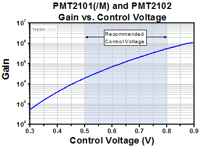
| Control Voltage | +0.50 V to +0.80 V (Recommended) +0.5 V to +1.0 V (Maxc) Software Controlled |
|
| Control Voltage Connector | USB Mini | |
| PMT Voltage | +500 V to +800 V (Recommended) +500 V to +1000 V (Max) |
|
| Photocathode Active Area | Ø5 mm | |
| Dark Count Rated, e |
6000 s-1 (at 25 °C, Typical) 18000 s-1 (at 25 °C, Maximum) |
|
| Warm-Up Time Before Applying Control Voltagee |
30 to 60 minutes (at 25 °C) | |
| Anode Currentf | 500 µA (Max) | |
| Rise Timeg | 1.00 ns | |
| Photocathode Type | GaAsP | |
| Photocathode Geometry | Head On | |
| Window | Borosilicate, Flat Window | |
| Transimpedance Amplifier Specifications | ||
| Transimpedance Gain | 11000 +1000 / -500 V/A | |
| Amplifier Bandwidth (at 6 dB)h,i |
Software Configurable DC to 80 MHz, 2.5 MHz, or 250 kHz |
|
| Amplifier Noisei (Typ.) | 5.8 pA / √Hz (Total Input Noise at DC to 80 MHz Bandwidth) 6.5 pA / √Hz (Input Current Noise at 1 MHz, Cin = 4 pF) |
|
| Amplifier DC Offset Drift (Typ.) | ±103 µV / °C | |
| Maximum Inputj | ±500 μA | |
| Output Signalk | ||
| Output Voltage | ±1.5 V (50 Ω) | |
| Output Current | N/A | |
| Connector | SMA | |
| Physical Specifications | ||
| Module Dimensions | 3.43” × 1.60” × 2.10” (87.2 × 40.6 × 53.5 mm) |
3.32" × 1.35" × 1.95" (84.4 × 34.3 × 49.6 mm |
| Power Input |
5 VDC (+4.5 V to +5.5 V) 350 mA Typ., 500 mA Max |
|
| Operating Temperature | 5 to 35 °C | |
| Storage Temperature | -20 to 50 °C | |
| Module Weight |
300 g (0.66 lb) | |
| Mounting Options | ||
| Internal SM1 Threads |  (In Front of Window) (In Front of Window) |
- |
| Internal C-Mount Threads | - |  (In Front of Window) (In Front of Window) |
| Mounting Holes | 1/4"-20 (M6) Tap | - |
| 30 mm Cage System |  (Four 4-40 Taps) (Four 4-40 Taps) |
- |
Multi-Channel PMTs
| Item # | PMTSS2 | PMTSS2-SCM |
|---|---|---|
| Detector Specifications | ||
| Wavelength Range | 185 - 900 nm | |
| Peak Wavelength (λp) | 450 nm | |
| Radiant Sensitivity at λpa (Typ.) |
105 mA/W | |
| Quantum Efficiency at λpa (Calculated from Radiant Sensitivity) |
>28% | |
| PMT Gain (Max) | >1.0 × 10⁷ See Graphs Tab for PMT Gain vs. Control Voltage |
|
| Control Voltage | +0.25 V to +1.00 V (Recommended) +0.25 V to +1.20 V (Maxb) |
|
| Control Voltage Connector | M8 x 1 Power Connector | |
| PMT Voltage | +250 V to +1000 V (Recommended) +250 V to +1200 V (Maxb) |
|
| Photocathode Active Area | 3.7 mm × 13.0 mm (H × V) | |
| Dark Currentc | 2 nA (Typ.) 10 nA (Max) |
|
| Dark Count Ratec |
- | |
| Warm-Up Time Before Applying Control Voltagec |
30 to 60 Minutes | |
| Anode Currentd | 10 µA (Max) | |
| Rise and Fall Time | 1.4 ns | |
| Photocathode Type | Multialkali | |
| Photocathode Geometry | Side On | |
| Window | UV-Transmitting Glass (n = 1.48) | |
| Transimpedance Amplifier Specifications | ||
| Transimpedance Gain | No Amplifier Included | |
| Amplifier Bandwidth (at 6 dB)e |
N/A | |
| Amplifier Noise (Typ.) | N/A | |
| Amplifier Offset (Typ.) | N/A | |
| Output Signalf | ||
| Output Voltage | N/A | |
| Output Current | 10 µA (Max) | |
| Connector | BNC | |
| Physical Specifications | ||
| Module Dimensions | 10.18" × 8.09" × 3.40" (258.5 × 205.5 × 86.4 mm) |
8.09" × 2.43" × 3.40" (205.5 × 61.8 × 86.4 mm) |
| Power Input |
15 VDC, 7 mA Max | |
| Operating Temperature | 15 to 40 °C | |
| Storage Temperature | -20 to 50 °C | |
| Module Weight |
1.4 kg (3.08 lb) | 0.9 kg (1.98 lb) |
| Mounting Options | ||
| Internal SM1 Threads |  (On Input Port and (On Input Port andFilter Cube) |
 (On Input Port and (On Input Port andFilter Cube) |
| Internal C-Mount Threads |  (In Front of Windowg) (In Front of Windowg) |
 (In Front of Windowg) (In Front of Windowg) |
| Mounting Holes | 1/4" (M6) Counterbored Slots | 1/4" (M6) Counterbored Slots |
| 30 mm Cage System | - | - |
GRAPHS
Alkali PMTs
Click to Enlarge
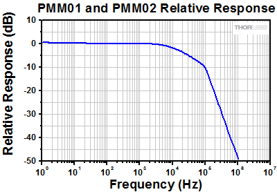
Relative Response of PMM01 and PMM02 Modules
Click to Enlarge
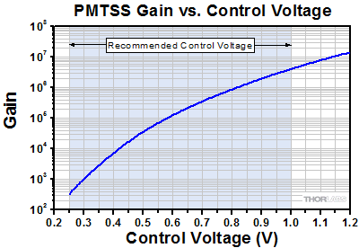
Gain of PMTSS, PMTSS2, and PMTSS2-SCM Modules
Although the PMT may be operated up to a maximum control voltage of +1.20 V, operation beyond the recommended control voltage range may decrease the PMT's operational lifetime.
Click to Enlarge
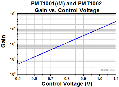
Gain of PMT1001(/M) and PMT1002
GaAsP PMTs
Click to Enlarge
Amplifier Frequency Response of PMT2101(/M) and PMT2102
Click to Enlarge
Gain of PMT2101(/M) and PMT2102
Although the PMT may be operated up to a maximum control voltage of +1.0 V, operation beyond the recommended control voltage range may decrease the PMT's operational lifetime.
Click to Enlarge
Input Current Noise Density of PMT2101(/M) and PMT2102
DRAWINGS
Standalone Alkali PMTs
Click to Enlarge
PMM01 and PMM02 Mechanical Drawing

Click to Enlarge
PMTSS Mechanical Drawing
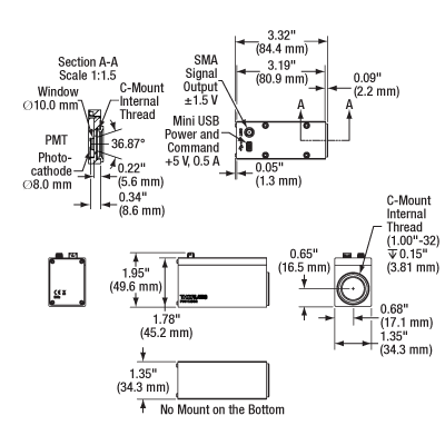
Click to Enlarge
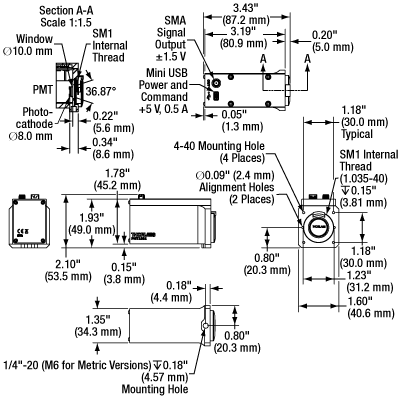
PMT1002 Mechanical Drawing
GaAsP PMTs
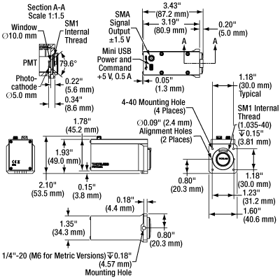
Click to Enlarge
PMT2101(/M) Mechanical Drawing
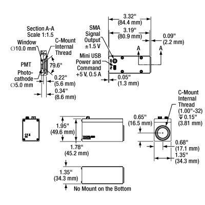
Click to Enlarge
PMT2102 Mechanical Drawing
PMTs for Multi-Channel Detection
PIN DIAGRAMS
PMM01 and PMM02 Modules
These PMT modules ship with a Y-cable for control voltage and power (6-pin Hirose to 2.5 mm mono jack and 3-pin Lumberg power connector). This cable is pictured in the Shipping List tab.
Connectors on PMT Module
Power Connector
6-Pin Hirose
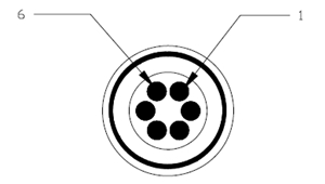
| Pin | Assignment |
|---|---|
| 1 | Power Supply Input (+12 VDC to +15 VDC) |
| 2 | Power Supply Input (-12 VDC to -15 VDC) |
| 3 | 0 V |
| 4 | 0 V |
| 5 | No Connection |
| 6 | Control Voltage (PMM01: 0 V to +1.8 V) (PMM02: 0 V to +1.25 V) |
Output Signal
Female SMA

Output Voltage:
0 - 5 V (50 Ω)
0 - 10 V (High Z)
Connectors on Y-Cable
Power Supply Connection
3-Pin Lumberg RKMC-3
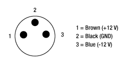
| Pin | Assignment |
|---|---|
| 1 | Power Supply Input (+12 VDC to +15 VDC) |
| 2 | Ground |
| 3 | Power Supply Input (-12 VDC to -15 VDC) |
Control Voltage
2.5 mm Mono Plug

Tip: Ground
Barrel: 0 to +1.25 VDC
PMT1001(/M), PMT1002, PMT2101(/M), and PMT2102 Modules
These PMT modules ship with a SMA to SMB cable and a Mini USB to USB A cable. These cables are pictured in the Shipping List tab.
Power Connector
USB Mini

Input Voltage:
+0.50 V to +1.10 V [PMT1001(/M) and PMT1002]
+0.50 V to +0.80 V
[Recommended Range for PMT2101(/M) and PMT2102]
Output Signal
Female SMA

Output Voltage:
±1.5 V (50 Ω)
PMTSS, PMTSS2, and PMTSS2-SCM Modules
These PMT modules ship with a male M8 x 1 connector with colored wire leads. This connector is pictured in the Shipping List tab.
Power Connector
Female M8 x 1
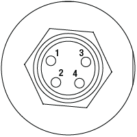
| Pin | Assignment | Wire Colora |
|---|---|---|
| 1 | Power Supply Input (+15 VDC) | Brown |
| 2 | Control Voltage (Recommended: +0.25 V to +1.00 V; Maxb: +0.25 V to +1.20 V) |
White |
| 3 | No Connection | Blue |
| 4 | Power Supply Return (Ground) | Black |
Output Signal
BNC Female
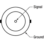
Output Current: 10 µA (Max)
SHIPPING LIST
Click to Enlarge
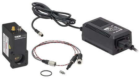
PMM01 and PMM02 Contents
PMM01 and PMM02
Item #'s PMM01 and PMM02 consist of:
- PMT Module
- SM1RR Retaining Ring
- AS4M8E 8-32 to M4 Thread Adapter
- Y-Cable for Control Voltage and Power (6-pin Hirose to 2.5 mm Mono Jack and 3-pin Lumberg
Power Connector) - 2.5 mm Mono Plug
- ±12 V Power Supply with Region Specific Power Cord
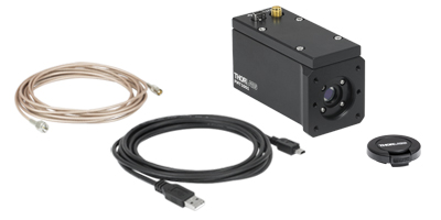
Click to Enlarge
PMT1001(/M) Contents
PMT1001(/M)
Item # PMT1001(/M) consists of:
- PMT Module
- USB 2.0 Cable (A to Mini)
- SMA to SMB Cable
- SM1 End Cap
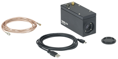
Click to Enlarge
PMT1002 Contents
PMT1002
Item # PMT1002 consists of:
- PMT Module
- USB 2.0 Cable (A to Mini)
- SMA to SMB Cable
- C-Mount Lens Cap (Replacement Item # CMCP2)
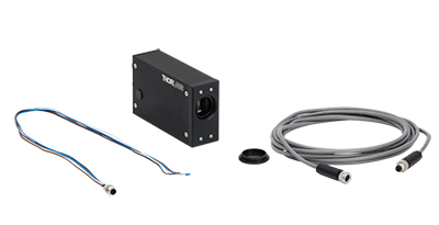
Click to Enlarge
PMTSS Contents
PMTSS
Item # PMTSS consists of:
- PMT Module
- Male M8 x 1 Connector with Colored Wire Leads
- M8 x 1 Extension Cord
- C-Mount Cap (Replacement Item # CMCP2)
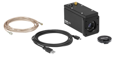
Click to Enlarge
PMT2101(/M) Contents
PMT2101(/M)
Item # PMT2101(/M) consists of:
- PMT Module
- USB 2.0 Cable (A to Mini)
- SMA to SMB Cable
- SM1 End Cap
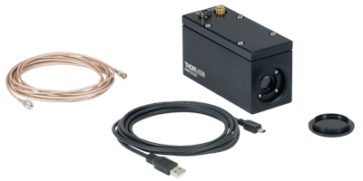
Click to Enlarge
PMT2102 Contents
PMT2102
Item # PMT2102 consists of:
- PMT Module
- USB 2.0 Cable (A to Mini)
- SMA to SMB Cable
- C-Mount Lens Cap (Replacement Item # CMCP2)
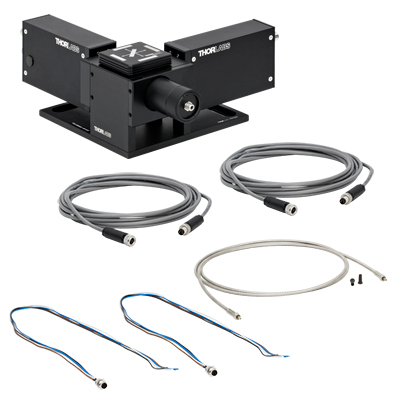
Click to Enlarge
PMTSS2 Contents
PMTSS2
Item # PMTSS2 consists of:
- Two Detachable PMT Modules
- DFM1T1 Filter Cube Top
- Mechanical Housing with SMA905-Terminated Fiber Collimation Assembly and Male Dovetail for
PMTSS2-SCM Add-On Module - Two Male M8 x 1 Connectors with Colored Wire Leads
- Two M8 x 1 Extension Cords
- Ø910 µm Core, 0.22 NA, SMA905-Terminated Fiber Patch Cable for 250 - 1200 nm
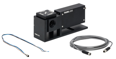
Click to Enlarge
PMTSS2-SCM Contents
PMTSS2-SCM
Item # PMTSS2-SCM consists of:
- Detachable PMT Module
- DFM1T1 Filter Cube Top
- Mechanical Housing with Female Dovetail for the PMTSS2 Module and Male Dovetail for Additional
PMTSS2-SCM Modules - Male M8 x 1 Connector with Colored Wire Leads
- M8 x 1 Extension Cord
SOFTWARE
The PMT1001(/M), PMT1002, PMT2101(/M), and PMT2102 standalone PMTs can be controlled using Thorlabs' software. The software download page below offers a link to the GUI interface as well as a LabVIEW™ software development kit (SDK) to allow these PMTs to be controlled using custom imaging software. The most recent firmware for these PMTs is available as well.
PMT TUTORIAL
Choosing a Photomultiplier Tube for Your Application
Introduction
Since the first commercial photomultiplier tube (PMT) was developed in the early 1940s, it has remained the detector of choice for experiments requiring fast response times and high sensitivity. Today, the PMT is a staple for research in many fields including analytical chemistry, particle physics, medical imaging, industrial process control, astronomy, and atomic and molecular physics. This tutorial provides introductory material for the principle of operation and key specifications to consider when choosing a PMT for a given application.
Basic Principle of Operation
Photomultiplier Tubes (PMTs) are sensitive, high-gain devices that provide a current output that is proportional to the incident light. The PMT consists of a glass vacuum tube that houses a photoemissive material called a photocathode, 8 - 14 secondary emitting electrodes called dynodes, and a collection electrode called an anode. If a photon with sufficiently high energy (i.e. more energy than the binding energy of the photocathode material) is incident on the photocathode, it is absorbed, and an electron is released in accordance with the photoelectric effect. Since the first dynode is maintained at a higher potential than the cathode (thereby creating a potential difference between these two elements), the ejected electron will accelerate toward the dynode and crash into it, releasing secondary electrons. Typically, 3 - 5 secondary electrons are released during this process. Each of these 3 - 5 electrons is then in turn accelerated toward and crashes into the second dynode, thereby releasing 3 - 5 more electrons. This process continues through the entire dynode chain providing an electron gain of 3 - 5. Typically, each dynode is maintained at a potential that is 100 - 200 V higher than the previous one. At the end of the dynode chain, the electrons are collected by the anode and a current pulse is output. However, to read that pulse, the current usually needs to be converted to a voltage; the simplest way to do this is to connect a low load resistance across the anode and ground. Thorlabs' PMM01 and PMM02 modules use a transimpedance amplifier (TIA) to convert the nA- or µA-scale current output by the anode to a voltage in the mV or V range, respectively. In comparison, our PMTSS, PMTSS2, and PMTSS2-SCM modules do not include a TIA.
For example, if a PMT consists of 8 dynodes as shown in the figure below and each electron is able to produce 4 secondary electrons, the total current amplification after traveling through the dynode chain will be 48 ≈ 66,000. Each photoelectron for this example PMT produces a charge avalanche at the anode of Q = 48e. The corresponding voltage pulse is V = Q/C = 48e /C where C is the capacitance of the anode (including connections). If the capacitance is 5 pF, the output voltage pulse will be 2.1 mV.
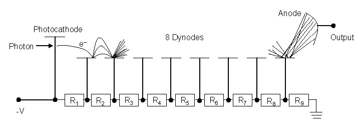
Spectral Response
When choosing a PMT for a given application, the photocathode material should be matched to the intended application. Generally, the long-wavelength cutoff is determined by the photocathode, while the window material determines the short-wavelength cutoff. PMTs are manufactured for wavelengths from the deep UV through the infrared. However, since the photocathode is responsible for converting incident photons into electrons, the efficiency with which it does this for the wavelength of interest is of utmost importance. There are a variety of materials used for photocathodes, each with a different work function and each intended for use in a different spectral range.
Quantum Efficiency (QE) is a specification that is usually expressed as a percentage and is associated with the PMTs ability to convert incident photons into detectable electrons. For instance, a QE value of 20% means that one in every five photons that strike the photocathode will produce a photoelectron. For photon counting, it is desirable to have a PMT with a high QE value. Since QE is dependent upon wavelength, it is important to choose a PMT with the best quantum efficiency over the wavelength range of interest. It should be noted that photocathodes for the visible portion of the electromagnetic spectrum typically have QE values that are less than 30%.
The QE of a PMT can be quickly calculated from its spectral response plot (see the Graphs tab) by using the following equation:
![]()
where S is the radiant sensitivity in units of A/W and λ is the wavelength in nm.
Geometries
PMTs are available primarily with two different geometries: head-on (i.e. the photocathode is located at either end of the vacuum tube) and side-on (i.e. the photocathode element is located on the side of the vacuum tube). Head-on PMTs have semitransparent photocathodes and are characterized by large collection surfaces, better spatial uniformity, and better performance in the blue and green spectral regions. For applications requiring a wide spectral response, such as spectroscopy, the head-on geometry is preferable. In contrast, side-on PMTs have opaque photocathodes and are preferable for applications in the UV and IR. This configuration tends to be less expensive than head-on and is widely used in spectrometers and for applications requiring efficient optical coupling and high QE such as scintillation counting.
The 8 - 14 secondary emitting electrodes (i.e., dynodes) are often arranged in one of two configurations: linear or circular. Linear dynode arrays (such as the one shown in the figure above) are popular due to their fast time response, good time resolution, and excellent pulse linearity. The circular cage-type array is found on all side-on PMTs and some head-on PMTs. This configuration is compact and offers fast response times.
Gain
PMTs are unique because they are capable of amplifying very weak signals produced by photocathodes to detectable levels above the readout circuitry noise without introducing substantial noise. In a PMT, the dynodes are responsible for producing this amplification, which is referred to as gain. Gain is highly dependent on the voltage being applied. PMTs can operate well above the manufacturer's stated high voltage recommendation, yielding gains that are 10 - 100 times above spec; this generally has no detrimental affects to the PMT if the anode current is kept well below the rated value.
Dark Current
Ideally, all of the signal produced by a photocathode would be due to current generated by light incident on the tube. However, in reality, PMTs will produce currents regardless of whether light is present. The signal that results in the absence of light is known as dark current, and it effectively degrades the signal-to-noise ratio of the PMT. Dark current is due mainly to the thermionic emission of electrons from the photocathode and first few dynodes but with far smaller contributions from cosmic rays and radioactive decay. In general, tubes designed for use in the red part of the spectrum will exhibit more dark current than others due to the lower binding energy of red-sensitive photocathodes. If it is assumed that the primary source of dark current is thermionic emission from the photocathode, the dark count rate is given by:
Since thermionic emission depends highly on the photocathode's temperature and work function, cooling a PMT will greatly reduce dark current counts. Offered in configurations with our Confocal and Bergamo microscope systems, a PMT equipped with a thermoelectric cooler can be cooled from 20 °C to 0 °C, reducing the dark current by a factor of ~10. When using a thermoelectric cooler, care should be taken to avoid condensation at the window since this moisture will reduce the amount of light incident on the photocathode. In addition, excessive cooling should be avoided, as it can actually have adverse effects. These effects include signal reduction or voltage drops across the cathode, since the resistance of the cathode film is inversely proportional to the temperature.
Rise Time
For experiments demanding high time resolution, short rise times are a must. Anode pulse rise time is the most commonly specified time response characteristic for a PMT and is defined as the time required for the output of the PMT to rise from 10% to 90% of its peak amplitude when the photocathode is fully illuminated. Our PMTs' rise times are listed in the Specs tab.
Ultimately, the pulse rise time is determined by the spread in transit times for the different electrons. These times vary for several reasons. First, the initial velocities of secondary electrons will vary because they are released from different depths within the dynode material. Some electrons will have no initial energy when leaving the dynode whereas other will have a non-zero initial energy; hence, the latter arrive at the next dynode in a shorter time period. In addition to the variation in initial ejected electron speed, transit time spread is also caused by electron path length variations. Due to these effects, the rise time of an anode pulse will decrease with increasing voltage as V-1/2.
Other Considerations
There are several other important considerations. First, choose the electronics that will be used with the PMT carefully. Small changes in the high voltage applied across the cathode and anode can dramatically change the output. Second, the lab environment can also affect the performance of the PMT. Changes in temperature and humidity as well as the presence of vibrations all negatively affect tube operation. Finally, the tube's housing is of importance; not only does it shield the tube from external and extraneous light, but it can also reduce the effects of external magnetic fields. Magnetic fields of a few gauss can greatly reduce the gain, but these adverse affects can be minimized by creating a magnetic shield from a high permeability material.
SELECTION GUIDE
| Standalone PMTs Selection Guidea | |||||||
|---|---|---|---|---|---|---|---|
| Item # | PMM01 | PMM02 | PMTSS | PMT1001(/M) | PMT1002 | PMT2101(/M) | PMT2102 |
| Photo (Click to Enlarge) |
 |
 |
 |
 |
 |
 |
 |
| Photocathode Material | Bialkali | Multialkali | Multialkali | Multialkali | GaAsP | ||
| Wavelength Range | 280 - 630 nm | 300 - 800 nm | 185 - 900 nm | 230 - 920 nm | 300 - 720 nm | ||
| Peak Wavelength (λp) | 400 nm | 420 nm | 450 nm | 630 nm | 580 nm | ||
| Radiant Sensitivityb (Typical) | 80 mA/W (at λp) | 51 mA/W (at λp) | 105 mA/W (at λp) | 78 mA/W (at λp) | 176 mA/W (at 550 nm) | ||
| PMT Gain (Max) | 7.1 x 10⁶ | 5.1 x 10⁵ | >1.0 x 10⁷ | >3.0 x 10⁶ | >1.0 x 10⁶ | ||
| Photocathode Active Area | Ø22 mm | Ø21 mm | 3.7 mm x 13.0 mm (H x V) |
Ø8 mm | Ø5 mm | ||
| Transimpedance Amplifier |  |
 |
Not Included (Compatible with TIA60) |
 |
 |
 |
 |
| Mechanical Features | Internal SM1 Threads Three 8-32 Taps for Posts (8-32 to M4 Adapter Included) Four 4-40 Taps for 30 mm Cage System |
Internal C-Mount Threads | Internal SM1 Threads 1/4"-20 (M6) Tap for Posts Four 4-40 Taps for 30 mm Cage System |
Internal C-Mount Threads | Internal SM1 Threads 1/4"-20 (M6) Tap for Posts Four 4-40 Taps for 30 mm Cage System |
Internal C-Mount Threads | |
| Multi-Channel PMTs Selection Guidea | |||||||
|---|---|---|---|---|---|---|---|
| Item # | PMTSS2 | PMTSS2-SCM | |||||
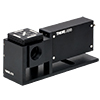
| Photo (Click to Enlarge) | 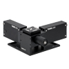 |
 |
|||||
| Number of Channels | 2 | 1 | |||||
| Photocathode Material | Multialkali | ||||||
| Wavelength Range | 185 - 900 nm | ||||||
| Peak Wavelength (λp) | 450 nm | ||||||
| Radiant Sensitivity at λpb |
105 mA/W | ||||||
| PMT Gain (Max) | >1.0 × 10⁷ | ||||||
| Photocathode Active Area | 3.7 mm × 13.0 mm (H × V) |
||||||
| Transimpedance Amplifier | Not Included (Compatible with TIA60) |
||||||
| Mechanical Features | SMA905 Fiber Coupler Internal SM1 Threads (by Disconnecting Fiber Coupler) 1/4" (M6) Counterbored Slots for Table Mounting Interlocking Dovetails Optically Align Additional Channels |
||||||
Standalone Single-Channel Alkali PMTs
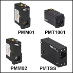
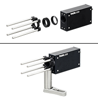
Click to Enlarge
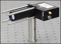
Click to Enlarge

Click for Details
- PMM01: Amplified PMT for 280 - 630 nm with Voltage Output, SM1 Threads, and 30 mm Cage Compatibility
- PMM02: Amplified PMT for 300 - 800 nm with Voltage Output, SM1 Threads, and 30 mm Cage Compatibility
- PMT1001(/M): Amplified PMT for 230 - 920 nm with Voltage Output, SM1 Threads, and 30 mm Cage Compatibility
- PMT1002: Amplified PMT for 230 - 920 nm with Voltage Output and
C-Mount Threads - PMTSS: PMT for 185 - 900 nm with Current Output and C-Mount Threads
Thorlabs' standalone alkali PMTs are offered in four package styles. Each package provides different types of output signals and mechanical mounting features. The Graphs tab contains a plot comparing the radiant sensitivity of each PMT; the radiant sensitivity is closely related to the quantum efficiency. Complete specifications are available in the Specs tab above.
These PMTs feature internal SM1 or C-mount threads, granting them compatibiltiy with our dovetail adapters for 30 mm cage system and SM1 lens tube (sold below). Please contact Tech Support if you wish to integrate these PMTs with existing Thorlabs confocal and multiphoton systems.
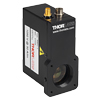
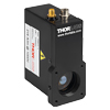
PMM01 and PMM02
The PMM01 and PMM02 modules have an active area of Ø22 mm and Ø21 mm, respectively. Their built-in transimpedance amplifiers allow them to directly provide output voltage signals through an SMA connector. The control voltage that biases the PMT is provided through a 2.5 mm mono jack. A variable voltage source that can provide up to +1.8 V (PMM01) or up to +1.25 V (PMM02) will be needed for bias control. Each module ships with a 2.5 mm mono plug that can be wired by the user to an appropriate low-noise voltage source.
The photocathode is located behind internal SM1 threads. These threads can be used to connect the PMT to SM1 lens tubes, which are useful for reducing scatter into the photocathode from unwanted sources or mounting Ø1" neutral density or bandpass filters. Direct filter mounting is not recommended because the filter will be in contact with the window. In addition, four 4-40 taps for Thorlabs' 30 mm cage system are provided. Three sides of the housing have an 8-32 tapped hole for Ø1/2" and Ø1" post mounting. An 8-32 to M4 thread adapter (Item # AS4M8E) is included for metric setups.
A ±12 V power supply with a region-specific power cord is included with these PMTs. Replacement power supplies are sold below.
PMT1001(/M) and PMT1002
The photocathodes of these PMTs have an active area of Ø8 mm. Their built-in transimpedance amplifiers allow them to directly provide output voltage signals through an SMA connector. The PMTs are powered and controlled through a USB 2.0 mini port, which is required to supply 4.5 to 5.5 VDC at 350 mA typical current. A USB 2.0 type A to mini adapter cable is included to connect the PMT to the computer. Each PMT may be controlled by a computer running the software available from the Software tab, which supports the Windows® 7 and 10 (64-bit) operating systems.
These PMTs are offered in two package styles, providing a range of mechanical mounting options. The PMT1001(/M) features internal SM1 threads, which can be used to connect the PMT to SM1 lens tubes. In addition, the PMT1001(/M) features four 4-40 taps to mount the PMT onto a 30 mm cage system as well as a 1/4"-20 (M6) tapped hole for post mounting, such as with our ∅1" posts. The PMT1002 features internal C-Mount threads, which can be used to connect the PMT to C-Mount extension tubes.
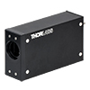
PMTSS
This PMT module has an active area of 3.7 mm × 13.0 mm (H × V). It provides an output current through a BNC connector. Unlike the PMM01 and PMM02 modules, it has no transimpedance amplifier; Thorlabs' TIA60 Transimpedance Amplifier is available separately. The control voltage that biases the PMT is provided through a female M8 x 1 connector. A variable voltage source that can provide up to +1.20 V will be needed for bias control (see the Graphs tab for details). Each module ships with a male M8 x 1 connector with leads that can be wired by the user to an appropriate low-noise voltage source.
The photocathode is located behind internal C-Mount threads. These threads can be used to connect the PMT to C-Mount extension tubes, which are useful for reducing scatter into the photocathode from unwanted sources or mounting Ø1" neutral density or bandpass filters. The threads on the PMT module are not deep enough to directly accommodate a filter with a retaining ring.
No power supply is included with this PMT. The leads on the included male M8 x 1 connector can be wired to a +15 VDC source with a 7 mA current limit. See the Pin Diagrams and Shipping List tabs for details.
Part Number | Description | Price | Availability |
|---|---|---|---|
PMT1001/M | Multialkali Amplified PMT, 230 - 920 nm, SM1 Threads, 30 mm Cage Compatible, M6 Tap | $4,250.91 | 3-5 Days |
PMM01 | Bialkali Amplified PMT, 280 - 630 nm, SM1 Threads, 30 mm Cage Compatible | $2,563.54 | 3-5 Days |
PMM02 | Multialkali Amplified PMT, 300 - 800 nm, SM1 Threads, 30 mm Cage Compatible | $2,928.24 | 3-5 Days |
PMT1002 | Multialkali Amplified PMT, 230 - 920 nm, C-Mount Threads | $4,250.91 | 3-5 Days |
PMTSS | Multialkali PMT, 185 - 900 nm, C-Mount Threads | $3,352.37 | 3-5 Days |
PMT1001 | Multialkali Amplified PMT, 230 - 920 nm, SM1 Threads, 30 mm Cage Compatible, 1/4"-20 Tap | $4,250.91 | 3-5 Days |
Standalone Single-Channel GaAsP PMTs
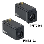
Click to Enlarge
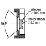
PMT2100 Series Collection Angle
- 300 - 720 nm Spectral Range
- Transimpedance Amplifier Provides Voltage Output
- PMT2101(/M): SM1 Threads, 30 mm Cage Compatible, and 1/4"-20 (M6) Tap for Post Mounting
- PMT2102: C-Mount Threads
To detect low-intensity signals in fluorescence experiments, Thorlabs offers GaAsP PMT modules with an active area of Ø5 mm. The GaAsP photocathode provides a high quantum efficiency in the visible spectrum, resulting in an elevated sensitivity to incoming illumination versus photocathodes composed of alkali metals (see the Overview for a graph of the radiant sensitivity, which is proportional to the quantum efficiency). In addition, these PMT modules utilize a wide collection angle, further enhancing light detection (see the image to the right). Note that, if exposed to high intensity incident light, sensitivity degradation is more likely to occur compared to alkali PMTs.
These PMTs feature a built-in transimpedance amplifier, providing an output voltage through an SMA connector. They are powered and controlled through a USB 2.0 mini port, which is required to supply 4.5 to 5.5 VDC at 350 mA typical current. A USB 2.0 type A to mini adapter cable is included to connect the PMT to the computer. Each PMT may be controlled by a computer running the software available from the Software tab, which supports the Windows® 7 and 10 (64-bit) operating systems.
These PMTs are offered in two package styles, providing a range of mechanical mounting options. The PMT2101(/M) features internal SM1 threads, which can be used to connect the PMT to SM1 lens tubes. In addition, the PMT2101(/M) features four 4-40 taps to mount the PMT onto a 30 mm cage system as well as a 1/4"-20 (M6) tapped hole for post mounting, such as with our ∅1" posts. The PMT2102 features internal C-Mount threads, which can be used to connect the PMT to C-Mount extension tubes.
Thorlabs offers dovetail adapters that can be used to integrate a C-mount- or SM1-threaded PMT into optical assemblies based on our 30 mm cage or SM1 lens tube system. Please contact Tech Support if you wish to integrate these PMTs with existing Thorlabs confocal and multiphoton systems.
Part Number | Description | Price | Availability |
|---|---|---|---|
PMT2101/M | GaAsP Amplified PMT, 300 - 720 nm, SM1 Threads, 30 mm Cage Compatible, M6 Tap | $7,365.11 | Lead Time |
PMT2102 | GaAsP Amplified PMT, 300 - 720 nm, C-Mount Threads | $7,365.11 | 3-5 Days |
PMT2101 | GaAsP Amplified PMT, 300 - 720 nm, SM1 Threads, 30 mm Cage Compatible, 1/4"-20 Tap | $7,365.11 | 3-5 Days |
PMTs for Multi-Channel Detection
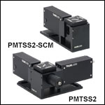
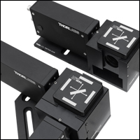
Click to Enlarge
Interlocking Dovetails for Easy Connection of Additional Channels
Click to Enlarge
Removable Filter Cube Top for Holding Dichroic Mirrors and Bandpass Filters
- PMTSS2: Dual-Channel PMT Module with Exchangeable Fluorescence Filter
Cube Insert - PMTSS2-SCM: Add-On Single-Channel PMT Module with Dovetail for Mechanical and Optical Alignment
- Compatible with SMA905 Fiber-Coupled and Free-Space Optical Inputs
- Additional Filter Cube Inserts Available Separately
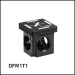
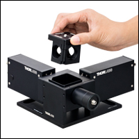
The PMTSS2 Dual-Channel Module and PMTSS2-SCM Add-On Module are designed to help ease detection of signals across multiple spectral channels. The PMTSS2 module incorporates two PMTs (Item # PMTSS, detailed above) and a DFM1T1 Filter Cube Top. This filter cube top can hold one 25 mm x 36 mm dichroic mirror and a Ø25 mm bandpass filter in front of each photocathode, thereby selecting the wavelengths that the PMTs will detect, and it includes a magnetic retention mechanism for easy exchange. The PMTSS2-SCM module is a single-channel add-on for the PMTSS2, which incorporates one PMT and an additional DFM1T1 filter cube top.
The input port of the PMTSS2 module has a fiber collimation assembly with an SMA905 connector, which accepts signals that have been coupled into a multimode fiber patch cable or bundle. A Ø910 µm core, 0.22 NA, SMA905-terminated patch cable for 250 - 1200 nm (bare fiber item # FG910UEC) is included with the module. If desired, the collimation assembly can be unthreaded to allow the module to accept free-space signals. Unthreading this assembly exposes internal SM1 threads that are compatible with our Ø1" lens tubes. The PMTSS2-SCM add-on module does not include a fiber collimation assembly, but it is compatible with the one included with the PMTSS2.
To allow a PMTSS2-SCM module to be added to an existing PMTSS2 setup, the modules' housings include interlocking dovetails that provide mechanical and optical alignment. The installation procedure is illustrated in the animation to the right and requires a 5/64" (2 mm) balldriver or hex key. If using the included fiber input, a maximum of eight channels is recommended in order to prevent beam divergence from causing inefficient signal detection. If using a free-space signal, note that each photocathode's active area is 3.7 mm × 13.0 mm (H × V).
Each PMT provides an output current through a BNC connector. No transimpedance amplifiers are included; Thorlabs' TIA60 Transimpedance Amplifiers are available separately. Each PMT requires a separate control voltage, which is provided through a female M8 x 1 connector. A variable voltage source that can provide up to +1.20 V will be needed for bias control (see the Graphs tab for details). The PMTSS2 module ships with two male M8 x 1 connectors with leads that can be wired by the user to an appropriate low-noise voltage source; the PMTSS2-SCM add-on module ships with one connector.
Each module includes 1/4" (M6) counterbored slots for mounting to an optical table or workstation. Due to the weight of these modules, we only recommend direct table mounting. The PMT can be detached from the rest of the module by loosening a setscrew with a 5/64" (2 mm) balldriver or hex key.
No power supplies are included with these PMT modules. The leads on the included male M8 x 1 connectors can be wired to +15 VDC sources with 7 mA current limits. See the Pin Diagrams and Shipping List tabs for details.
Part Number | Description | Price | Availability |
|---|---|---|---|
PMTSS2 | Dual-Channel Multialkali PMT Module | $9,340.61 | 3-5 Days |
PMTSS2-SCM | Add-On Single-Channel Multialkali PMT Module | $4,642.44 | 3-5 Days |
DFM1T1 | Kinematic 30 mm Cage Cube Insert for Ø25 mm Fluorescence Filters, DFM1 Series, Right-Turning | $296.97 | 3-5 Days |
±12 VDC Regulated Linear Power Supply

- Replacement Power Supply for the PMM01 and PMM02 Modules
- ±12 VDC Power Output
- 2 m (6.6') Cable with LUMBERG RSMV3 Male Connector
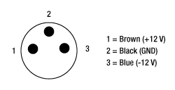
The LDS12B power supply provides a regulated ±12 VDC output for use with our PMM01 and PMM02 modules. It includes an on/off switch with an LED indicator and accepts 100 VAC, 120 VAC, or 230 VAC input voltage, selectable by a switch. As shown in the diagram to the right, the 2 m (6.6') long cord has three pins: one for ground, one for +12 V and one for -12 V. A region-specific power cord is shipped with the unit. This power supply can also be used with the PDA amplified photodetectors, PDB balanced photodetectors, APD avalanche photodetectors, and the FSAC autocorrelator for femtosecond lasers.
Part Number | Description | Price | Availability |
|---|---|---|---|
LDS12B | ±12 VDC Regulated Linear Power Supply, 6 W, 100/120/230 VAC | $93.55 | 3-5 Days |


 Click to Enlarge