

Scan Lenses for Laser Scanning Microscopy

- Telecentric Scanning Lenses with Flat Image Planes
- Minimal Optical Aberrations and Low F-Theta Distortion
- Large Maximum Fields of View up to 28.9 x 28.9 mm2
- Applications Include OCT, Confocal, and Multiphoton Microscopy
CLS-SL
400 to 750 nm
EFL = 70 mm
LSM03-VIS
400 to 700 nm
EFL = 39 mm
LSM02
1250 to 1380 nm
EFL = 18 mm
SL50-3P
800 to 1800 nm
EFL = 50 mm
LSM54-850
750 to 950 nm
EFL = 54 mm
OVERVIEW
 Zemax Files Zemax Files |
|---|
| Click on the red Document icon next to the item numbers below to access the Zemax file download. Our entire Zemax Catalog is also available. |
Features
- Flat Image Plane
- Minimal Optical Aberration Over Image Plane (See Specs Tab for Details)
- Large Field of View
- Low F-Theta Distortion
- Easily Incorporated into Custom-Built Microscopy Systems
- Dispersion Compensators Available Separately for LSM02(-BB), LSM03(-BB), LSM03-VIS, LSM04(-BB), and LSM05(-BB)
| Scan Lens Quick Links | |
|---|---|
| Wavelength | Item # |
| 400 to 700 nm | LSM03-VIS |
| 400 to 750 nm | CLS-SL |
| 450 to 1100 nm | SL50-CLS2 |
| 680 to 1300 nm | SL50-2P2 |
| 750 to 950 nm | LSM54-850 |
| 800 to 1100 nm | LSM02-BB, LSM03-BB, LSM04-BB, and LSM05-BB |
| 800 to 1800 nm | SL50-3P |
| 950 to 1100 nm | LSM54-1050 |
| 1200 to 1400 nm | LSM54-1310 |
| 1250 to 1380 nm | LSM02, LSM03, LSM04, and LSM05 |
Thorlabs' telecentric scan lenses are ideal for use in laser scanning imaging systems and applications such as Optical Coherence Tomography (OCT), confocal laser scanning microscopy, and multiphoton imaging. Telecentric scan lenses produce a flat image plane and a spot size that suffers minimal distortion as the angle of the incident beam with respect to the optical axis of the lens is varied; varying the angle of incidence causes the focal spot to scan over the field of view in the image plane. A low f-theta distortion creates geometrically correct scanned images that do not require extensive post-image processing. A telecentric scan lens path can also maximize the scattered or emitted light that is captured from the sample (the signal) by the detection system. In addition, the spot size in the image plane is nearly constant over the entire field of view (see Specs tab), resulting in image resolution that varies minimally over the scanned area of the sample.
These scan lenses have center wavelengths that extend from the visible to the near-infrared, and they exhibit a range of effective focal lengths, working distances, and scanning distances (see below and the Specs tab for more information). A selection of these lenses offers fields of view equal to or greater than 18 x 18 mm2, and all possess anti-reflection (AR) coatings designed to minimize back reflections from broadband light sources.
Many confocal imaging systems are designed to operate at visible wavelengths, and the CLS-SL and SL50-CLS2 offer two options for visible confocal laser scanning. The wide wavelength range of the SL50-CLS2 (450 - 1100 nm) makes this lens a good choice for applications involving both multiphoton microscopy and visible photoactivation or targeting. We also offer the SL50-2P2 for two photon microscopy (680 - 1300 nm) as well as the SL50-3P for three-photon microscopy (800 - 1800 nm).
Systems operating in the near-infrared include those designed for confocal, multiphoton, and OCT applications. While the LSM family of lenses listed on this page are optimized for OCT applications, these lenses are also used in confocal, multiphoton and other laser scanning imaging systems. The large 6 mm entrance pupils and ±14° scan angles (single-axis scan) of the LSM54-850, LSM54-1050, and LSM54-1310 scan lenses make them ideal for use with larger galvo mirrors that produce more highly deflected beams. The LSM54-850, LSM54-1050, and LSM54-1310 scan lenses have also been optimized to provide a flat field of view, and they are corrected for chromatic aberrations across their wide 200 nm band of operating wavelengths.
Thorlabs' scan lenses and tube lenses are individually corrected for aberrations, and any of these scan lenses may be paired with a tube lens that is also corrected for aberrations.
Click on the links in the table to the right to jump to lenses of interest, or scroll down the page.
SPECS
Specifications
The complete specifications available for each scan lens are provided in the tables below, and definitions of the various parameters follow the tables. Click the blue icons, ![]() , to view the plots. All plots below show theoretical data.
, to view the plots. All plots below show theoretical data.
Lenses with Wavelength Ranges Starting Between 400 and 450 nm
| Item # | LSM03-VIS | CLS-SL | SL50-CLS2 | |
|---|---|---|---|---|
| Optical Specifications | ||||
| Wavelength Range | 400 to 700 nm | 400 to 750 nm | 450 to 1100 nm | |
| Effective Focal Length (EFL) | 39 mm | 70.0 mm | 50 mm | |
| Entrance Pupil Diametera | 4 mm | 4 mm | 4 mm | |
| Parfocal Distance | 50.7 mm | - | 77.3 mm | |
| Lens Working Distance | 25.1 mm | 54 mm | 26.4 mm | |
| Scanning Distanceb | 29.0 mm ± 5 mm | 58 ± 6 mm | 37.8 ± 4 mm | |
| Optical Scan Anglec (Single-Axis Scan) |
Maximum | ±10.6° | ±11° FN26.9 | ±11.5° |
| Difffraction Limited | ±8.4° (543 nm) | ±10.4° (486 to 750 nm) FN25.5d ±9.4° (400 to 750 nm) FN23d |
±7.5° (at 486.1 nm) ±9° (at 587.6 nm) ±11.5° (656.6 - 1100 nm) |
|
| Optical Scan Anglec (Two-Axis Scan) |
Maximum | ±7.5° x ±7.5° | ±7.8° x ±7.8° | ±8.1° x ±8.1° |
| Diffraction Limited | ±5.1° x ±5.1° (543 nm) | ±7.35° x ±7.35° (486 to 750 nm) ±6.6° x ±6.6° (400 to 750 nm) |
±5.3° x ±5.3° (at 486.1 nm) ±6.3° x ±6.3° (at 587.6 nm) ±8.1° x ±8.1° (656.6 nm - 1100 nm) |
|
| Spot Size Plotsa |
Two-Axis Scan:  Single-Axis Scan:  |
Single-Axis Scan: |
Single-Axis Scan: |
|
| Field of Viewe |
Maximum | 10.3 x 10.3 mm2 (Two-Axis Scan) | 19 x 19 mm2 FN25.5 (Two-Axis Scan) | 14.1 x 14.1 mm2 FN20 (Two-Axis Scan) |
| Diffraction Limited | 6.9 x 6.9 mm2 | 18 x 18 mm2 FN25.5 (486 to 750 nm) 16 x 16 mm2 FN23 (400 to 750 nm) |
9.2 x 9.2 mm2 FN13 (at 486.1 nm) 11.1 x 11.1 mm2 FN15.7 (at 587.6 nm) 14.1 x 14.1 mm2 FN20 (656.5 - 1100 nm) |
|
| Depth of Viewe (Twice Rayleigh Length) | 0.28 mm | - | - | |
| F-Theta Distortione | <0.8% | <0.05% | <0.2% | |
| Field Curvaturee | <0.3 mm | <0.7 mm for FN25d <0.5 mm for FN21d |
<500 µm | |
| Axial Color | 60 µm (400 to 700 nm) |
<50 µm (400 to 750 nm) |
<80 µm for 450 - 1100 nm <25 µm for 680 - 1100 nm Plot: |
|
| Lateral Color Shift | 15 µm (400 to 700 nm) |
- | - | |
| f/# | 9.8 | 17.5 | 12.5 | |
| Transmittance | - | |||
| Reflectance |  |
- | - | |
| Dimensional Specifications | ||||
| Mounting Thread (External) | M25 x 0.75 | SM2 (2.035"-40), Both Ends | SM30 (M30.5 x 0.5) | |
| Thread Length | 4.4 mm (0.17") | 6.0 mm (0.24") | 3.0 mm (0.12") | |
| Barrel Diameter | 34 mm (1.35") | 56.0 mm (2.20") | 35.0 mm (1.38") | |
| Length of Barrel | 25.5 mm (1.00") | 55.5 mm (2.19") | 50.9 mm (2.00") | |
Lenses with Wavelength Ranges Starting Between 680 and 800 nm
| Item # | SL50-2P2 | LSM54-850 | LSM02-BB | LSM03-BB | LSM04-BB | LSM05-BB | |
|---|---|---|---|---|---|---|---|
| Optical Specifications | |||||||
| Wavelength Range | 680 to 1300 nm | 750 to 950 nm | 800 to 1100 nma | ||||
| Effective Focal Length (EFL) | 50 mm | 54 mm | 18 mm | 36 mm | 54 mm | 110 mm | |
| Entrance Pupil Diameterb | 5 mm | 6 mm | 4 mm | 8 mm | |||
| Parfocal Distance | 77.3 mm | 112 mm | 30.7 mm | 50.5 mm | 80.7 mm | 154.8 mm | |
| Lens Working Distance | 26.4 mm | 64 mm | 7.5 mm | 25.1 mm | 42.3 mm | 93.8 mm | |
| Scanning Distancec | 37.8 ± 4 mm | 17.8 mm ± 7.5 mm | 16.1 mm ± 5 mm | 18.9 mm ± 5 mm | 18.9 mm ± 5 mm | 75.5 mm ± 5 mm | |
| Optical Scan Angled (Single-Axis Scan) |
Maximum | ±11.5° | ±14.0° | ±10.6° | ±10.6° | ±10.6° | ±10.6° |
| Diffraction Limited | ±7.2° (at 680 nm) ±8° (at 800 nm) ±11.5° (1000 - 1300 nm) |
±13.6° | ±10.2° (850 nm) ±10.6° (1050 nm) |
±9.0° (850 nm) ±9.7° (1050 nm) |
±10.6° (850 nm) ±10.6° (1050 nm) |
±7.2° (850 nm) ±8.1° (1050 nm) |
|
| Optical Scan Angled (Two-Axis Scan) |
Maximum | ±8.1° x ±8.1° | ±10.0° x ±10.0° | ±7.5° x ±7.5° | ±7.5° x ±7.5° | ±7.5° x ±7.5° | ±7.5° x ±7.5° |
| Diffraction Limited | ±5.3° x ±5.3° (at 680 nm) ±6.3° x ±6.3° (at 800 nm) ±8.1° x ±8.1° (1000 nm - 1300 nm) |
±8.4° x ±8.4° | ±5.1° x ±5.1° (850 nm) ±5.9° x ±5.9° (1050 nm) |
±6.3° x ±6.3° (850 nm) ±6.8° x ±6.8° (1050 nm) |
±7.5° x ±7.5° (850 nm) ±7.5° x ±7.5° (1050 nm) |
±4.9° x ±4.9° (850 nm) ±5.5° x ±5.5° (1050 nm) |
|
| Spot Size Plotsb |
Single-Axis Scan: |
Two-Axis Scan:  Single-Axis Scan: |
Two-Axis Scan: 850 nm:  1050 nm:  Single-Axis Scan: 850 nm:  1050 nm:  |
Two-Axis Scan: 850 nm:  1050 nm:  Single-Axis Scan: 850 nm:  1050 nm:  |
Two-Axis Scan: 850 nm:  1050 nm:  Single-Axis Scan: 850 nm:  1050 nm:  |
Two-Axis Scan: 850 nm:  1050 nm:  Single-Axis Scan: 850 nm:  1050 nm:  |
|
| Field of Viewe |
Maximum | 14.1 x 14.1 mm2 FN20 | 18.8 x 18.8 mm2 (Two-Axis Scan) |
4.7 x 4.7 mm2 (Two-Axis Scan) |
9.4 x 9.4 mm2 (Two-Axis Scan) |
14.1 x 14.1 mm2 (Two-Axis Scan) |
28.9 x 28.9 mm2 (Two-Axis Scan) |
| Diffraction Limited | 8.9 x 8.9 mm2 FN12.6 (at 680 nm) 9.9 x 9.9 mm2 FN14 (at 800 nm) 14.1 x 14.1 mm2 FN20 (1000 - 1300 nm) |
15.8 x15.8 mm2 | 3.2 x 3.2 mm2 (850 nm) 3.7 x 3.7 mm2 (1050 nm) |
7.9 x 7.9 mm2 (850 nm) 8.6 x 8.6 mm2 (1050 nm) |
14.1 x 14.1 mm2 (850 nm) 14.1 x 14.1 mm2 (1050 nm) |
18.8 x 18.8 mm2 (850 nm) 21.1 x 21.1 mm2 (1050 nm) |
|
| Depth of Viewe (Twice Rayleigh Length) |
- | 0.17 mm | 0.09 mm (850 nm) 0.11 mm (1050 nm) |
0.36 mm (850 nm) 0.45 mm (1050 nm) |
0.81 mm (850 nm) 1.01 mm (1050 nm) |
0.85 mm (850 nm) 1.05 mm (1050 nm) |
|
| F-Theta Distortione | <0.2% | <0.3% | <0.9% | <0.2% | <1.1% | <0.4% | |
| Field Curvaturee | <500 µm | <0.3 mm | <0.1 mm | <0.2 mm | <0.2 mm | <0.5 mm | |
| Axial Color | <25 µm for 680 - 1100 nm Plot: |
210 µm (750 to 950 nm) |
5 µm (810 to 890 nm) 10 µm (1000 to 1100 nm) |
15 µm (810 to 890 nm) 10 µm (1000 to 1100 nm) |
30 µm (810 to 890 nm) 10 µm (1000 to 1100 nm) |
30 µm (810 to 890 nm) 150 µm (1000 to 1100 nm) |
|
| Lateral Color Shift | - | 5 µm (750 to 950 nm) |
5 µm (810 to 890 nm) 5 µm (1000 to 1100 nm) |
10 µm (810 to 890 nm) 10 µm (1000 to 1100 nm) |
20 µm (810 to 890 nm) 20 µm (1000 to 1100 nm) |
10 µm (810 to 890 nm) 30 µm (1000 to 1100 nm) |
|
| f/# | 12.5 (4 mm Entrance Pupil) 10 (5 mm Entrance Pupil) |
9.0 | 4.5 | 9.0 | 13.5 | 13.8 | |
| Transmittance | - | ||||||
| Reflectance | - | - |  a a |
||||
| Dimensional Specifications | |||||||
| Mounting Thread (External) | SM30 (M30.5 x 0.5) | M25 x 0.75 | M25 x 0.75 | SM2 (2.035"-40) | |||
| Thread Length | 3.0 mm (0.12") | 4.7 mm (0.19") | 4.4 mm (0.17") | 4.5 mm (0.18") | 4.7 mm (0.19") | 5.5 mm (0.22") | |
| Barrel Diameter | 35.0 mm (1.38") | 43.0 mm (1.40") | 33 mm (1.30") | 34 mm (1.35") | 34 mm (1.35") | 59.5 mm (2.34") | |
| Length of Barrel | 50.9 mm (2.00") | 48.0 mm (1.89") | 23.2 mm (0.91") | 25.5 mm (1.00") | 38.25 mm (1.51") | 61.0 mm (2.40") | |
Lenses with Wavelength Ranges Starting Between 800 and 1250 nm
| Item # | SL50-3P | LSM54-1050 | LSM54-1310 | LSM02 | LSM03 | LSM04 | LSM05 | |
|---|---|---|---|---|---|---|---|---|
| Optical Specifications | ||||||||
| Wavelength Range | 800 to 1800 nm | 950 to 1150 nm | 1200 to 1400 nm | 1250 to 1380 nm | ||||
| Effective Focal Length | 50 mm | 54 mm | 54 mm | 18 mm | 36 mm | 54 mm | 110 mm | |
| Entrance Pupil Diametera | 5 mm | 6 mm | 6 mm | 4 mm | 4 mm | 4 mm | 8 mm | |
| Parfocal Distance | 77.3 mm | 112 mm | 112 mm | 30.7 mm | 50.6 mm | 80.8 mm | 154.8 mm | |
| Lens Working Distance | 26.4 mm | 64 mm | 64 mm | 7.5 mm | 25.1 mm | 42.3 mm | 93.8 mm | |
| Scanning Distanceb | 37.8 ± 4 mm | 17.8 mm ± 7.5 mm | 17.8 mm ± 7.5 mm | 16.1 mm ± 5 mm | 18.9 mm ± 5 mm | 18.9 mm ± 5 mm | 75.5 mm ± 5 mm | |
| Optical Scan Anglec (Single-Axis Scan) |
Maximum | ±11.5° | ±14.0° | ±14.0° | ±10.6° | ±10.6° | ±10.6° | ±10.6° |
| Diffraction Limited | ±8.0° (at 800 nm) ±8.5° (at 900 nm) ±11.5° (1000 - 1800 nm) |
±14.0° | ±14.0° | ±10.6° | ±10.6° | ±10.6° | ±9.0° | |
| Optical Scan Anglec (Two-Axis Scan) |
Maximum | ±8.5° x ±8.5° | ±10.0° x ±10.0° | ±10.0° x ±10.0° | ±7.5° x ±7.5° | ±7.5° x ±7.5° | ±7.5° x ±7.5° | ±7.5° x ±7.5° |
| Diffraction Limited | ±6.0° x ±6.0° (at 900 nm) |
±9.5° x ±9.5° | ±10.0° x ±10.0° | ±6.7° x ±6.7° | ±7.4° x ±7.4° | ±7.5° x ±7.5° | ±6.2° x ±6.2° | |
| Spot Size Plotsa |
Single-Axis Scan:  |
Two-Axis Scan:  Single-Axis Scan:  |
Two-Axis Scan:  Single-Axis Scan:  |
Two-Axis Scan:  Single-Axis Scan:  |
Two-Axis Scan: Single-Axis Scan:  |
Two-Axis Scan: Single-Axis Scan:  |
Two-Axis Scan: Single-Axis Scan:  |
|
| Field of Viewd |
Maximum | 14.1 x 14.1 mm2 FN20 | 18.8 x 18.8 mm2 (Two-Axis Scan) |
18.8 x 18.8 mm2 (Two-Axis Scan) |
4.7 x 4.7 mm2 (Two-Axis Scan) |
9.4 x 9.4 mm2 (Two-Axis Scan) |
14.1 x 14.1 mm2 (Two-Axis Scan) |
28.9 x 28.9 mm2 (Two-Axis Scan) |
| Diffraction Limited | 10.5 x 10.5 mm2 FN14.8 (at 900 nm) 14.1 x 14.1 mm2 FN20 (1000 - 1800 nm) |
18.0 x 18.0 mm2 | 18.8 x 18.8 mm2 | 4.2 x 4.2 mm2 | 9.3 x 9.3 mm2 | 14.1 x 14.1 mm2 | 23.8 x 23.8 mm2 | |
| Depth of Viewd (Twice Rayleigh Length) |
- | 0.22 mm | 0.27 mm | 0.14 mm | 0.56 mm | 1.26 mm | 1.32 mm | |
| F-Theta Distortiond | <0.2% | <0.25% | <0.25% | <0.9% | <0.2% | <1.1% | <0.4% | |
| Field Curvature | <700 µm | <0.3 mm | <0.3 mm | <0.1 mm | <0.2 mm | <0.2 mm | <0.5 mm | |
| Axial Color | <250 µm (800 to 1800 nm) Plot:  |
50 µm (950 to 1150 nm) |
200 µm (1200 to 1400 nm) |
25 µm (1250 to 1380 nm) |
5 µm (1250 to 1380 nm) |
50 µm (1250 to 1380 nm) |
300 µm (1250 to 1380 nm) |
|
| Lateral Color Shift | - | 30 µm (950 to 1150 nm) |
50 µm (1200 to 1400 nm) |
10 µm (1250 to 1380 nm) |
10 µm (1250 to 1380 nm) |
25 µm (1250 to 1380 nm) |
60 µm (1250 to 1380 nm) |
|
| f/# | 10 (5 mm Entrance Pupil) |
9.0 | 9.0 | 4.5 | 9.0 | 13.5 | 13.8 | |
| Transmittance | - | |||||||
| Reflectance | - |  |
||||||
| Dimensional Specifications | ||||||||
| Mounting Thread (External) | SM30 (M30.5 x 0.5) | M25 x 0.75 | M25 x 0.75 | M25 x 0.75 | SM2 (2.035"-40) | |||
| Thread Length | 3.0 mm (0.12") | 4.7 mm (0.19") | 4.7 mm (0.19") | 4.4 mm (0.17") | 4.5 mm (0.18") | 4.7 mm (0.19") | 5.5 mm (0.22") | |
| Barrel Diameter | 35.0 mm (1.38") | 43.0 mm (1.40") | 43.0 mm (1.40") | 33 mm (1.30") | 34 mm (1.35") | 34 mm (1.35") | 59.5 mm (2.34") | |
| Length of Barrel | 50.9 mm (2.00") | 48.0 mm (1.89") | 48.0 mm (1.89") | 23.2 mm (0.91") | 25.5 mm (1.00") | 38.25 mm (1.51") | 61.0 mm (2.40") | |
Definitions of Key Parameters

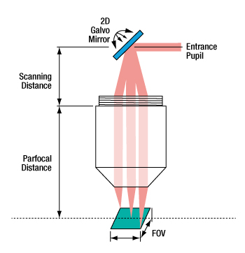
Scanning Distance (SD): The SD is the distance between the aperture plane, where the EP lies, and the back mounting plane of the objective, which is defined as the base of the mounting threads. For these lenses, the mounting plane is the shoulder adjacent to the threads, or thread mounting plane, of the lens. When two galvo mirrors are used, the aperture plane occurs midway between the two mirrors. When one galvo mirror is used, the pivot point of the single mirror coincides with the aperture plane. See the Application Info tab for more details.
Scan Angle (SA): After being routed from the galvo mirror(s) the laser beam is incident on the lens at an angle. This angle, measured with respect to the optical axis of the lens, is the scan angle. When listed in the specification table, it indicates the range of maximum allowed scan angles.
Parfocal Distance (PD): The PD is the distance from the scan lens mounting plane to the front focal plane of the scan lens.
Working Distance (WD or LWD): The distance between the tip of the scan lens housing and the front focal plane of the scan lens is defined as the WD.
Field of View (FOV): The FOV is the maximum size of the area on the sample that can be imaged with a resolution equal to or better than the stated resolution of the scan lenses. This assumes the proper utilization of the scan lenses in the optical system. During operation, the spot positions scan through the FOV.
Depth of View (DOV): The DOV parameter corresponds to the distance between the parallel planes on either side of the front focal plane where the beam spot diameter is √2 greater than it is at the front focal plane. This parameter is of interest when tube lenses are not used in the optical system design and the front focal place is also the sample plane, as is generally the case for OCT. When a tube lens is paired the scan lens, the image plane is located between the scan and the tube lens; the depth of field at the sample is then controlled by the microscope objective.
Spot Size Data
Spot sizes formed in the image plane are typically of more interest to OCT system design than to other laser scanning microscopy system designs. This is because in most OCT systems the image plane is also the sample plane. In other laser scanning applications, scan lenses are routinely paired with tube lenses and the image plane of the scan lens does not coincide with the sample plane.
Spot size plots for these lenses may be viewed by clicking on the blue icons, ![]() , in the preceding tables. Spot size data are calculated for simulated two-axis and single-axis scans; for the two-axis case a system with two galvo mirrors is simulated, and for the single-axis case a system with a single galvo mirror is simulated. The location of the entrance pupil, which is positioned at the aperture plane, varies depending on whether one or two mirrors are used. When two galvo mirrors are used, the aperture plane is located midway between two galvo mirrors, as is shown in the right image of the Application Info tab. When a single galvo mirror is used, the aperture plane falls at the pivot point of the mirror, as is shown in the left image of the Application Info tab.
, in the preceding tables. Spot size data are calculated for simulated two-axis and single-axis scans; for the two-axis case a system with two galvo mirrors is simulated, and for the single-axis case a system with a single galvo mirror is simulated. The location of the entrance pupil, which is positioned at the aperture plane, varies depending on whether one or two mirrors are used. When two galvo mirrors are used, the aperture plane is located midway between two galvo mirrors, as is shown in the right image of the Application Info tab. When a single galvo mirror is used, the aperture plane falls at the pivot point of the mirror, as is shown in the left image of the Application Info tab.
The two-axis scan gives detailed information about the variation in spot size and spot position over an entire two-dimensional range of scan angles; spot sizes over entire image plane are plotted. These data are calculated for a single wavelength (the center wavelength of the lens) and presented as a 3D plot, with the spot size data plotted on the vertical axis.
The 2D single-axis scan graph contains three curves corresponding to: the center wavelength, the minimum specified wavelength, and the maximum specified wavelength. Together they illustrate the dependence of spot size on wavelength. The single-axis scan graphs plot spot size and spot position over a one-dimensional range of scan angles; the spot positions scan a line through the image plane. Because the aperture plane is not located in the same place for the Two-Axis and Single-Axis Scan plots, the data in the Single-Axis plot is not an exact cross section of the Two-Axis Scan plot data. The single-axis scan data were simulated using a system focused at the center wavelength of the lens; the system was not individually focused at each of the three wavelengths.
APPLICATION INFO
Scan lenses are used in a variety of laser imaging systems, including confocal laser scanning microscopy, optical coherence tomography (OCT), and multiphoton imaging systems. In these applications, a laser beam incident on the back aperture (entrance pupil) of the lens is scanned through a range of angles. This translates the position of the spot formed in the image plane across the lens' field of view. In the case of non-telecentric lenses, this approach to scanning the focal spot through the image plane would introduce severe aberrations that would significantly degrade the quality of the resulting image. Telecentric scan lenses are designed to create a uniform spot size in the image plane at every scan position, which allows a high-quality image of the sample to be formed. Plots showing the spot size and scan position as a function of scan angle are included in the Specs tab.
In general, laser scanning microscopy systems pair a scan lens with a tube lens to create an infinity-corrected optical system. However, most OCT systems are designed to use the scan lens without a tube lens. The CLS-SL, SL50-CLS2, SL50-2P2, and SL50-3P lenses were optimized for use in Thorlabs' confocal laser scanning and multiphoton microscopy systems, and the LSM family of lenses were optimized to be used in OCT imaging systems. A brief discussion of scanning systems implemented with and without tube lenses follows.
Click to Enlarge
The tube and scan lens schematic above shows the lens spacing for the SL50-CLS2 scan lens used with a 200 mm focal length telecentric tube lens. Note that for the SL50-CLS2, the entrance pupil at the scan plane is a maximum of Ø4 mm.
Scan Lenses Implemented in General Laser Scanning Microscopy Applications
The image to the right shows the proper spacing of the scan and tube lenses for laser scanning microscopy. The scanning mirror, which is located at the left of the image at the scan plane, directs the laser beam through the scan lens. The angle at which the laser beam is incident on the scan lens determines the position of the focal spot in the intermediate image plane, which is located between the scan lens and the TTL200MP tube lens. The tube lens is positioned so that it collects and collimates the light (the focus is at infinity). The collimated light is collected by the objective, which brings it to a focus on the sample plane. Light scattered or emitted from the sample plane is collected by the objective and directed to a detector. The image below and to the left shows a CLS-SL scan lens paired with a tube lens; clicking on the image shows the correct spacing for using the CLS-SL with the ITL200 tube lens.
An attractive feature of this optical system design is the collimated light that is produced as a result of pairing the scan lens with the tube lens. With the light from the tube lens focusing at infinity, it is possible to move the position of the objective with respect to the tube lens without impacting the image quality at the sample plane. This imparts considerable flexibility to the design of the optical system. If no tube lens were used, the scan lens would also function as the objective and the intermediate image plane would become the sample plane. It would not be possible to move the image plane much with respect to the scan lens while maintaining image quality.
The image below and to the right shows the relationship between the scan distance and the objective distance. In a perfect 4f optical system (using the CLS-SL as an example), d1 = 52 mm (minimum scan distance) and d2 = f2. However, in many practical cases the system is slightly deviated from this perfect alignment. For instance, in many commercial microscopes, the objective distance (d2) is not the same as the focal length (f2), so there may be a need to adjust distances. The figure below and to the right shows the scan and objective distance moved by some small distance δ1 and δ2, respectively. The relationship between these values is δd1 = -δd2*(f1/f2)2.

Click for Details
CLS-SL Tube Lens integration with the ITL200 and an objective in a laser scanning system.

Click to Enlarge
A diagram showing lens placement for a general laser scanning system.
Scan Lenses Implemented in OCT
When designing an imaging system that uses an LSM scan lens in an OCT configuration, it is important to accommodate the design wavelength, parfocal distance, scanning distance, entrance pupil, and scan angle specifications in order to maximize the image quality (see the Specs tab for scan lens specifications and definitions). In general, the larger the input beam diameter, the smaller the focused spot size. However, due to the effects of vignetting and/or increased aberrations, the range of scan angles decreases as the diameter of the beam increases. Beams smaller than the entrance pupil specification will result in spot sizes larger than those specified in the Specs tab, and beams with larger diameters will be clipped.
For imaging systems with a single galvo mirror the center of the scan lens' entrance pupil is coincident with the pivot point of the galvo mirror. When a single galvo mirror is used, the scanning distance is measured from the mounting surface of the lens to the pivot point of the mirror. This is shown in the image at bottom-left.
If the imaging system uses two galvo mirrors (one to scan in the X direction and one to scan in the Y direction), the entrance pupil is located between the two galvo mirrors, as is shown in the image at bottom-right. The scanning distance is then the distance from the mounting surface of the lens to the pivot point of the mirror closest to the lens (d1) plus the distance from the pivot point of that mirror to the entrance pupil (d2). It is important to minimize the distance between the two galvo mirrors, because when the entrance pupil and beam steering pivot point are not coincident, the quality of the image is degraded. This is principally due to the variation in the optical path length as the beam is scanned over the sample. Below are schematics for an imaging system containing one and two galvo mirrors.
When one galvo mirror is used, the entrance pupil is located
at the pivot point of the mirror.
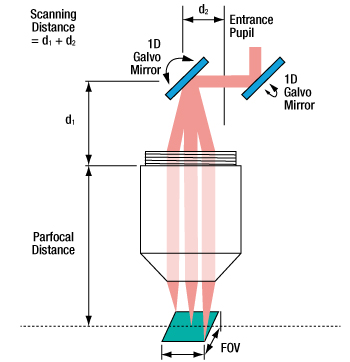
When two galvo mirrors are used, the entrance pupil is located between the mirrors.
400 to 700 nm Wavelength Range
| Key Specificationsa,b | |
|---|---|
| Wavelength Range | 400 to 700 nm |
| Effective Focal Length | 39 mm |
| Lens Working Distance | 25.1 mm |
| Field of View, Maximum |
10.3 x 10.3 mm2 |
| Field of View, Diffraction Limited | 6.9 x 6.9 mm2 |
| Spot Size Plot, 543 nm (Two-Axis Scan) |
|
| Reflectance | |
| Mounting Threads (External) | M25 x 0.75 |
- For detailed specs, please refer to the Specs tab.
- Click the blue icons,
 , to view the plots.
- Design Optimized for OCT Imaging Systems
- Entrance Pupil: 4 mm
- Scan Angle Range: ±10.6° (Maximum, Single Axis)
- External M25 x 0.75 Mounting Threads
While this lens design is optimized for OCT imaging, it may also be used in a variety of laser scanning microscopy applications. The LSM03-VIS scan lens is designed and AR coated for imaging over the visible wavelength range (400 to 700 nm). Key specifications for this lens are listed to the right; see the Specs tab for complete specifications.
The external M25 x 0.75 threading can be adapted to Thorlabs' standard SM1 (1.035"-40) threading by using an SM1A12 adapter. An RMSA2 adapter allows the scan lens to be used with RMS-threaded (0.800"-36) components.
For OCT imaging systems that utilize this scan lens as a primary objective element, we offer the LSM03DC-VIS dispersion compensator.
Part Number | Description | Price | Availability |
|---|---|---|---|
LSM03-VIS | Scan Lens, 400 to 700 nm, EFL=39 mm | $1,138.02 | Today |
400 to 750 nm Wavelength Range, Large Field of View

| Key Specificationsa,b | |
|---|---|
| Wavelength Range | 400 to 750 nm |
| Effective Focal Length | 70.0 mm |
| Lens Working Distance | 54 mm |
| Field of View, Maximum | 19 x 19 mm2 |
| Field of View, Diffraction Limited | 18 x 18 mm2 (486 to 750 nm) 16 x 16 mm2 (400 to 750 nm) |
| Spot Size Plot: 405, 436, 486, 587, 633, and 750 nm |
 |
| Transmittance | |
| Mounting Threads (External) | SM2 (2.035"-40) |
- For detailed specs, please refer to the Specs tab.
- Click the blue icons, , to view the plots.
- Design Optimized for Confocal Laser Scanning Microscopy Systems
- Entrance Pupil: 4 mm
- Large Maximum Field of View: 19 x 19 mm2
- External SM2 (2.035"-40) Mounting Threads
The CLS-SL scan lens is designed and AR coated for point-by-point laser scanning imaging over the visible wavelength range (400 to 750 nm). This scan lens, originally designed for Thorlabs' Confocal Laser Scanning Microscopy Systems, can be easily integrated into customer-designed laser scanning systems using the external SM2 (2.035"-40) threads on both ends. We recommend pairing this scan lens with our ITL200 tube lens and one of our objectives.
Please note that even though the CLS-SL has a symmetric housing, it is not bi-directional. When the housing's engraving is right-side-up, the light should enter the lens from the top. For additional specifications, please see the Specs tab.
Part Number | Description | Price | Availability |
|---|---|---|---|
CLS-SL | Scan Lens with Large Field of View, 400 to 750 nm, EFL=70 mm | $3,049.40 | Today |
450 to 1100 nm Wavelength Range
| Key Specificationsa,b | |
|---|---|
| Wavelength Range | 450 to 1100 nm |
| Effective Focal Length | 50 mm |
| Lens Working Distance | 26.4 mm |
| Field of View, Diffraction Limited |
9.2 x 9.2 mm2 (486.1 nm) 11.1 x 11.1 mm2 (587.6 nm) 14.1 x 14.1 mm2 (656.6 -1100 nm) |
| Transmittance | |
| Mounting Threads (External) | SM30 (M30.5 x 0.5) |
- For detailed specs, please refer to the Specs tab.
- Click the blue icons, , to view the plots.
- Design Optimized for Laser Scanning Microscopy Systems
- Telecentric When Paired with a TTL200MP Tube Lens
- Entrance Pupil: 4 mm
- Large Maximum Field of View: 14.1 x 14.1 mm2 for 656.6 - 1100 nm
- External SM30 (M30.5 x 0.5) Mounting Threads
The SL50-CLS2 scan lens is designed and AR coated for point-by-point laser scanning imaging over the visible and NIR wavelength ranges (450 - 1100 nm). This broad wavelength range enables applications involving both multiphoton microscopy and visible photoactivation or targeting. This scan lens can easily be integrated into customer-designed systems using the external SM30 mounting threads on one end. The SM1A70 internal SM30 to external SM1 (1.035"-40) adapter (sold below) positions this lens to at the correct distance from the output port of an LSK-GG4(/M), LSK-GR08(/M), or LSK-GR12(/M) galvo scan head. The SM2A11 internal SM30 to external SM2 (2.035"-40) adapter is available for adapting this lens to our SM2 lens tubes. This lens is designed to be telecentric when paired with a TTL200MP tube lens and one of our objectives, as shown in the diagram on the Application Info tab.
The housing is engraved with an arrow next to the text "EP" (Entrance Pupil) indicating the end of the housing that should face the scanning system.
Part Number | Description | Price | Availability |
|---|---|---|---|
SL50-CLS2 | Scan Lens, 450 to 1100 nm, EFL=50 mm | $3,575.65 | Today |
680 to 1300 nm Wavelength Range

| Key Specificationsa,b | |
|---|---|
| Wavelength Range | 680 to 1300 nm |
| Effective Focal Length | 50 mm |
| Lens Working Distance | 26.4 mm |
| Field of View, Diffraction Limited |
8.9 x 8.9 mm2 (680 nm) 9.9 x 9.9 mm2 (800 nm) 14.1 x 14.1 mm2 (1000 - 1300 nm) |
| Transmittance | |
| Mounting Threads (External) | SM30 (M30.5 x 0.5) |
- For detailed specs, please refer to the Specs tab.
- Click the blue icons, , to view the plots.
- Design Optimized for Two-Photon Laser Scanning Microscopy Systems
- Telecentric When Paired with a TTL200MP Tube Lens
- Entrance Pupil: Up to 5 mm
- Large Maximum Field of View: 14.1 x 14.1 mm2 from 1000 to 1300 nm
- External SM30 (M30.5 x 0.5) Mounting Threads
The SL50-2P2 scan lens is designed and AR coated for point-by-point laser scanning imaging over the NIR wavelength range (680 - 1300 nm). This scan lens is used in our Bergamo® Multiphoton Imaging Microscope and can easily be integrated into customer-designed systems using the external SM30 mounting threads on one end. The SM1A70 internal SM30 to external SM1 (1.035"-40) adapter (sold below) positions this lens to at the correct distance from the output port of an LSK-GG4(/M), LSK-GR08(/M), or LSK-GR12(/M) galvo scan head. The SM2A11 internal SM30 to external SM2 (2.035"-40) adapter is available for adapting this lens to our SM2 lens tubes. This lens is designed to be telecentric when paired with a TTL200MP tube lens and one of our objectives, as shown in the diagram on the Application Info tab.
The housing is engraved with an arrow next to the text "EP" (Entrance Pupil) indicating the end of the housing that should face the scanning system.
Part Number | Description | Price | Availability |
|---|---|---|---|
SL50-2P2 | Scan Lens, 680 to 1300 nm, EFL=50 mm | $3,575.65 | Today |
750 to 950 nm Wavelength Range, Large Field of View
| Key Specificationsa,b | |
|---|---|
| Wavelength Range | 750 to 950 nm |
| Effective Focal Length | 54 mm |
| Lens Working Distance | 64 mm |
| Field of View, Maximum | 18.8 x 18.8 mm2 |
| Field of View, Diffraction Limited | 15.8 x 15.8 mm2 |
| Spot Size Plot, 850 nm (Two-Axis Scan) |
|
| Transmittance | |
| Mounting Threads (External) | M25 x 0.75 |
- For detailed specs, please refer to the Specs Tab.
- Click the blue icons, , to view the plots.

- Design Optimized for OCT Imaging Systems
- Large Entrance Pupil: 6 mm
- Wide Scan Angle Range: ±14.0° (Maximum, Single Axis)
- Large Maximum Field of View: 18.8 x 18.8 mm2
- Minimum Spot Size: 14 µm at 850 nm (See Table at Right)
While the LSM54-850 lens is optimized for OCT imaging, it may also be used in a variety of laser scanning microscopy applications. Compared with many of our other LSM scan lenses, the LSM54 lenses, with their larger entrance pupils and range of scan angles, offer better compatibility with galvo mirrors that are larger and produce more highly deflected beams. Other features made possible through optimized optical design and an increased number of refractive elements include improved chromatic correction and the ability to operate over a wide spectral range. For systems operating in the 950 to 1150 nm or 1200 to 1400 nm wavelength ranges, the LSM54-1050 or LSM54-1310 lenses, respectively, provide similar performance.
The table at right includes key specifications for the LSM54-850 lens, including a representative plot showing the small spot size and the spot position in the image plane as a function of all scanned angles at a wavelength of 850 nm. Click on the blue icons, ![]() , to view the spot size and transmittance plots. For additional specifications, please see the Specs tab.
, to view the spot size and transmittance plots. For additional specifications, please see the Specs tab.
The external M25 x 0.75 threading can be adapted to Thorlabs' standard SM1 (1.035"-40) threading by using an SM1A12 adapter. An RMSA2 adapter allows the scan lens to be used with RMS-threaded (0.800"-36) components.
For OCT imaging systems that utilize this scan lens as a primary objective element, we offer the LSM54DC1 dispersion compensator.
Part Number | Description | Price | Availability |
|---|---|---|---|
LSM54-850 | Scan Lens, 750 to 950 nm, EFL=54 mm | $1,822.27 | Today |
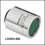
800 nm to 1100 nm Wavelength Range
| Key Specificationsa,b | ||||
|---|---|---|---|---|
| Item # | LSM02-BB | LSM03-BB | LSM04-BB | LSM05-BB |
| Wavelength Range | 800 to 1100 nm | |||
| Effective Focal Length | 18 mm | 36 mm | 54 mm | 110 mm |
| Lens Working Distance | 7.5 mm | 25 mm | 42 mm | 94 mm |
| Field of View, Maximum | 4.7 x 4.7 mm2 | 9.4 x 9.4 mm2 | 14.1 x 14.1 mm2 | 28.9 x 28.9 mm2 |
| Field of View, Diffraction Limited |
3.2 x 3.2 mm2 (850 nm) 3.7 x 3.7 mm2 (1050 nm) |
7.9 x 7.9 mm2 (850 nm) 8.6 x 8.6 mm2 (1050 nm) |
14.1 x 14.1 mm2 (850 nm) 14.1 x 14.1 mm2 (1050 nm) |
18.8 x 18.8 mm2 (850 nm) 21.1 x 21.1 mm2 (1050 nm) |
| Spot Size Plot, 850 nm (Two-Axis Scan) |
|
|
|
|
| Spot Size Plot, 1050 nm (Two-Axis Scan) |
|
|
|
|
| Reflectance | c |
|||
| Mounting Threads (External) | M25 x 0.75 | SM2 (2.035"-40) | ||
| Dispersion Compensator | LSM02DC | LSM03DC | LSM04DC | LSM05DC |
| Storage Cased | Lid: OC2M25 Canister: OC22 |
N/A | ||
- For detailed specs, please refer to the Specs Tab.
- Click the blue icons, , to view the plots.
- While the performance of the AR coatings is optimized around 850 nm and 1050 nm, these lenses are suitable for use in OCT systems with a bandwidth of less than 100 nm within the operating range of 800 nm to 1100 nm.
- Available for Purchase Separately
- Design Optimized for OCT Imaging Systems
- Ideal for Wavelengths Around 850 nm and 1050 nm
- Scan Angle Range: ±10.6° (Maximum, Single Axis)
- Range of Effective Focal Length Options from 18 to 110 mm
These lenses have been optimized for OCT imaging, but they may also be used in a variety of laser scanning microscopy applications. The performance of these lenses has been optimized for wavelength bands around 850 and 1050 nm, two popular wavelengths for OCT. For additional specifications, please see the Specs tab.
The external M25 x 0.75 threading can be adapted to Thorlabs' standard SM1 (1.035"-40) threading by using an SM1A12 adapter. An RMSA2 adapter allows the scan lens to be used with RMS-threaded (0.800"-36) components.
For OCT imaging systems that utilize this scan lens as a primary objective element, we offer matched dispersion dispersion compensators for each scan lens; see the table to the right.
Note: The Zemax files for LSM0x and LSM0x-BB lenses are identical because they do not include coating information. Therefore, the files are the same regardless of the -BB suffix at the end of the item #.
Part Number | Description | Price | Availability |
|---|---|---|---|
LSM02-BB | Scan Lens, 800 to 1100 nm, EFL=18 mm | $1,882.86 | Today |
LSM03-BB | Scan Lens, 800 to 1100 nm, EFL=36 mm | $1,186.74 | Today |
LSM04-BB | Customer Inspired! Scan Lens, 800 to 1100 nm, EFL=54 mm | $1,174.86 | Today |
LSM05-BB | Customer Inspired! Scan Lens, 800 to 1100 nm, EFL=110 mm | $1,174.86 | Today |
800 to 1800 nm Wavelength Range

| Key Specificationsa,b | |
|---|---|
| Wavelength Range | 800 to 1800 nm |
| Effective Focal Length | 50 mm |
| Lens Working Distance | 26.4 mm |
| Field of View, Diffraction Limited |
9.9 x 9.9 mm2 (800 nm) 10.5 x 10.5 mm2 (900 nm) 14.1 x 14.1 mm2 (1000 - 1800 nm) |
| Transmittancec | |
| Mounting Threads (External) | SM30 (M30.5 x 0.5) |
- For detailed specs, please refer to the Specs tab.
- Click the blue icons, , to view the plots.
- Click here to download an Excel file with performance data for this scan lens.
- Designed for Three-Photon Laser Scanning Microscopy Systems
- Entrance Pupil: Up to 5 mm
- Large Maximum Field of View: 14.1 x 14.1 mm2 from 1000 to 1800 nm
- External SM30 (M30.5 x 0.5) Mounting Threads
The SL50-3P scan lens is designed and AR coated for point-by-point laser scanning imaging over the NIR wavelength range (800 - 1800 nm). This scan lens is used in our Bergamo® Multiphoton Imaging Microscope and can easily be integrated into customer-designed systems using the external SM30 mounting threads on one end. The SM1A70 internal SM30 to external SM1 (1.035"-40) adapter (sold below) positions this lens to at the correct distance from the output port of an LSK-GG4(/M), LSK-GR08(/M), or LSK-GR12(/M) galvo scan head. The SM2A11 internal SM30 to external SM2 (2.035"-40) adapter is available for adapting this lens to our SM2 lens tubes. The Application Info tab provides details on pairing scan lenses and tube lenses.
The housing is engraved with an arrow next to the text "EP" (Entrance Pupil) indicating the end of the housing that should face the scanning system.
Part Number | Description | Price | Availability |
|---|---|---|---|
SL50-3P | Scan Lens, 800 to 1800 nm, EFL=50 mm | $4,794.46 | Today |
950 to 1150 nm Wavelength Range, Large Field of View

| Key Specificationsa,b | |
|---|---|
| Wavelength Range | 950 to 1150 nm |
| Effective Focal Length | 54 mm |
| Lens Working Distance | 64 mm |
| Field of View, Maximum | 18.8 x 18.8 mm2 |
| Field of View, Diffraction Limited | 18.0 x 18.0 mm2 |
| Spot Size Plot, 1050 nm (Two-Axis Scan) |
|
| Transmittance | |
| Mounting Threads (External) | M25 x 0.75 |
- For detailed specs, please refer to the Specs Tab.
- Click the blue icons, , to view the plots.

- Design Optimized for OCT Imaging Systems
- Large Entrance Pupil: 6 mm
- Wide Scan Angle Range: ±14.0° (Maximum, Single Axis)
- Large Maximum Field of View: 18.8 x 18.8 mm2
- Minimum Spot Size: 18 µm at 1050 nm (See Table at Right)
While the LSM54-1050 lens is optimized for OCT imaging, it may also be used in a variety of laser scanning microscopy applications. Compared with many of our other LSM scan lenses, the LSM54 lenses, with their larger entrance pupils and range of scan angles, offer better compatibility with galvo mirrors that are larger and produce more highly deflected beams. Other features made possible through optimized optical design and an increased number of refractive elements include improved chromatic correction and the ability to operate over a wide spectral range. For systems operating in the 750 to 850 nm or 1200 to 1400 nm wavelength ranges, the LSM54-850 or LSM54-1310 lenses, respectively, provide similar performance.
The table at right includes key specifications for the LSM54-1050 lens, including a representative plot showing the small spot size and the spot position in the image plane as a function of all scanned angles at a wavelength of 1050 nm. Click on the blue icons, ![]() , to view the spot size and transmittance plots. For additional specifications, please see the Specs tab.
, to view the spot size and transmittance plots. For additional specifications, please see the Specs tab.
The external M25 × 0.75 threading can be adapted to Thorlabs' standard SM1 (1.035"-40) threading by using an SM1A12 adapter. An RMSA2 adapter allows the scan lens to be used with RMS-threaded (0.800"-36) components.
For OCT imaging systems that utilize this scan lens as a primary objective element, we offer the LSM54DC2 dispersion compensator.
Part Number | Description | Price | Availability |
|---|---|---|---|
LSM54-1050 | Scan Lens, 950 to 1150 nm, EFL=54 mm | $1,822.27 | Lead Time |
1200 to 1400 nm Wavelength Range, Large Field of View

| Key Specificationsa,b | |
|---|---|
| Wavelength Range | 1200 to 1400 nm |
| Effective Focal Length | 54 mm |
| Lens Working Distance | 64 mm |
| Field of View, Maximum | 18.8 x 18.8 mm2 |
| Field of View, Diffraction Limited | 18.8 x 18.8 mm2 |
| Spot Size Plot, 1300 nm (Two-Axis Scan) |
|
| Transmittance | |
| Mounting Threads (External) | M25 x 0.75 |
- For detailed specs, please refer to the Specs Tab.
- Click the blue icons, , to view the plots.

- Design Optimized for OCT Imaging Systems
- Large Entrance Pupil: 6 mm
- Wide Scan Angle Range: ±14.0° (Maximum, Single Axis)
- Large Maximum Field of View: 18.8 x 18.8 mm2
- Minimum Spot Size: 22 µm at 1300 nm (See Table at Right)
While the LSM54-1310 lens is optimized for OCT imaging, it may also be used in a variety of laser scanning microscopy applications. Compared with many of our other LSM scan lenses, the LSM54 lenses, with their larger entrance pupils and range of scan angles, offer better compatibility with galvo mirrors that are larger and produce more highly deflected beams. Other features made possible through optimized optical design and an increased number of refractive elements include improved chromatic correction and the ability to operate over a wide spectral range. For systems operating in the 750 to 850 nm or 950 to 1150 nm wavelength ranges, the LSM54-850 or LSM54-1050 lenses, respectively, provide similar performance.
The table at right includes key specifications for the LSM54-1310 lens, including a representative plot showing the small spot size and the spot position in the image plane as a function of all scanned angles at a wavelength of 1310 nm. Click on the ![]() ,
,
The external M25 × 0.75 threading can be adapted to Thorlabs' standard SM1 (1.035"-40) threading by using an SM1A12 adapter. An RMSA2 adapter allows the scan lens to be used with RMS-threaded (0.800"-36) components.
For OCT imaging systems that utilize this scan lens as a primary objective element, we offer the LSM54DC3 dispersion compensator.
Part Number | Description | Price | Availability |
|---|---|---|---|
LSM54-1310 | Scan Lens, 1200 to 1400 nm, EFL=54 mm | $1,822.27 | Today |
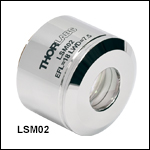
1250 to 1380 nm Wavelength Range
| Key Specificationsa,b | ||||
|---|---|---|---|---|
| Item # | LSM02 | LSM03 | LSM04 | LSM05 |
| Wavelength Range | 1250 to 1380 nm | |||
| Effective Focal Length | 18 mm | 36 mm | 54 mm | 110 mm |
| Lens Working Distance | 7.5 mm | 25.1 mm | 42.3 mm | 93.8 mm |
| Field of View, Maximum | 4.7 x 4.7 mm2 | 9.4 x 9.4 mm2 | 14.1 x 14.1 mm2 | 28.9 x 28.9 mm2 |
| Field of View, Diffraction Limited |
4.2 x 4.2 mm2 | 9.3 x 9.3 mm2 | 14.1 x 14.1 mm2 | 23.8 x 23.8 mm2 |
| Spot Size Plot, 1315 nm (Two-Axis Scan) |
|
 |
|
|
| Mounting Threads (External) | M25 x 0.75 | SM2 (2.035"-40) | ||
| Dispersion Compensator | LSM02DC | LSM03DC | LSM04DC | LSM05DC |
| Storage Casec | Lid: OC2M25 Canister: OC22 |
N/A | ||
- For detailed specs, please refer to the Specs tab.
- Click the blue icons, , to view the plots.
- Available for Purchase Separately
- Design Optimized for OCT Imaging Systems
- Entrance Pupil: 4 mm
- Scan Angle Range: ±10.6° (Maximum, Single Axis)
- Range of Effective Focal Length Options
- External M25 x 0.75 Mounting Threads
While these lenses are optimized for OCT imaging, they may also be used in a variety of laser scanning microscopy applications. The LSM02, LSM03, LSM04, and LSM05 scan lenses are designed and have AR coatings for imaging centered around 1315 nm in the near-infrared.
Representative plots of the spot size along the sagittal and tangential scan directions can be seen by clicking on the blue icons, ![]() , in the table to the right. For a detailed list of specifications, please see the Specs tab.
, in the table to the right. For a detailed list of specifications, please see the Specs tab.
The external M25 × 0.75 threading can be adapted to Thorlabs' standard SM1 (1.035"-40) threading by using an SM1A12 adapter. An RMSA2 adapter allows the scan lens to be used with RMS-threaded (0.800"-36) components.
For OCT imaging systems that utilize this scan lens as a primary objective element, we offer matched dispersion dispersion compensators for each scan lens; see the table to the right.
Part Number | Description | Price | Availability |
|---|---|---|---|
LSM02 | Scan Lens, 1250 to 1380 nm, EFL=18 mm | $1,834.15 | Lead Time |
LSM03 | Scan Lens, 1250 to 1380 nm, EFL=36 mm | $1,138.02 | Today |
LSM04 | Scan Lens, 1250 to 1380 nm, EFL=54 mm | $1,126.16 | 3 weeks |
LSM05 | Customer Inspired! Scan Lens, 1250 to 1380 nm, EFL=110 mm | $1,126.16 | Today |
Galvo Mirror and Scan Lens Mounting Bracket for LSM05

| Mounting Bracket Item # | GAS012 |
|---|---|
| Thread Adapter Item # | GAS0123 |
| Compatible Scan Lens | LSM05 |
| Compatible Galvo Mirror System | GVS012 or GVS012/M |
| Assembled System Photo (Click for Details) |
 |

- Mounting Bracket and Adapter for Integrating our LSM05 Telecentric Scan Lens with our GVS012(/M) Large Beam Galvo Mirror Pair
- GAS0123 Thread Adapter (Sold Below) Required for Attaching LSM05 Lens
- Removable 30 mm Cage- and SM1 Thread-Compatible Input Plate
- Compatible with Imperial or Metric Breadboards and Optical Tables
The GAS012 mounting bracket allows for the integration of our LSM05 Telecentric Scan Lens with our GVS012 or GVS012/M galvanometer mirror pairs. It also allows the complete assembly to be integrated with optical table or breadboard-based optomechanical setups. To use the GAS012 mounting bracket, the GAS0123 thread adapter (also sold below) must also be purchased. This places the lens at the recommended distance from the second galvo mirror.
The input light port is a plate with SM1 (1.035"-40) threading for Ø1" lens tube compatibility and four Ø6 mm cage rod holes for 30 mm cage system integration. The GAS012 bracket has a bottom mounting surface with eight #8 (M4) and nine 1/4" (M6) through holes, spaced at 12.6 mm (0.496") and 25.2 mm (0.99"), respectively, for compatibility with both imperial and metric breadboards and optical tables. When mounted, the GVS012(/M) galvo mirror pair does not sit directly on this surface, allowing all of the through holes to be used for table or breadboard mounting.
Part Number | Description | Price | Availability |
|---|---|---|---|
GAS012 | Customer Inspired! Scan Lens and Galvo Mirror System Mounting Bracket (Required Thread Adapter Sold Separately) | $188.88 | Today |
GAS0123 | Scan Lens Thread Adapter for GAS012 and LSM05 | $69.57 | Today |
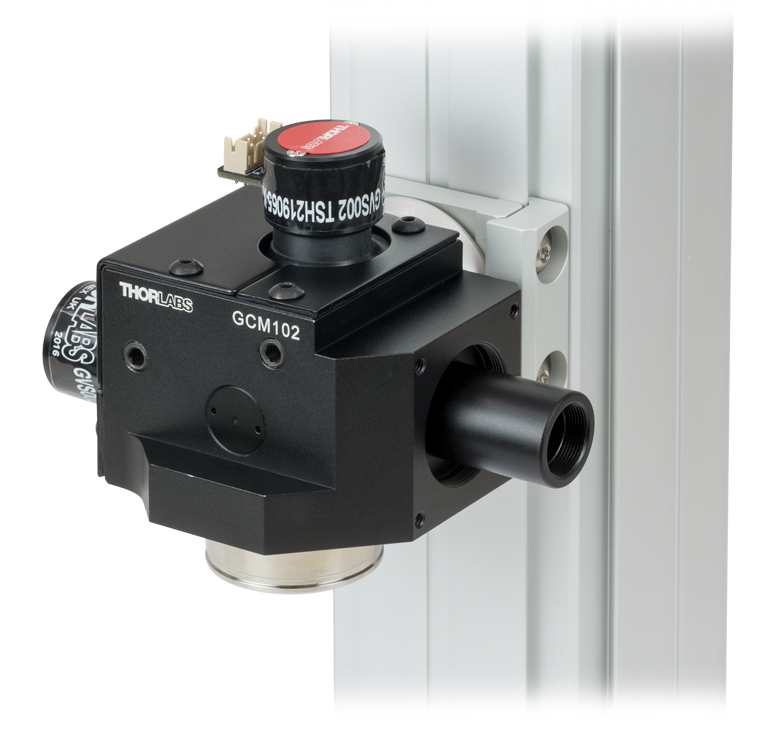
Mounting Adapter for Small Beam 2D Galvo Mirrors and Scan Lenses

Click for Details
GCM102(/M) Mechanical Drawing

Click to Enlarge
Beam Path Shown Through the Input Port, Reflecting off Both Galvo Mirrors, and then Exiting Through the SM2-Threaded Output Port
- Mount a 2D Galvo System to a Post, 30 mm Cage System, or 66 mm Rail Carriage
- Internal SM05 (0.535"-40) and SM1 (1.035"-40) Threads on Input Port
- Internal SM2 (2.035"-40) Threads on Output Port
- Compatible with Thorlabs' Selection of Scan Lenses (See Compatibility Table Below)
Thorlabs' GCM102(/M) is designed to securely mount any dual-axis, small beam diameter galvo mirror system. Once installed in the mount, the galvo system can be attached to a post, 30 mm cage system, or 66 mm optical rail carriage, as shown in the images below.
The mount features an internally SM2-threaded (2.035"-40) output port that, when used with the proper adapter, allows any of our scan lenses to be attached at the proper scan distance from the galvo mirrors; see the compatibility table below for more details. The input port is both internally SM05- (0.535"-40) and SM1-threaded (1.035"-40) for direct compatibility with Ø1/2" and Ø1" lens tubes. Additionally, four 4-40 tapped holes centered around the input port provide compatibility with 30 mm cage systems. When each port is used in combination with our lens tubes, port plugs, and/or scan lenses, the system will be light tight. The input and output ports are centered around the X- and Y-axis galvo mirrors, respectively; please note that they are in different planes.
The bottom of the mount includes two 1/4"-20 (M6), three 8-32 (M4), and two 4-40 (M3) tapped mounting holes. Each mounting hole is aligned for compatibility with our C1511 (C1511/M) and C1545 (C1545/M) post clamp adapters; Ø1/2", Ø1", and Ø1.5" mounting posts; and XT66P2 (XT66P2/M) and XT66RC rail carriages, as shown in the images below. Please see section 3.3 of the manual for more details about the various mounting options available.
The X- and Y-axis galvo mirrors are mounted using the two through holes in the side and rear of the unit. A flexure clamp that is actuated using the included 5/64" (3 mm) hex key secures each galvo mirror in place. An SM05-threaded viewing port is provided above the mirrors to assist in installation, while two 1/4"-20 (M6) through tapped holes provide access to each flexure clamp. The SM05 port and 1/4"-20 (M6) through tapped holes, which are located on the top of the GCM102, are blocked using an SM05PL plug or a 1/4"-20 (M6) setscrew, respectively, so that the system can remain light tight. For step-by-step instructions on how to install the galvo mirror, please see section 3.1 of the manual.


| Scan Lens Compatibilitya | |||
|---|---|---|---|
| Item # | Scanning Distanceb | Lens Mounting Thread | Required Adapterb |
| LSM02(-BB) | 16.1 mm ± 5 mm | External M25 x 0.75 | GCMA1 |
| LSM54-850 |
17.8 mm ± 7.5 mm | SM2A33 | |
| LSM54-1050 |
|||
| LSM54-1310 | |||
| LSM03(-BB) | 18.9 mm ± 5 mm | GCMA1c | |
| LSM04(-BB) | |||
| LSM03-VIS | 29.0 mm ± 5 mm | SM2A33 and SM2L03 | |
| SL50-CLS2 | 37.8 ± 4 mm | External SM30 (M30.5 x 0.5) |
SM2A11 and SM2V05 |
| SL50-2P2 | |||
| LSM05(-BB) | 75.5 mm ± 5 mm | External SM2 (2.035"-40) | SM2L20 |
| CLS-SL | 58 ± 6 mm | SM2L05 and SM2V05 | |
Part Number | Description | Price | Availability |
|---|---|---|---|
GCM102/M | Customer Inspired! Mounting Adapter for a 2D Galvo System, Metric | $277.23 | 3 weeks |
GCM102 | Customer Inspired! Mounting Adapter for a 2D Galvo System, Imperial | $277.23 | Today |
Thread Adapter for SL50-CLS2, SL50-2P2, or SL50-3P Scan Lenses
- Internal SM30 (M30.5 x 0.5) Threads for Mounting SL50 Scan Lenses
- External SM1 (1.035"-40) Threads for Compatibility with Galvo-Galvo and Galvo-Resonant Scan Heads
The SM1A70 adapter allows the SL50-CLS2, SL50-2P2, or SL50-3P scan lens to be secured to the output port of an LSKGGR(/M), LSK-GR08(/M), or LSK-GR12(/M) scan head at the correct distance from the scan mirrors. The adapter features internal SM30 (M30.5 x 0.5) threads as well as external SM1 (1.035"-40) threads.
Part Number | Description | Price | Availability |
|---|---|---|---|
SM1A70 | Adapter with External SM1 Threads and Internal SM30 Threads, 0.47" Long | $29.99 | Today |