OCT Collimators

- Collimation/Coupling Package with Aspheric Lens Element
- Diffraction-Limited Performance at 1310 nm
- Broadband AR Coating: 1050-1600 nm
F280APC-C
F260APC-C
OVERVIEW
| Specifications | F260APC-C | F280APC-C |
|---|---|---|
| 1/e2 Beam Diameter | 2.74 mm | 3.27 mm |
| Theoretical Full Angle Beam Divergence | 0.035° | 0.029° |
| NA of Aspheric Lens Element | 0.16 | 0.15 |
| Distance of Beam Waist from the Front of the Collimation Package | 14.8 mm | 18.0 mm |
| AR Coating Range | 1050-1600 nm | |
| Design Wavelength | 1310 nm | |
| Fiber Used for Alignment | SMF-28e | |
| Mode Field Diameter of Fiber at Design Wavelength | 9.2 ± 0.4 µm | |
Features
- AR Coated Aspheric Lens: 1050 -1600 nm
- Diffraction Limited Collimation
- Compatible with FC/APC Fiber Connectors
- Ideal for Use with LSM Scan (Objective) Lenses
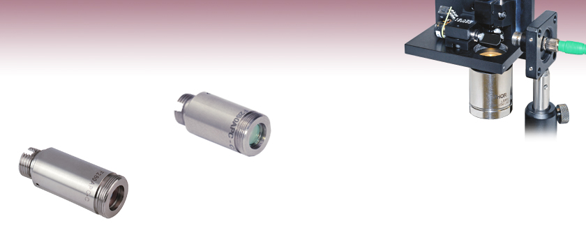
The F260APC-C and F280APC-C fiber collimation packages are pre-aligned at the factory to collimate a laser beam propagating from the tip of an FC/APC connectorized fiber with diffraction-limited performance at the design wavelength of 1310 nm. The FC/APC connectorized collimation packages are ideal for systems that are sensitive to back reflections since APC-Style connectors utilize a ferrule that has an 8° end face, and in conjunction with an ultra PC polish, provides a return loss greater then 60 dB. The factory alignment positions the aspheric lens so that the distance between it and the fiber tip inserted into the collimator is equal to the focal length of the aspheric lens at the design wavelength. Since the F200 Series of fiber collimators do not have any movable parts, they are compact and not susceptible to misalignment. Although this type of collimator is generally used in applications using a monochromatic 1310 nm light source, additional design and testing was performed to ensure the suitability of the collimator for use in OCT applications. For more information, see the OCT Application tab. The aspheric lens has an AR coating that minimizes the reflections at the surfaces of the aspheric lens. These packages can also be used to couple a free-space laser beam into an optical fiber; in such cases, please note that the NA of the patch cable needs to be greater than or equal to the NA of the collimator and the diameter of the focused laser beam needs to be smaller than the MFD of the fiber to obtain a high coupling efficiency when properly aligned. Please call our technical support group if you would like assistance with this application. For the F260APC and F280APC collimation packages, the suggested mounting adapter is the AD11F.
We also offer a line of adjustable collimation packages called FiberPorts that are well suited for a wide range of wavelengths and is also an ideal solution for an adjustable, compact fiber coupler. For other collimation and coupling options, please click here.
OCT APPLICATION
OCT compatible components are components that have gone through additional steps in the design and product testing phase in order to verify their suitability for use in OCT imaging systems. The F260APC-C and F280APC-C are two collimation / coupling packages that are ideal for use in an OCT scan head. Specifically, the F280APC-C collimator when paired with any of the LSM scan objectives using the SL1325-P16 as a light source can be used to produce a high-performance OCT scan head. The collimator is designed for FC/APC connectorized patch cords, which minimize back reflections that degrade the image produced by the OCT imaging system. The LSM scan lenses are designed to create a uniform spot size and optical path length for the laser for every scan position, which allows a uniform, high-quality, image of the sample to be formed. In addition, the design of the scan lenses and the lens coatings used were chosen to minimize back reflections, which can severely degrade the OCT image quality.

OCT Scan Head
The schematic to the right shows the basic design of a scanning head for an Optical Coherence Tomography (OCT) Imaging System. The F260APC-C and F280APC-C have been extensively tested and modeled to determine their performance characteristics when placed in a systems like this. Below are the results for the beam divergence of the collimator, spot size produced by the scan head using and LSM03 scan lens, and the coupling efficiency. The collimator should be positioned so that the beam waist is coincident with the entrance pupil of the scan lens. The beam waist / entrance pupil should also be coincident with the center of the reflective face of the 2D steering mirror (galvo mirror). For systems using two 1D galvo mirrors, the beam waist / entrance pupil should be located between the two mirrors in order to minimize any optical path length differences in the system.
The beam waist with respect to the end of the collimator housing:
- F260APC-C: 14.8 mm
- F280APC-C: 18.0 mm
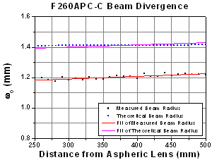
The plot above shows the beam waist data used to determine the theoretical and measured beam divergence of the F260APC-C OCT collimator when used with a 1310 nm source. The fits yield a measured beam waist of 1.13718 mm and a theoretical beam waist of 1.35548 mm. The calculated full angle beam divergence using the measured and theoretical beam waist fits are 0.042° and 0.035°, respectively.
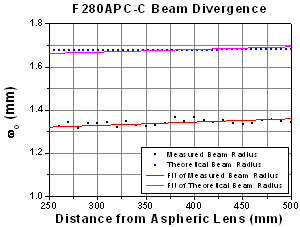
The plot above shows the beam waist data used to determine the theoretical and measured beam divergence of the F280APC-C OCT collimator when used with a 1310 nm source. The fits yield a measured beam waist of 1.28102 mm and a theoretical beam waist of 1.63133 mm. The calculated full angle beam divergence using the measured and theoretical beam waist fits are 0.037° and 0.029°, respectively.
The theoretical data was generated using Zemax while the measurement was done using a previous generation of Thorlabs' complete M² IR beam analysis system (information on our current generation of M² beam analysis system can be found here). The M² analysis system can measure the times-diffraction-limit M² factor of a laser beam, its reciprocal beam quality (K=1/M²) in addition to the divergence, waist diameter, Rayleigh range, and astigmatism of the beam.
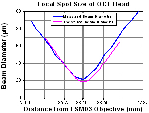
The plot above shows the data used to determine the theoretical and measured focal spot size of an OCT Scan Head. The OCT scan head used (modeled) to generate this data consisted of a fiber coupled 1310 nm source, an F260APC-C OCT Collimator, and an LSM03 Scan Lens. The component arrangement can be seen in the schematic above.
The plot above shows the data used to determine the theoretical and measured focal spot size of an OCT Scan Head. The OCT scan head used (modeled) to generate this data consisted of a fiber coupled 1310 nm source, an F280APC-C OCT Collimator, and an LSM03 Scan Lens. The component arrangement can be seen in the schematic above.
The theoretical data was generated using Zemax while the measurement was done using a previous generation of Thorlabs' complete M² IR beam analysis system (information on the current version, the M2SET-BP209IR, can be found here). The M² analysis system can measure the times-diffraction-limit M² factor of a laser beam, its reciprocal beam quality (K=1/M²) in addition to the divergence, waist diameter, Rayleigh range, and astigmatism of the beam.
The plot above shows the data used to determine the theoretical and measured coupling efficiency of the F260APC-C OCT collimator when used with an LSM03 Scan Lens.
The plot above shows the data used to determine the theoretical and measured coupling efficiency of the F280APC-C OCT collimator when used with an LSM03 Scan Lens.
The coupling efficiency is the percentage of light collected and collimated by the LSM03 scan lens that is coupled into an SMF-28e single mode fiber using the OCT collimator indicated in the caption below each plot.
Part Number | Description | Price | Availability |
|---|---|---|---|
F260APC-C | 1310 nm, f = 15.52 mm, NA = 0.16, FC/APC Fiber Collimation Pkg. | $245.26 | 3-5 Days |
F280APC-C | 1310 nm, f = 18.67 mm, NA = 0.15, FC/APC Fiber Collimation Pkg. | $245.26 | 3-5 Days |


.jpg)
.jpg)