Waveguide Mounts
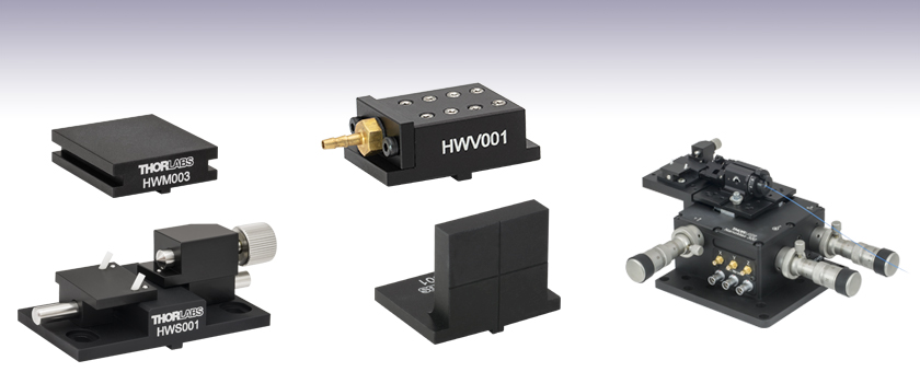
- Vacuum Waveguide Mounts
- Adjustable Waveguide Mounts
- Blank for Custom Mounts
HWM003
HWS001
HWV001
HBB001
HWS001
Application Idea

Please Wait
The mounts on this page are specialized for waveguide applications. Thorlabs offers a wide variety of flexure platform mounts that utilize the alignment keyway found on our multi-axis flexure platforms.
Flexure stage mounts can be fixed in position using AMA010(/M) mounting cleats, which are sold below. Each cleat is designed with one edge milled flat, making it possible to insert or remove a flexure stage mount without removing the clamp. Simply loosen the clamp screw and rotate the flat side of the lock-down clamp inward to release the flexure stage mount.
| Multi-Axis Stage Accessories | |||||||||||
|---|---|---|---|---|---|---|---|---|---|---|---|
 |
 |
 |
 |
 |
 |
 |
 |
 |
 |
 |
 |
| Fiber Mounts |
Fiber Rotators |
Waveguide Mounts |
Diode Mounts |
Fixed Mounts |
Kinematic Mounts |
Top Plates |
Extension Platforms |
Fiber Chucks |
Slide Holders |
Kinematic Platforms |
Adapter Plates |
| Posted Comments: | |
Jan FitzGibbon
(posted 2024-03-05 09:26:08.91) The Autocad PDF dimensions are false, the diameter of the nozzle is not 2.5mm, it is 2mm. This is an important measurement for the vacuum when selecting tubing. do'neill
(posted 2024-03-15 06:48:20.0) Thank you for your feedback, I will look into this to see if the drawings need clarifying or correcting. These are designed for tubes with an inner diameter of 2mm. I will reach out to you to further discuss your application. Chris Axline
(posted 2023-04-26 10:02:27.573) The acceptable chip width is 4-38 mm, but the specifications do not say anything about minimum chip length. The minimum length appears to be 15 mm (is this correct?). It would be helpful if this were clearer. scott.hendrickson
(posted 2013-06-27 15:11:57.457) Could you please comment on the type of vacuum pump you recommend using with the vacuum waveguide holder? cdaly
(posted 2013-07-03 13:23:00.0) Response from Chris at Thorlabs: Thank you for using our feedback tool. The suitability of a vacuum is highly dependent on how flush the waveguide is to the mounting surface, the shape of the waveguide, whether the mount is orientated upside down, weight of the waveguide etc. giving a very large scope for what level of vacuum is suitable for the application. We would state however that a high vacuum is not required. As this is made from anodised aluminium, a really high vacuum may cause some issues with their pumping equipment if the vacuum is too strong. The vacuum should implement 2mm ID tubing in order to interface with the HWV001. |

- Eight User-Selectable Vacuum Ports Provide Support for a Broad Range of Optic Sizes
- Small, Compact Design Allows Easy Access to your Planar Optical Element
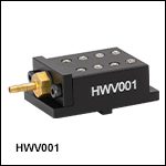
The HWV001 waveguide holder utilizes a vacuum to provide the holding force when securing planar waveguide devices. The mount consists of a platform, into which a series of connected holes are provided. A series of conical-tipped setscrews (compatible with a 1.5 mm hex key) are included to block the unused ports. By removing just the setscrews that will lie underneath the optical element, a vacuum-generated holding force, appropriate for the size of the component, will be available. The vacuum connection is designed for tubing with a 1/16" inner diameter or the closest metric equivalent. The strength of vacuum required is dependent on the specific application; however a high vacuum should not be used as the anodization of the mount may negatively impact the pumping equipment.

- Accepts Thin Rectangular Elements 4 - 38 mm Wide and <2 mm Thick
- 3-Point Contact via Precision-Ground Chromium Steel Balls
- Adjustable Holding Force Provided by a Beveled Spring-Loaded Plunger
The HWS001 adjustable waveguide mount, while originally intended for use with planar waveguides, is useful for mounting a broad range of optical devices. Any thin (<2 mm thick) rectangular device requiring integration into an optical system utilizing a Thorlabs' multi-axis flexure stage can be mounted in this holder, provided the width of the device is less than 38 mm. This broad range of sizes is supported by moving the two sliding platforms to within a few millimeters of the width of the device and then locking them into position with the setscrews. The holding force is supplied by a spring-loaded plunger that pushes the optical element against two, angled, white plastic pegs. A kinematic three-point contact is also achieved using three hardened chromium steel balls as optical support points.
Note. The HWS001 is not compatible with the MBT401 4-axis Device Platform

- 10 mm and 35 mm Lengths
- Please Call Tech Support for a Quote to Customize One of These Mounts
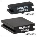
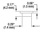
Our standard waveguide mounts are used to mount customer-supplied waveguide devices. All waveguide mounts are supplied with a tongue that fits snugly into the locating slots of the nanopositioner platforms or brackets. Users can glue experimental devices directly to the waveguide mounts. All mounts are 9.5 mm high, with 3 mm clearance to the nominal optical axis, and 32 mm wide. All of the plain waveguide mounts are designed to accommodate different sized devices while allowing access for single mode fibers or microscope objectives.

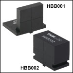
While we offer an extensive line of fiber launch and waveguide accessories, it is difficult to anticipate all of the possible requirements that may arise for customers. Hence, we have added these simple components, which ease the production of one-of-a-kind mounting accessories. As can be seen in the photograph to the left, the front surface of each blank is clearly marked with witness lines, which are centered on the 12.5 mm high optical axis of our multi-axis flexure systems.

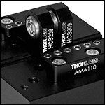
Click for Details
Accessories mounted in close proximity using the AMA110 Mounting Block.
- Secures Components to NanoMax, MicroBlock, or RollerBlock Stages
- Cleats for Mounting Single Components
- Mounting Blocks and Clamps for Close Proximity Mounting of Multiple Components
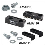
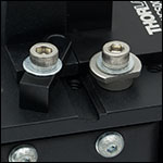
The AMA010(/M) Cleats have a flat milled along one side. To lock an accessory along the center alignment groove, rotate the cleat so that the flat is facing the groove. Place the accessory into the groove between the cleats, rotate the cleat so that the rounded edge covers the edge of the mount, and lock down the 6-32 (M3) locking screw and washer. The cleats can be rotated without needing to remove the locking screws. See the animation to the right for details. The included screws are 5/16" (8 mm) long and are used with a 3/32" (2.5 mm) hex key.
For mounting multiple components in close proximity, we offer the AMA110 mounting blocks. These mounting blocks feature a line of nylon-tipped setscrews to secure components, and allow for easy repositioning and very close mounting. The blocks are secured via two holes and are supplied with either 6-32 or M3 cap screws.
The AMA111 Narrow Device Mounting Clamps offer an alternative solution when devices need to be mounted close together. They are secured using an M3.5 or M3 washer and a 6-32 or M3 cap screw, compatible with a 7/64" or 2.5 mm hex key, respectively.
 Products Home


 Zoom
Zoom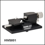


 Waveguide Mounts