Dispersion Measurement System
- Rapidly Characterize Dispersion in Optical Components
- Broadband Spectral Range: 500 - 1650 nm
- GDD Measurement Accuracy: ±5 fs2
- Reflection and Transmission Modes
Chromatis™ Dispersion Measurement System
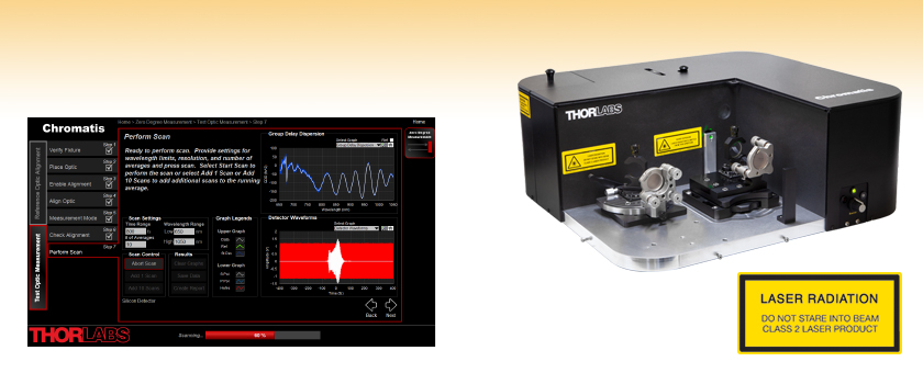
Software Screen Showing a Detected Interferogram and Calculated Dispersion

Please Wait
Click to Enlarge
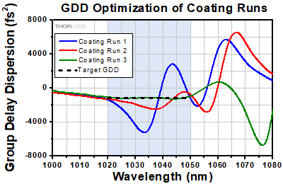
Figure 1.1 Example customer data taken with the Chromatis™ dispersion measurement system to aid in optimizing an optical coating. The targeted GDD (black dashed line) for this 1030 nm mirror is -1200 fs2 over the 1020 nm to 1050 nm wavelength range (blue shaded area). The first two runs show significant error in the GDD.
Click to Enlarge
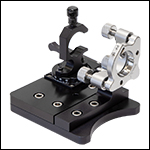
Figure 1.3 Zero-Degree Reflection and Transmission Fixture
Click to Enlarge
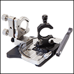
Figure 1.2 Angled Reflection Fixture
Click to Enlarge
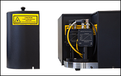
Figure 1.4 The Detector Housing Area (Cover Removed)
Features
- Fiber-Coupled, Stabilized Halogen Light Source with Broadband Emission
- Accepts Ø1/2" (with AD1 Adapter) and Ø1" Optics
- Three Standard Measurement Modes with Included Fixtures and Reference Optics:
- 0° Reflection
- 0° - 70° Transmission
- 5° - 70° Angled Reflection
- Two User-Replaceable Detector Modules Available:
- Si: 500 - 1100 nm (Included)
- InGaAs: 1000 - 1650 nm (Item # CHRDETN Available Separately)
- Measures S- and P-Polarization Simultaneously
- Includes HeNe Reference Laser for Wavelength Self-Calibration
- Includes Red and Green Diode Lasers for Spatial Alignment
- Electronics Contained in Rack-Mountable 2U Enclosure (3.5" Panel Height)
- Operated by Included Windows Laptop with Pre-Installed Software
- Contact Us to Discuss Fixtures for Non-Standard Optic Sizes or Mirror Pairs
Applications
- Quality Control and Inspection on Coating Group Delay or Group Delay Dispersion Specifications
- Refining Dispersion-Controlled Coating Design for Low Deviation from Desired Specification
- Matching Chirped Mirrors for Best Ripple Cancellation
- Measurement-Based Dispersion Modeling of Ultrafast Oscillator Cavities
- Dispersion Coating Design Research and Development
Thorlabs' Chromatis™ Dispersion Measurement System is a free-standing instrument designed to rapidly characterize the dispersion properties of optics and optical coatings with an accuracy of ±5 fs2. Featuring a fiber-coupled, stabilized halogen light source, the broadband measurement bandwidth of this system is ideal for measuring the properties of ultrafast optics that are used with femtosecond pulsed lasers, such as Ti:sapphire, ytterbium fiber, and erbium fiber lasers. The following properties are characterized during each measurement: phase, group delay, group delay dispersion (GDD), third order dispersion, and fourth order dispersion.
Operation
Ultrafast pulses broaden as they propagate through an optical system; short pulse widths can be recovered by knowing the GDD induced by each optic and compensating for the distortions appropriately. For highly accurate and reliable results, the Chromatis uses time-domain white light interferometry (WLI) to measure the GDD; see the Operation tab for more details. The Chromatis optical head includes several filters for restricting the range of wavelengths under analysis, which can be beneficial in cases of optics with broadband dispersion properties or high dispersion. The included filters cover the ranges of 500 - 700 nm, 600 - 1000 nm, and 950 - 1100 nm when used with the Si detector module.
To overcome the challenges of aligning an interferometer with an incoherent light source, the Chromatis system includes red and green alignment lasers. The interference fringes for these coherent sources are visible over the full range of the motor, allowing the spatial overlap to be optimized at any position. Users can select which source reflects best off the test optic using the knob on the front panel of the optical head (see the Panels tab). Also included in the system is a HeNe reference laser, which co-propagates with a vertical offset to the white light to calibrate the wavelength axis.
Two precision fixtures are included with the Chromatis system to accommodate three standard measurement modes: zero-degree reflection, transmission, and angled reflection. Each precision fixture is designed to hold Ø1" optics and an AD1 adapter is included for compatibility with Ø1/2" optics; see the Fixtures tab for details. Reference optics are also included to verify the system operation for each fixture. To test optics with non-standard shapes and sizes, please contact us.
A power supply unit is included with the Chromatis dispersion measurement system, which is designed for use with a standard 19" equipment rack (mounting screws are not included). For a detailed list of items shipped with the Chromatis system, please see the Shipping List tab.
Detector Modules
The Chromatis system detects s- and p-polarized white light interference signals using a Si detector module, which includes two gain-adjustable Si photodiodes that cover the 500 nm to 1100 nm range. For measurements extending further into the NIR, the CHRDETN InGaAs detector module that operates from 1000 nm to 1650 nm is available for purchase separately. To characterize an optic over the full 500 nm to 1650 nm wavelength range, measurements must be taken separately with each detector module. The Si and InGaAs detectors cannot be connected at the same time, so the modules must be switched out and the individual measurements stitched together to cover the full range.
The Chromatis optical head features a detector housing area, which can be easily accessed via two 2.5 mm hex cap screws. Each detector module features two precision pins for alignment and is mounted to the optical head base plate with an M6 cap screw (5 mm hex). Hex keys are not included.
Please note that the Chromatis system is factory-calibrated to remove any residual dispersion from the fixed system optics. When the CHRDETN InGaAs detector module is purchased together with the Chromatis, the system is calibrated for both Si and InGaAs detectors. Please contact Tech Support if the CHRDETN InGaAs detector module is purchased separately.
Software Interface
This dispersion measurement system includes user-friendly software that guides the user through beam alignment (fringe optimization), automatically finds the zero-time delay position (position where light fringes occur), and measures the dispersion of a typical optic in minutes. For measurements over a broad spectral range, the Chromatis software is also compatible with both the Si and InGaAs detector modules. See the Software tab for additional details.
Note: The Chromatis software has options for four measurement types: zero-degree, transmission, angle, and mirror pair. However, the fixture required for the mirror pair measurement is not included with the Chromatis dispersion measurement system. To purchase the mirror-pair precision fixture, contact us.
Click to Enlarge
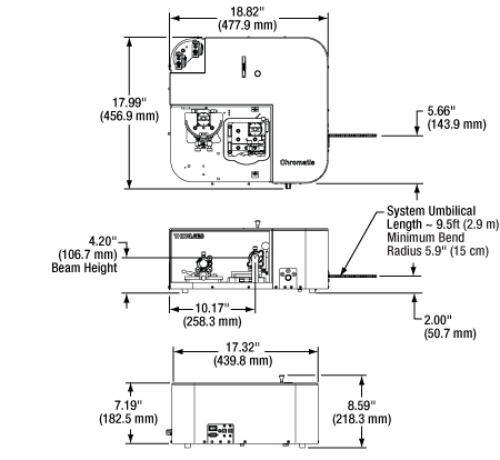
Figure 2.1 Mechanical Dimensions of the Chromatis Optical Head
| System Specifications | |||
|---|---|---|---|
| Group Delay Dispersion (GDD) Accuracya | ± 5 fs2 | ||
| Polarization | S- and P-Polarization Measured Simultaneously | ||
| Accepted Optic Diameterb | Ø1/2", Ø1" | ||
| White Light Source Wavelength Range | 500 - 2100 nm | ||
| Detector Wavelength Range | Si | 500 - 1100 nm | |
| InGaAsc,d | 1000 - 1650 nm | ||
| Optical Head Dimensions (L x W x H) | 18.82" x 17.99" x 8.59" (477.9 mm x 456.9 mm x 218.3 mm) |
||
| Precision Fixture Specifications | |||
|---|---|---|---|
| Fixture | Measurement Mode | Accepted Angle of Incidence (AOI) | Reference Optic |
| Zero Degree and Transmissiona | Zero Degree Reflection | 0° | Bare Gold Mirror |
| Transmission | 0° - 70° | 3 mm Fused Silicab | |
| Angle of Incidence Reflectiona | Angled Reflection | 5° - 70° | Bare Gold Mirrorc |
| Laser Output Specifications | |||
|---|---|---|---|
| Light Source | Green Alignment | Red Alignment | Reference |
| Wavelength | 523 nm | 635 nm | 632.8 nm |
| Beam Size (Diameter), Divergence | Ø6 mm, Collimated | Ø6 mm, Collimated | Ø2 mm, Collimated |
| Power Output | <0.1 mW (CW) | <0.1 mW (CW) | <0.8 mW (CW) |
Click to Enlarge
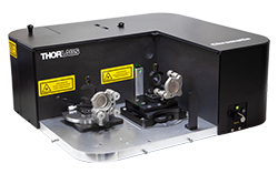
Figure 3.2 The Chromatis optical head set up for a transmission measurement.
Click to Enlarge
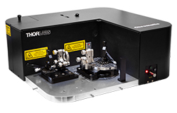
Figure 3.1 The Chromatis optical head set up for an angled reflection measurement.
Precision Fixtures
Designed to enable easy and fast measurements of mirrors and transmissive optics, two precision fixtures are provided to carry out three different measurement modes: zero-degree reflection, transmission, and angled reflection. Each precision fixture can accept Ø1" optics, as well as Ø1/2" optics when used with the provided AD1 adapter. For fixtures that facilitate measurements on a mirror pair or non-standard optics sizes, please contact us.
To eliminate the need for additional tools, the precision fixtures are locked into place or removed via a locking wheel. When not in use, the fixtures should be mounted on the baseplate in the dedicated storage area, as shown in Figures 3.1 and 3.2.
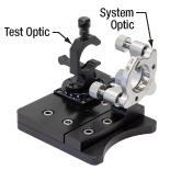
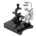
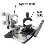
Each precision fixture has a location for mounting the test optic, which is the user-supplied optic or the reference optic. The black anodized mounts, which hold the test optic in angled reflection and transmission measurements, feature a tightening thumbscrew with a spring-mounted nylon tip for safe and easy optic mounting. For zero-degree reflection measurements, the previous-generation
Click to Enlarge
Figure 3.3 Precision Fixture for Transmissive Optics at 0° to 70° Angle of Incidence
| Precision Fixture Specifications | |||
|---|---|---|---|
| Fixture | Measurement Mode | Accepted Angle of Incidence (AOI) | Reference Optic |
| Zero Degree and Transmissiona | Zero Degree Reflection | 0° | Bare Gold Mirror |
| Transmission | 0° - 70° | 3 mm Fused Silicab | |
| Angle of Incidence Reflectiona | Angled Reflection | 5° - 70° | Bare Gold Mirrorc |
Click to Enlarge
Figure 3.4 Precision Fixture for Reflective Optics at 0° Angle of Incidence
Click to Enlarge
Figure 3.5 Precision Fixture for Reflective Optics at 5° to 70° Angle of Incidence
Click to Enlarge
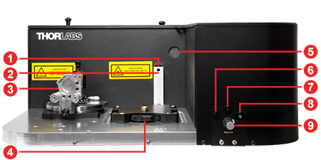
Figure 4.1 Chromatis Optical Head Front Panel
Click to Enlarge
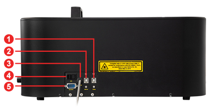
Figure 4.2 Chromatis Optical Head Side Panel
| Front Panel | |
|---|---|
| Callout | Description |
| 1 | White Light Source and Alignment Laser Output |
| 2 | HeNe Reference Laser Output |
| 3 | Fixture Installation Area (Storage) |
| 4 | Fixture Installation Area (Measurement) |
| 5 | Alignment Viewing Screen |
| 6 | LED Indicator Light for Red Alignment Laser |
| 7 | LED Indicator Light for Green Alignment Laser |
| 8 | LED Indicator for White Light Source |
| 9 | Light Selection Switch |
| Back Panel | |
|---|---|
| Callout | Description |
| 1 | USB 2.0 Type-B Connector |
| 2 | USB 2.0 Type-B Connector |
| 3 | Fiber Optic Cable for Light Sources (Not Removable) |
| 4 | On/Standby Switch |
| 5 | 15-Pin Male D-Sub Connector |
Click to Enlarge
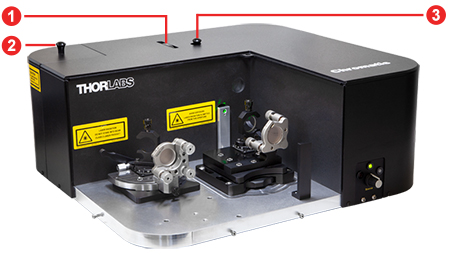
Figure 4.3 Chromatis Optical Head Top Panel
| Top Panel | |
|---|---|
| Callout | Description |
| 1 | Filter Selection Wheel |
| 2 | Detector Module Cover |
| 3 | Alignment Knob |

Click to Enlarge
Figure 4.4 Chromatis Power Supply Back Panel
| Back Panel | |
|---|---|
| Callout | Description |
| 1 | On/Off Power Switch |
| 2 | AC Power Input |
| 3 | Light Source Output Port (SMA Connector) |
| 4 | 15-Female D-Sub Connector |
Click to Enlarge
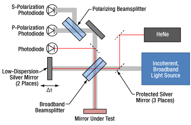
Figure 5.1 A schematic of the white light interferometer and optical paths inside the Chromatis optical head. The beam paths for the HeNe reference laser and white light source are vertically offset by a few millimeters.
Click to Enlarge
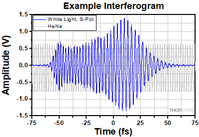
Figure 5.2 Example interferogram from measuring a chirped mirror at zero degrees with the Chromatis system (blue line). The asymmetry of the interferogram indicates that the blue wavelengths are arriving before the red wavelengths. Also included is the HeNe laser (gray line), which is used as a distance reference.
White Light Interferometery
The Chromatis™ dispersion measurement system includes a fiber-coupled incoherent broadband light source that is collimated and then sent through an interferometer that consists of a broadband, low dispersion beamsplitter, and two delay arms. The arm with the test mirror, which is mounted in a precision fixture, has a fixed length, and the other, containing the low-dispersion reference optic, has variable length to introduce the time delay (Δt).
To measure the white light interference fringes, the time delay between the two arms is scanned across the zero-time delay
(Δt = 0). In the regions around Δt = 0, an interference pattern can be detected by a photodiode and recorded by the Chromatis software. Two Si detectors are included to facilitate both s- and p-polarized measurements; the CHRDETN InGaAs detector module is available separately. To serve as a distance reference for the time delay scan (i.e., wavelength axis calibration), a HeNe laser is co-propagated with a vertical offset to the white light, and the resulting interference fringes are recorded on a separate photodiode.
The white light interference pattern contains information about the relative phases of the light from the test arm and the reference arm. The Chromatis software processes the interference pattern and extracts the phase and dispersion properties of the mirror under test. This system can also can measure the dispersion of a transmissive sample by replacing the test mirror with a low- dispersion mirror and placing the transmissive sample in the beam path.
The Chromatis dispersion measurement system directly measures the phase φ of the optic under test and converts the phase to dispersion through numerical derivatives.1 The group delay and dispersion properties are defined as:


where ω is the angular frequency. The wavelength λ and the speed of light c are related to ω through the following relation:

- More in-depth information can be found in: S. Diddams and J. Diels, "Dispersion measurements with white-light interferometry," J. Opt. Soc. Am. B 13, 1120-1129 (1996).
The user-friendly software included with the Chromatis™ dispersion measurement system is designed to guide users of any experience level through the entire measurement process. Step-by-step alignment procedures with detailed on-screen instructions are provided for measurements on either reference or test optics. The software then automatically finds the zero-delay position, as well as records the interference pattern and determines the dispersion. In the case of an advanced user, the step-by-step instructions can be switched off. Several screenshots of the software carrying out a measurement are shown below.
For each run, the data can be saved as a .CSV file, and saved alongside is a .TXT file containing any user-specified notes and the scan settings. Also available is a report generation feature, which allows the user to select six graphs to display that can be printed or saved as a .JPEG file.
The Chromatis dispersion measurement system ships with a laptop that has the Chromatis software pre-installed. However, should the software need to be installed on a different computer or reinstalled on the provided laptop, please contact Tech Sales.
Note: The fixture required for the mirror pair measurement is not included with the Chromatis dispersion measurement system. For more information, please contact us.
Click to Enlarge
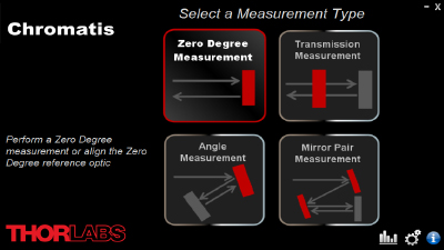
Figure 6.1 The home screen of the Chromatis software shows the four measurement types available for selection. The fixture required for the mirror pair measurement is not included with the Chromatis dispersion measurement system; contact us for more information.
Click to Enlarge
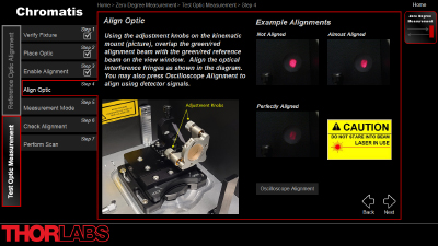
Figure 6.2 The Align Optic screen features animations that show fringes resulting from misalignment, near-alignment, and alignment. The image to the left shows which adjustment knobs should be used for alignment. For users who prefer to align the system with detector signals, "Oscilloscope Alignment" can be selected.
Click to Enlarge
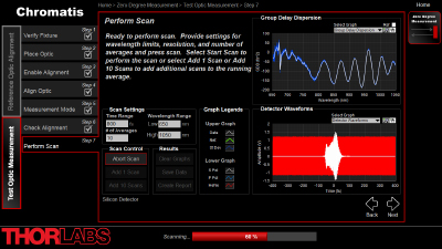
Figure 6.3 In the Perform Scan screen, the user can set the scan settings, which include: the wavelength range of interest, the time range of interest, and number of averages. As the Chromatis system records the data, the Group Delay Dispersion (GDD) graph is updated in real time with the average result (white line) and the standard deviation of the measurements (blue-filled area). After the scan is complete, the graph display can display the following: phase, group delay, GDD, third-order dispersion, or fourth-order dispersion.
Click to Enlarge
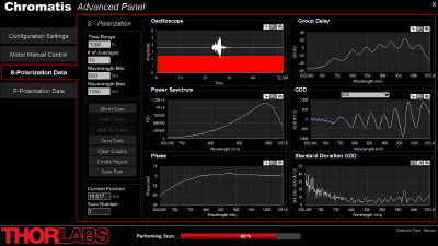
Figure 6.4 To make measurements without guided instructions, advanced users can work within the Advanced Panel. This panel has four tabs: configuration settings, motor control, s-polarization, and p-polarization. These allow users to manually set hardware and software parameters, watch the photodiode signals while manually moving the motor, and display s- or p-polarized data, respectively.
Click to Enlarge
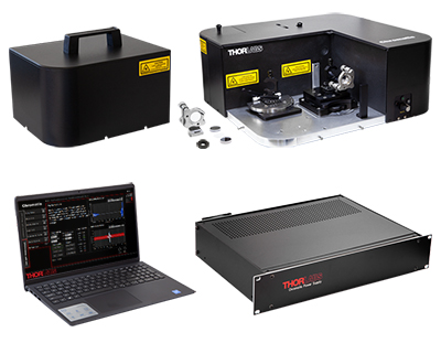
Figure 7.1 CHROMATIS Contents (Cables and Torx Key Not Shown)
The Chromatis™ Dispersion Measurement System contains the following components:
- Chromatis Optical Head (Armored Fiber Cable is Permanently Attached)
- Dust Cover for Optical Head
- Chromatis Power Supply Unit
- 0° Reflection and Transmission Precision Fixture
- Angle of Incidence Reflection Precision Fixture*
- Calibrated System Optic for Transmission Measurements
- Calibrated Reference Optics (Qty. 2)
- AD1 Ø1" OD Adapter for Ø1/2" Optic, 0.25" Thick
- Laptop with Pre-Installed Software
- USB 2.0 Type-A to Type-B Cable, 10' (3.05 m) Length (Qty. 2)
- 15-Pin D-Sub Cable, Female to Male, 10' (3.05 m) Length
- Region-Specific AC Power Cord
- Torx T10 Key for White Light Bulb Replacement
*The sliding portion of the angle of incidence reflection fixture, which includes the previous-generation POLARIS-K1 mirror mount with the mounted calibrated system optic, is packaged separately from the fixture.
| Posted Comments: | |
SANG BONG LEE
(posted 2020-02-25 18:56:21.773) hellow
I want chromatis & acceaccessoris quote. llamb
(posted 2020-02-26 01:25:43.0) Thank you for your interest in Thorlabs products. We will reach out to you directly for this quote and to discuss your application. For future reference, you may reach out to Applications@thorlabs.com directly for more information on our Dispersion Measurement System. |
Thorlabs offers a wide selection of optics optimized for use with femtosecond and picosecond laser pulses. Please see below for more information.
| Low-GDD Mirrors | |||||
|---|---|---|---|---|---|
 |
 |
 |
 |
 |
 |
| 355 - 445 nm | 460 - 590 nm | 700 - 930 nm | 970 - 1150 nm | 1400 - 1700 nm | 1760 - 2250 nm |
| Dielectric Mirror | High-Power Mirrors for Picosecond Lasers |
Metallic Mirrors | Low-GDD Pump-Through Mirrors |
||
|---|---|---|---|---|---|
 |
 |
 |
 |
 |
 |
| Dual-Band Dielectric Mirror, 400 nm and 800 nm |
Ytterbium Laser Line Mirrors, 250 nm - 1080 nm |
Ultrafast-Enhanced Silver Mirrors, 750 - 1000 nm |
Protected Silver Mirrors, 450 nm - 20 µm |
Unprotected Gold Mirrors, 800 nm - 20 µm |
Pump-Through Mirrors, 1030 - 1080 nm and 940 - 980 nm |
| Deterministic GDD Beamsplitters |
Low-GDD Harmonic Beamsplitters |
Low-GDD Polarizing Beamsplitters |
β-BBO Crystals | Dispersion-Compensating Optics | |
|---|---|---|---|---|---|
 |
 |
 |
 |
 |
 |
| Beamsplitters & Windows, 600 - 1500 nm or 1000 - 2000 nm |
Harmonic Beamsplitters, 400 nm and 800 nm or 500 nm and 1000 nm |
High-Power, Broadband, High Extinction Ratio Polarizers, 700 - 1300 nm |
β-BBO Crystals for Second Harmonic Generation |
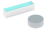
Dispersion-Compensating Mirrors, 650 - 1050 nm |
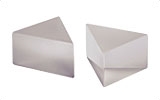
Dispersion-Compensating Prisms, 700 - 900 nm |
 Products Home


 Dispersion Measurement System