 Products Home / Optomechanical Components / Vacuum Components / Vacuum-Compatible Fiber Components / Vacuum-Compatible Terminated Fiber Adapters
Vacuum-Compatible Terminated Fiber Adapters

- FC/PC and SMA Fiber Connector Adapters
- External SM1 (1.035"-40) Threads
- Shipped Double Vacuum Bagged
- Vacuum-Compatible to >10-10 Torr
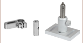
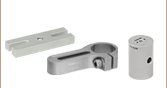
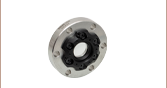
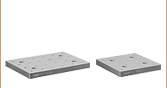
SM1FCV
Vacuum-Compatible
FC/PC Fiber Adapter Plate
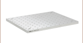
SM1SMAV
Vacuum-Compatible
SMA Fiber Adapter Plate
Application Idea
SM1SMAV Fiber Adapter in a SM1-Threaded Polaris® Mount


Please Wait
| Vacuum Compatibility Specs | |
|---|---|
| Vacuum Compatibility as Packageda | >10-10 Torr |
| Materials | 304 Stainless Steel |
| Preparation and Packaging | Ultrasonically Cleaned and Double Vacuum Bagged |
Additional Vacuum-Compatible Components
Many of our other optomechanical components can be special ordered for vacuum use. Contact techsupport@thorlabs.com for details.
Features
- FC/PC or SMA Receptacles
- External SM1 Threading
- 304 Stainless Steel
- Compatible with >10-10 Torr Environments Directly Out of the Packaging
- Shipped Double Vacuum Bagged for Cleanroom Use
Thorlabs offers vacuum-compatible fiber connector adapters, which allow fiber connectors to be integrated with SM1 (1.035"-40)-threaded components. Adapters for patch cables with wide key FC/PC or SMA connectors are available; for more details on narrow versus wide key connectors, please see the Key Alignment tab. If the threading and connector combination you need is not shown below, please contact Tech Support.
These adapters are commonly employed when building free-space single mode or multimode fiber couplers and collimators or in other free-space coupling applications. They can also be utilized to provide light-tight coupling to our SM1 (1.035"-40)-threaded photodetectors and many of our power meter sensors. Our C-mount-threaded fiber adapters are useful for connecting patch cables to our C-mount cameras.
Vacuum Compatibility Information
Our vacuum-compatible optomechanics are ultrasonically cleaned and prepared for vacuum applications before packaging. They are compatible directly out of the packaging with vacuum environments down to 10-10 Torr. With additional cleaning and processing, they can be used at even lower pressures, only limited by the outgassing rate of the stainless steel. The material properties of the stainless steel and the cleaning methods completed by the end user should be used to determine the appropriateness of these products and materials in a specific vacuum system.
Click to Enlarge
Mating Between a Narrow-Key Mating Sleeve and Connector
Click to Enlarge
Mating Between a Wide-Key Mating Sleeve and Connector
FC/PC and FC/APC Patch Cable Key Alignment
FC/PC and FC/APC Patch Cables are equipped with either a 2.0 mm narrow or 2.2 mm wide alignment key that fits into a corresponding slot on a mated component. These keys and slots are essential to correctly align the cores of connected fiber patch cables and minimize the insertion loss of the connection.
As an example, Thorlabs designs and manufactures mating sleeves for FC/PC- and FC/APC-terminated patch cables to precise specifications that ensure good alignment when used correctly. To ensure the best alignment, the alignment key on the patch cable is inserted into the corresponding narrow or wide-key slot on the mating sleeve.
Wide-Key-Slot Mating Sleeves
2.2 mm wide-key-slot mating sleeves are compatible with both wide-key and narrow-key connectors. However, using a narrow-key connector in a wide-key slot will allow the connector to rotate slightly in the mating sleeve (as shown in the animation below and to the left). While this configuration is acceptable for patch cables with FC/PC connectors, for FC/APC applications, we recommend using narrow-key-slot mating sleeves to ensure optimum alignment.
Narrow-Key-Slot Mating Sleeves
2.0 mm narrow-key-slot mating sleeves allow for optimal alignment of angled, narrow-key FC/APC connectors, as shown in the animation below and to the right. Therefore, they are not compatible with connectors that have a 2.2 mm wide key. Please note that all FC/PC and FC/APC patch cables manufactured by Thorlabs use narrow key connectors.
Once a narrow key connector is inserted into a narrow-key-slot mating sleeve, the connector will not rotate. We therefore recommend these mating sleeves for FC/PC and FC/APC connectors with narrow keys.
When a narrow key connector is inserted into a wide-key-slot mating sleeve, the connector has room to rotate. For narrow key FC/PC connectors, this is acceptable, but for narrow key FC/APC connectors, significant coupling losses will result.

Insights into Optical Fiber
Scroll down to read about:
- What factors affect the amount of light coupled into a single mode fiber?
- Is the max acceptance angle constant across the core of a multimode fiber?
Click here for more insights into lab practices and equipment.
What factors affect the amount of light coupled into a single mode fiber?
Click to Enlarge
Figure 2 Conditions which can reduce coupling efficiency into single mode fibers include anything that reduces the similarity of the incident beam to the optical properties of the fiber's guided mode.
Click to Enlarge
Figure 1 For maximum coupling efficiency into single mode fibers, the light should be an on-axis Gaussian beam with its waist located at the fiber's end face, and the waist diameter should equal the MFD.
Adjusting the incident beam's angle, position, and intensity profile can improve the coupling efficiency of light into a single mode optical fiber. Assuming the fiber's end face is planar and perpendicular to the fiber's long axis, coupling efficiency is optimized for beams meeting the following criteria (Figure 1):
- Gaussian intensity profile.
- Normal incidence on the fiber's end face.
- Beam waist in the plane of the end face.
- Beam waist centered on the fiber's core.
- Diameter of the beam waist equal to the mode field diameter (MFD) of the fiber.
Deviations from these ideal coupling conditions are illustrated in Figure 2.
These beam properties follow from wave optics analysis of a single mode fiber's guided mode (Kowalevicz).
The Light Source can Limit Coupling Efficiency
Lasers emitting only the lowest-order transverse mode provide beams with near-Gaussian profiles, which can be efficiently coupled into single mode fibers.
The coupling efficiency of light from multimode lasers or broadband light sources into the guided mode of a single mode fiber will be poor, even if the light is focused on the core region of the end face. Most of the light from these sources will leak out of the fiber.
The poor coupling efficiency is due to only a fraction of the light in these multimode sources matching the characteristics of the single mode fiber's guided mode. By spatially filtering the light from the source, the amount of light that may be coupled into the fiber's core can be estimated. At best, a single mode fiber will accept only the light in the Gaussian beam output by the filter.
The coupling efficiency of light from a multimode source into a fiber's core can be improved if a multimode fiber is used instead of a single mode fiber.
References
Kowalevicz A and Bucholtz F, "Beam Divergence from an SMF-28 Optical Fiber (NRL/MR/5650--06-8996)." Naval Research Laboratory, 2006.
Date of Last Edit: Jan. 17, 2020
Is the max acceptance angle constant across the core of a multimode fiber?
Click to Enlarge
Figure 3: Step-index multimode fibers have an index of refraction ( n ) that is constant across the core. Graded-index multimode fibers have an index that varies across the core. Typically the maximum index occurs at the center.
Click to Enlarge
Figure 5: Graded-index multimode fibers have acceptance angles that vary with radius ( ρ ), since the refractive index of the core varies with radius. The largest acceptance angles typically occur near the center, and the smallest, which approach 0°, occur near the boundary with the cladding
Click to Enlarge
Figure 4: Step-index multimode fibers accept light incident in the core at angles ≤|θmax | with good coupling efficiency. The maximum acceptance angle is constant across the core's radius ( ρ ). Air is assumed to surround the fiber.
It depends on the type of fiber. A step-index multimode fiber provides the same maximum acceptance angle at every position across the fiber's core. Graded-index multimode fibers, in contrast, accept rays with the largest range of incident angles only at the core's center. The maximum acceptance angle decreases with distance from the center and approaches 0° near the interface with the cladding.
Step-Index Multimode Fiber
The core of a step-index multimode fiber has a flat-top index profile, which is illustrated on the left side of Figure 3. When light is coupled into the planar end face of the fiber, the maximum acceptance angle (θmax ) is the same at every location across the core (Figure 4). This is due to the constant value of refractive index across the core, since the acceptance angle depends strongly on the index of the cladding.
Regardless of whether rays are incident near the center or edge of the core, step-index multimode fibers will accept cones of rays spanning angles ±θmax with respect to the fiber's axis.
Graded-Index Multimode Fibers
The core of a typical graded-index multimode fiber, shown on the right side of Figure 3, has a refractive index that is greatest at the center of the core and decreases with radial distance ( ρ ). The equation included below the diagram in Figure 5 shows that the radial dependence of the core's refractive index results in a radial dependence of the maximum acceptance angle and numerical aperture (NA). This equation also assumes a planar end face, normal to the fiber's axis that is surrounded by air.
Cones of rays with angular ranges limited by the core's refractive index profile are illustrated Figure 5. The cone of rays with the largest angular spread
Step-Index or Graded Index?
A step-index multimode fiber has the potential to collect more light than a graded-index multimode fiber. This is due to the NA being constant across the step-index core, while the NA decreases with radial distance across the graded-index core.
However, the graded-index profile causes all of the guided modes to have similar propagation velocities, which reduces the modal dispersion of the light beam as it travels in the fiber.
For applications that rely on coupling as much light as possible into the multimode fiber and are less sensitive to modal dispersion, a step-index multimode fiber may be the better choice. If the reverse is true, a graded-index multimode fiber should be considered.
References
Keiser G, "Section 2.6." Optical Fiber Communications. McGraw-Hill, 1991.
Date of Last Edit: Jan. 2, 2019
| Posted Comments: | |
| No Comments Posted |
Stainless Steel Ferrule |