Right-Angle Kinematic Cage Mounts for Round Mirrors

- Compatible with 16 mm, 30 mm, or 60 mm Cage Systems
- SM-Threaded Holes for Lens Tube Integration
- Accept Ø1/2", Ø1", or Ø2" Optics
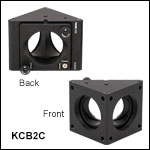
KCB2C
60 mm Cage Mount with Smooth Cage Rod Bores
Application Idea
Using an RBP1 Pin-Aligned, Clamping Post Base and KCB1 Mount to Align a Laser Above the Threaded Holes in an Optical Table
KCB1C
30 mm Cage Mount with Smooth Cage Rod Bores
KCB2
60 mm Cage Mount with Tapped Cage Rod Holes
KCB05C
16 mm Cage Mount with Smooth Cage Rod Bores

Please Wait
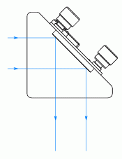
Light Path Through Right-Angle Kinematic Cage Mount
Click to Enlarge
View Imperial Product List
View Metric Product List
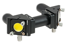
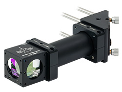
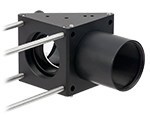
Two C128CC clamps can be used to secure an SC600 Lens Tube Cover between two KCB1 mounts to cover the beam path.
Features
- Mount Optics at 45° with ±4° of Kinematic Adjustment
- Versions Available for Ø1/2" (Ø12.7 mm), Ø1" (Ø25.4 mm), or Ø2" (Ø50.8 mm) Optics
- Compatible with 16 mm, 30 mm, or 60 mm Cage Systems
- KCB05(/M), KCB1(/M), and KCB2(/M) Mounts Have Eight Tapped Holes for Cage Rods
- KCB05C(/M), KCB1C(/M), and KCB2C(/M) Mounts Have Eight Smooth Bores for Cage Rods
- SM-Threaded for Lens Tube Compatibility
- Post Mountable
- Fabricated from Black Anodized Aluminum
- Use RBP1(/M) Pin-Aligned, Clamping Post Base with KCB1(/M) or KCB1C(/M) Mount to Simplify Beam Alignment Over the Threaded Holes in an Optical Table
These Right-Angle Kinematic Cage Mounts provide kinematic tip and tilt adjustment for an optic at a mean angle of 45° relative to the optical axis. They are compatible with Thorlabs' cage systems and have internal SM threads at the input and output ports for mounting lens tubes (see the table below).
Click to Enlarge
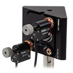
A 30 mm or 60 mm Cage Right-Angle Kinematic Mount can be Motorized with Two MPIA10 Actuators
Click to Enlarge
View Imperial Product List
View Metric Product List
Our Right-Angle Kinematic Mounts Integrate with Cage Systems and Lens Tube Systems
The KCB05(/M), KCB1(/M), and KCB2(/M) mounts have 4-40 tapped holes at the input and output spaced for compatibility with 16 mm, 30 mm, or 60 mm cage systems, respectively. As a result, SRSCA SR Rod Adapters [for Item # KCB05(/M)] or ERSCB ER Rod Adapters [for Item #s KCB1(/M) and KCB2(/M)] are necessary to connect, adjust, and lock two of these right-angle cage mounts together using cage rods.
The KCB05C(/M), KCB1C(/M), and KCB2C(/M) mounts have smooth bores that accept cage rods at the input and output. The KCB05C(/M) mount's bores are spaced for 16 mm cage system compatibility and have a 0.05" (1.3 mm) hex setscrews at each bore to lock an SR cage rod in place. The KCB1C(/M) and KCB2C(/M) mounts have bores spaced for 30 mm or 60 mm cage systems, respectively, and use 5/64" (2 mm) hex setscrews to lock ER cage rods in place. As a result, these mounts can be connected to another right-angle cage mount of the same size without the need for SCRCSA or ERSCB cage rod adapters.
The kinematic tip and tilt adjustment plate on each mount is actuated with fine adjustment screws for smooth, high-resolution movement. Optics are held with a nylon-tipped setscrew, and loaded from the backside. This arrangement does not limit the maximum thickness of the optic. The adjustment plate is double-bored for two lines of stable contact with the mating optic.
The ten right angle mounts listed below are sized to incorporate Ø1/2" (Ø12.7 mm), Ø1" (Ø25.4 mm), or Ø2" (Ø50.8 mm) optics within a 16 mm Cage System, 30 mm Cage System, or 60 mm Cage System, respectively.
The RBP1(/M) Pin-Aligned, Clamping Post Base, available below, is designed to align the surface of a mirror mounted in a KCB1(/M) or KCB1C(/M) Right-Angle Kinematic Mirror Mount above a hole in the optical table, simplifying the process of aligning a reflected laser beam over the table's threaded holes. To use this clamping base, the KCB1 series mount must be attached to a Ø1" or Ø25 mm Pillar Post.
| Item # | KCB05(/M) | KCB05C(/M) | KCB1(/M) | KCB1C(/M) | KCB2(/M) | KCB2C(/M) |
|---|---|---|---|---|---|---|
| Mirror Size | Ø1/2" (Ø12.7 mm) | Ø1" (Ø25.4 mm) | Ø2" (Ø50.8 mm) | |||
| Cage System Compatibility |
4-40 Taps with Spacing for 16 mm Cage System |
Ø4 mm Bores with Spacing for 16 mm Cage System |
4-40 Taps with Spacing for 30 mm Cage System |
Ø6 mm Bores with Spacing for 30 mm Cage System |
4-40 Taps with Spacing for 60 mm Cage System |
Ø6 mm Bores with Spacing for 60 mm Cage System |
| Lens Tube Interfaces | Internal SM05 Threads | Internal SM1 Threads | Internal SM2 Threads | |||
| Post Mounting Taps | 4-40 and 8-32 (M3 and M4) | 8-32 and 1/4"-20 (M4 and M6) | 8-32 and 1/4"-20 (M4 and M6) | |||
Cage System Overview
The Cage Assembly System provides a convenient way to construct large optomechanical systems with an established line of precision-machined building blocks designed for high flexibility and accurate alignment.
16 mm, 30 mm, and 60 mm Cage System Standards
Thorlabs offers three standards defined by the center-to-center spacing of the cage assembly rods (see image below). The 16 mm cage, 30 mm cage, and 60 mm cage standards are designed to accommodate Ø1/2", Ø1", and Ø2" optics, respectively. Specialized cage plates that allow smaller optics to be directly inserted into our larger cage systems are also available.
Standard Threads
The flexibility of our Cage Assembly System stems from well-defined mounting and thread standards designed to directly interface with a wide range of specialized products. The three most prevalent thread standards are our SM05 Series (0.535"-40 thread), SM1 Series (1.035"-40 thread), and SM2 Series (2.035"-40 thread), all of which were defined to house the industry's most common optic sizes. Essential building blocks, such as our popular lens tubes, directly interface to these standards.

An example of the standard cage plate measurements determining cage system compatibility.
| Standard Cage System Measurements | |||
|---|---|---|---|
| Cage System | 16 mm | 30 mm | 60 mm |
| Thread Series | SM05 | SM1 | SM2 |
| Rod to Rod Spacing | 16 mm (0.63") | 30 mm (1.18") | 60 mm (2.36") |
| Total Length | 25 mm (0.98") | 41 mm (1.60") | 71.1 mm (2.80") |
| Cage Components | ||
|---|---|---|
| Cage Rods | 16 mm | These rods are used to connect cage plates, optic mounts, and other components in the cage system. The SR Series Cage Rods are compatible with our 16 mm cage systems, while the 30 mm and 60 mm cage systems use ER Series Cage Rods. |
| 30 mm | ||
| 60 mm | ||
| Cage Plates | 16 mm | These serve as the basic building blocks for a cage system. They may have SM-threaded central bores, smooth bores sized for industry standard optics or to accommodate the outer profile of our SM Series Lens Tubes, or specialized bores for other components such as our FiberPorts. |
| 30 mm | ||
| 60 mm | ||
| Optic Mounts | 16 mm | Thorlabs offers fixed, kinematic, rotation, and translation mounts specifically designed for our Cage Systems. |
| 30 mm | ||
| 60 mm | ||
| Cage Cubes | 16 mm | These cubes are useful for housing larger optical components, such as prisms or mirrors, or optics that need to sit at an angle to the beam path, such as beamsplitters. Our cage cubes are available empty or with pre-mounted optics. |
| 30 mm | ||
| 60 mm | ||
| Replacement Setscrews | Replacement setscrews are offered for our 16 mm (SS4B013, SS4B025, and SS4B038) and 30 mm (SS4MS5 and SS4MS4) cage systems products. | |
| Post and Breadboard Mounts and Adapters | Mounting options for cage systems can be found on our Cage System Construction pages. Cage Systems can be mounted either parallel or perpendicular to the table surface. | |
| Size Adapters | Cage System Size Adapters can be used to integrate components from different cage system and threading standards. | |
| Specialized Components | Thorlabs also produces specialized cage components, such as Filter Wheels, a HeNe Laser Mount, and a FiberPort Cage Plate Adapter, allowing a wide range of our products to be integrated into cage-mounted optical systems. Explore our Cage Systems Visual Navigation Guide to see the full range of Thorlabs' cage components. | |
| Posted Comments: | |
user
(posted 2019-10-30 07:30:32.82) Have you considered versions of these right angle kinematic cage mounts with lockable adjusters, similar to those on the KS05? These would be useful for more permanent installations. Also, a cover plate to go over the adjusters and the back of the mirror would be useful for the same. Thank you. llamb
(posted 2019-10-31 09:16:07.0) Thank you for contacting Thorlabs and for your feedback. We will consider both of these product improvements within our internal engineering forum. hnguyen
(posted 2015-08-14 17:11:04.083) You specify that the minimum thickness for optics that can be secured by KCB05 mount is 3 mm. Is there any way to hold a 1-mm thick optics in KCB05 mount? If so, please let me know your solution by e-mail as soon as possible. Thank you. jlow
(posted 2015-08-25 04:20:07.0) Response from Jeremy at Thorlabs: You will have to use a 2mm spacer so that the setscrew can engage your optic or permanently epoxy the optic in the mount. samzlemieux
(posted 2013-04-23 19:10:38.887) We are currently using the KCB1 in order to make a horizontal beam vertical. Right now, I can't find a way to put a post and a holder underneath the part, because the screw holes are located on the sides (with my configuration).
If I use the side holes, I need a set of ankles, which make the set-up more unstable.
Is there any way to add a plate or something? tcohen
(posted 2013-04-24 21:33:00.0) Response from Tim at Thorlabs: You could use two standard TR posts with an RA90 to access the (now side) mounting holes. The cage rods are on a 30mm square matrix, so you are able to flip the part 90 degrees and still use the cage system with ER rods as well (with a C1026 clamp if support is required). Alternatively, we have parts such as the MA45-2 (45 degree adapter) which may be preferred if you aren't using the cage axis/SM1 ports. Thorlabs
(posted 2010-10-07 15:42:23.0) Response from Javier at Thorlabs to jnichols: I will contact you directly to discuss your application requirements. jnichols
(posted 2010-10-04 14:24:03.0) Would you be able to make a larger version of the Right Angle Kinematic Cage Mount that fits the SM3 lens tubes? klee
(posted 2009-10-22 11:23:09.0) A response from Ken at Thorlabs to bioyuyu: You will receive a quotation from our sales department shortly. bioyuyu
(posted 2009-10-22 04:18:01.0) Dear sir,
Please send me the quotation form excluding shipping charge by e-mail for the following product.
ITEM:HRP350*1 and KCB1*4
All the Best,
Pei-Yu Huang
National Synchrotron Radiation Research Center
Tel +886-3-5780281 ext 7327 Tyler
(posted 2008-11-03 16:36:46.0) A response from Tyler at Thorlabs to jouko.viitanen: A member of our technical support department will send you the distance specification that you requested as well as a labeled drawing so that everyone is clear as to the dimension being discussed. Please feel free to contact our tech support department for clarification on any product dimension. Alternatively, the 3D model can be downloaded from our website using the link found under the "Drawings and Documents" tab. Thank you fro sending us your request. If you find that our product is not suitable for your needs please consider letting us know. We are always looking for ways to improve the flexibility and breadth of our product lines in order to better serve the research community. jouko.viitanen
(posted 2008-10-27 06:48:27.0) Please provide the additional information on this product :
distance of the intersection position from the 45 degree surface,
when the beams from the two SM1 tube entrances are entering to it at the
tube central axes. We are looking for an attachment block for a
fast steering mirror component that has a tilting mirror at the
front surface. Possibly it could be connected using KCB1 if the
kinematic mount of KCB1 is removed, provided that its 45 degree surface is
in level, or not too far from the intersection point. acable
(posted 2007-01-12 13:46:38.0) Photo is too hard to read, please give at least on tight shot, can't see how the optic is mounted. |

- Eight 4-40 Tapped Holes to Mate with 16 mm Cage Systems
- Mounts Ø1/2" (12.7 mm) Optics at a 45° Angle to the Optical Axis
- Provides ±4º Kinematic Tip and Tilt Adjustment
- Compatible with SM05-Threaded (0.535"-40) Lens Tubes
- Post Mountable:
- KCB05: One 4-40 Tap and One 8-32 Tap (for Mini-Series and Ø1/2" Posts)
- KCB05/M: One M3 Tap and One M4 Tap (for Mini-Series, Ø1/2", and Ø1" Posts)
The KCB05(/M) Mirror Mount provides provides ±4° of kinematic tip and tilt adjustment for a Ø1/2" optic positioned at a mean angle of 45° to the optical axis. Entrance and exit ports are equipped with an SM05-threaded (0.535"-40) hole. The KCB05(/M) has eight 4-40 tapped holes spaced for compatibility with our 16 mm cage systems. SRSCA SR Rod Adapters are necessary to effectively connect, adjust, and lock two of these right angle cage mounts together within the cage system. The kinematic tip and tilt adjustment plate on these cubes is actuated with M3 x 0.25 adjustment screws that allow for smooth, high-resolution movement of 0.25 mm (0.01") per turn. Two of these adjusters include removable knobs, while the third must be tuned with a 5/64" (2 mm) hex key or balldriver.
A nylon-tipped setscrew is used to secure Ø1/2" (12.7 mm) optics using a 0.05" (1.3 mm) hex key or balldriver in the mount's rear-loading, double-bored hole. The rear loading design does not limit the thickness of the mounted optic and the mounted optic remains accessible even after the mount is fitted with cage rods or lens tubes. The minimum thickness for optics that can be secured by these mounts is 0.12" (3 mm).

- Eight Ø0.16" (Ø4.0 mm), 0.20" (5.0 mm) Deep Bores to Mate with 16 mm Cage Systems
- Mounts Ø1/2" (12.7 mm) Optics at a 45° Angle to the Optical Axis
- Provides ±4º Kinematic Tip and Tilt Adjustment
- Compatible with SM05-Threaded (0.535"-40) Lens Tubes
- Post Mountable:
- KCB05C: One 4-40 Tap and One 8-32 Tap (for Mini-Series, Ø1/2", and Ø1" Posts)
- KCB05C/M: One M3 Tap and One M4 Tap (for Mini-Series, Ø1/2", and Ø1" Posts)
The KCB05C(/M) Mirror Mount provides ±4° of kinematic tip and tilt adjustment for a Ø1/2" optic positioned at a mean angle of 45° to the optical axis. Entrance and exit ports are equipped with an SM05-threaded (0.535"-40) hole. Eight 0.20" (5.0 mm) deep bores, spaced for compatibility with our 16 mm Cage System, accept SR Cage Rods, which can be locked in place using the included 0.05" (1.3 mm) hex setscrews. This design allows multiple 16 mm cage components to be directly interfaced without the need for SRSCA SR Rod Adapters. The kinematic tip and tilt adjustment plate on these cubes is actuated with M3 x 0.25 adjustment screws that allow for smooth, high-resolution movement of 0.25 mm (0.01") per turn. Two of these adjusters include removable knobs, while the third must be tuned with a 1.5 mm hex key or balldriver.
A 0.05" (1.3 mm) hex, nylon-tipped setscrew is used to secure Ø1/2" (12.7 mm) optics in the mount's rear-loading, double-bored hole. Two clearance cuts, positioned on opposite sides of the optic bore, maximize the clear aperture for transmitted light and provide easy access to mounted optics. Due to the rear-loading design, the mounted optic remains accessible even after the mount is fitted with cage rods or lens tubes. The mount accepts optics ≥0.12" (3 mm) thick.

 Click to Enlarge
A KCB1 and high power beamsplitter cube with a beam path enclosed by an aluminum lens tube cover and two C128CC clamps.
- Eight 4-40 Tapped Holes to Mate with 30 mm Cage Systems
- Mounts Ø1" (25.4 mm) Optics at a 45° Angle to the Optical Axis
- Provides ±4º Kinematic Tip and Tilt Adjustment
- Compatible with SM1-Threaded (1.035"-40) Lens Tubes
- Post Mountable:
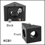
The KCB1(/M) cube provides kinematic tip and tilt of an optic held in a mounting plate whose mean horizontal position is at a 45° angle. Entrance and exit ports are equipped with an SM1-threaded (1.035"-40) bore. The KCB1(/M) has eight 4-40 tapped holes center-to-center spaced to mate with our 30 mm cage system standard. ERSCB ER Rod Adapters are necessary to effectively connect, adjust, and lock two of these right angle cage mounts together within the cage system. The kinematic tip and tilt adjustment plate on these cubes is actuated with 100 TPI (Threads per Inch) adjustment screws that allow for smooth, high-resolution movement of 0.01" (0.254 mm) per rotation. Two of these adjusters include removable knobs, while the third must be tuned with a 5/64" (2 mm) hex key or balldriver.
A nylon-tipped setscrew is used to secure Ø1" (25.4 mm) optics using a 5/64" (2 mm) hex key or balldriver via the mounts' rear-loading, double-bored hole. The rear loading design does not limit the maximum thickness of the mounted optic and the mounted optic remains accessible even after the mount is fitted with cage rods or lens tubes. The minimum thickness for optics that can be secured by these mounts is 0.12" (3 mm), and optics thinner than 0.12" (3 mm) will need to be combined with an optic spacer.

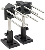
Click to Enlarge KCB1C Mount with Smooth Bores (Right) Directly Attached to a KCB1 Mount with Tapped Holes (Left)
- Eight 0.25" (6.35 mm) Deep Smooth Bore Holes to Mate with 30 mm Cage Systems
- Mounts Ø1" (25.4 mm) Optics at a 45° Angle to the Optical Axis
- Provides ±4º Kinematic Tip and Tilt Adjustment
- Compatible with SM1-Threaded (1.035"-40) Lens Tubes
- Post Mountable:
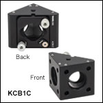
The KCB1C(/M) cube provides kinematic tip and tilt of an optic held in a mounting plate whose mean horizontal position is at a 45° angle. Entrance and exit ports are equipped with an SM1-threaded (1.035"-40) bore and four 0.25" (6.35 mm) deep smooth bore holes center-to-center spaced to mate with our 30 mm cage system standard. The cage rods are secured by eight setscrews using a 5/64" (2 mm) hex key or balldriver. This design allows multiple 30 mm cage components to be directly interfaced without the need for ERSCB ER Rod Adapters. The kinematic tip and tilt adjustment plate on these cubes is actuated with removable 100 TPI (Threads per Inch) adjustment screws that allow for smooth, high-resolution movement of 0.01" (0.254 mm) per rotation. Two of these adjusters include removable knobs, while the third must be tuned with a 5/64" (2 mm) hex key or balldriver.
A nylon-tipped setscrew is used to secure Ø1" (25.4 mm) optics using a 5/64" (2 mm) hex key or balldriver via the mounts' rear-loading, double-bored hole. This hole features a clearance cut that provides a maximum clear aperture for any transmitted light and allows easy access to mounted optics. The rear loading design does not limit the thickness of the mounted optic and the mounted optic remains accessible even after the mount is fitted with cage rods or lens tubes. The minimum thickness for optics that can be secured by these mounts is 0.12" (3 mm), and optics thinner than 0.12" (3 mm) will need to be combined with an optic spacer.

- Eight 4-40 Tapped Holes to Mate with 60 mm Cage Systems
- Mounts Ø2" (Ø50.8 mm) Optics at a 45° Angle to the Optical Axis
- Provides ±4º Kinematic Tip and Tilt Adjustment
- Compatible with SM2-Threaded (2.035"-40) Lens Tubes
- Post Mountable:
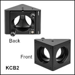
The KCB2(/M) Right-Angle Kinematic Cage Mount provides kinematic tip and tilt adjustment of a Ø2" (Ø50.8 mm) optic held in a mounting plate with a mean horizontal position at a 45° angle. The ports are equipped with SM2-threaded (2.035"-40) bores. The KCB2(/M) has eight 4-40 tapped holes spaced to mate with our 60 mm cage systems. ERSCB ER Rod Adapters are necessary to effectively connect, adjust, and lock two of these right angle cage mounts together within the cage system. The ±4° kinematic tip and tilt adjustment plate is actuated with three 100 TPI (Threads per Inch) adjustment screws for smooth, high-resolution movement of 0.01" (0.254 mm) per rotation. Two of these adjusters include removable knobs, while the third must be tuned with a 5/64" (2 mm) hex key or balldriver.
A nylon-tipped setscrew is used to secure Ø2" (Ø50.8 mm) optics using a 5/64" (2 mm) hex key or balldriver via the mounts' rear-loading, double-bored hole. The rear loading design does not limit the maximum thickness of the mounted optic and the mounted optic remains accessible even after the mount is fitted with cage rods or lens tubes. The minimum thickness for optics that can be secured by these mounts is 0.24" (6 mm).

- Eight Smooth Bore Holes to Mate with 60 mm Cage Systems
- Mounts Ø2" (Ø50.8 mm) Optics at a 45° Angle to the Optical Axis
- Provides ±4º Kinematic Tip and Tilt Adjustment
- Compatible with SM2-Threaded (2.035"-40) Lens Tubes
- Post Mountable:
The KCB2C(/M) Right-Angle Kinematic Cage Mount provides kinematic tip and tilt adjustment of a Ø2" (Ø50.8 mm) optic held in a mounting plate with a mean horizontal position at a 45° angle. The ports are equipped with SM2-threaded (2.035"-40) bores and smooth bore holes spaced to mate with our 60 mm cage system standard. The cage rods are secured by setscrews using a 5/64" (2 mm) hex key or balldriver. This design allows multiple 60 mm cage components to be directly interfaced without the need for ERSCB ER Rod Adapters. The ±4° kinematic tip and tilt adjustment plate is actuated with three 100 TPI (Threads per Inch) adjustment screws for smooth, high-resolution movement of 0.01" (0.254 mm) per rotation. Two of these adjusters include removable knobs, while the third must be tuned with a 5/64" (2 mm) hex key or balldriver.
A nylon-tipped setscrew is used to secure Ø2" (Ø50.8 mm) optics using a 5/64" (2 mm) hex key or balldriver via the mounts' rear-loading, double-bored hole. When used with transmissive optics, two clearance cuts around this hole provide a Ø1.26" (Ø32.0 mm) nominal clear aperture for any transmitted light. The rear loading design does not limit the maximum thickness of the mounted optic and the mounted optic remains accessible even after the mount is fitted with cage rods or lens tubes. The minimum thickness for optics that can be secured by these mounts is 0.24" (6 mm).

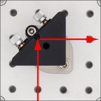
Click to Enlarge Alignment of Laser Beam Along Holes of Optical Table Using an RBP1 Post Base
Click to Enlarge
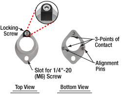
Top and Bottom View of the RBP1 Post Base
- Ideal for Aligning a Laser Beam Along the Threaded Holes of an Optical Table
- Compatible with Imperial and Metric Optical Tables and Ø1" or Ø25 mm Pillar Posts
- Alignment Pins and Attachment Screw Position the Front Surface of the Mirror in a KCB1(/M), KCB1C(/M), KCB1E(/M), or KCB1EC(/M) Mount Above a Hole in the Table
- Post Rotates Freely When Locking Screw is Loosened
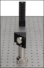
Click to Enlarge Using a BHM6 Ruler and RBP1 Base to Align a KCB1 Mount
The RBP1(/M) Pin-Aligned, Clamping Post Base is designed to simplify aligning a laser beam over the threaded holes in an imperial or metric optical table by holding the front surface of a mirror mounted in a KCB1(/M), KCB1C(/M), KCB1E(/M), or KCB1EC(/M) Right-Angle Kinematic Mirror Mount above a hole in the table. The clamping post base accepts Ø1" (Ø25 mm) Pillar Posts, to which the right-angle mirror mount can be connected as shown in the image to the left; note that the base does not accept pedestal posts. Alignment pins on the bottom of the RBP1(/M) clamp fit into the holes on an optical table, which sets the mount in the correct position, while a 1/4"-20 (M6) cap screw and washer (not included) secure the clamp to the table. The body of the clamp is made of stainless steel, with an additional anodized aluminum piece that works with the locking screw to lock the post to the clamp.
Once the RBP1(/M) is attached to the table, the angle of the post can be set so that the mirror sends the beam along the general direction of the holes in the table by aligning the center of the back of the mount over the locking screw side of the clamp, as shown in the image above and to the right. To secure the post in place, tighten the locking screw with a 3/16” (5 mm) hex key or balldriver. The post clamping mechanism uses three points of contact for stable mounting (see the image to the upper right). The knobs on the mirror mount can then be used for further precise alignment of the beam. We recommend the BHM6 Magnetic Beam Height Ruler with Dowel Pins as an ideal tool for aligning a laser with a table's hole pattern using the RBP1(/M) post bases, as it places a series of alignment holes at different heights above two threaded holes in the table (see the image to the left).
 Products Home


 Zoom
Zoom

 Right-Angle Kinematic Mirror Mounts