30 mm Cage Cube Rotating Platforms
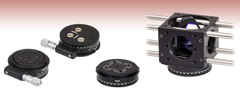
- Stable Platform to Mount Optics Within 30 mm Cage Cubes
- Provides Continuous Rotation While Mounted
- Compatible with 30 mm Cage Cubes and Optic Holders
B4CRP
Bottom
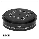
B3CR
Top
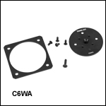
B3CR with C6WA Adapter Allowing
all Four Cage Rods to Pass
Through C6WR Cage Cube
Application Idea

Please Wait
| 30 mm Cage Cubes and Accessories | ||||
|---|---|---|---|---|
 |
 |
 |
 |
 |
| Cage Cubes | Optic Mounts | Platforms | Rotating Platforms | Cover Plates |
Features
- 30 mm Cage Cube-Compatible Platforms
- Continuous Rotation While Mounted to a Cage Cube
- Kinematic Options Available
The 30 mm cage cube platforms offered here are designed to hold our 30 mm cage cube optic mounts. These platforms are ideal for building optical setups involving prisms, beamsplitters, and other optics that are compatible with our 30 mm cage system. The platforms featured here can be mounted to either the top or bottom of a 30 mm cage cube and are locked down with the included screws (see Video 1.1). Both platforms can be continuously rotated, even after locking down to a cage cube; giving the user dynamic control over the position of the optic within a cage cube. The B4C platform offers additional precision rotation with a side located micrometer and kinematic translation via three set screws located on the bottom of the platform.
When using these platforms with a C6WR cage cube, there will be insufficient clearance to pass the two cage rods nearest the platform all the way through the cage cube. For the B3CR(/M) and B4CRP(/M) cube platforms, the C6WA Mounting Adapter can be used to provide clearance for all four cage rods without sacrificing mounting surface area (see Video 1.2). Alternatively, the cage rods can still be passed through the through-holes opposite the rotating platform or the C6WR can be turned 90° with all four cage rods threaded into the 4-40 holes on opposite sides of the C6WR.
Video 1.1 Animation demonstrating how to attach a platform to a 30 mm cage cube.
Video 1.2 Animation demonstrating how the C6WA Platform Adapter allows cage rods to pass through a 30 mm cage cube.
Cage System Overview
The Cage Assembly System provides a convenient way to construct large optomechanical systems with an established line of precision-machined building blocks designed for high flexibility and accurate alignment.
16 mm, 30 mm, and 60 mm Cage System Standards
Thorlabs offers three standards defined by the center-to-center spacing of the cage assembly rods (see Figure 14A). The 16 mm cage, 30 mm cage, and 60 mm cage standards are designed to accommodate Ø1/2", Ø1", and Ø2" optics, respectively. Specialized cage plates that allow smaller optics to be directly inserted into our larger cage systems are also available.
Standard Threads
The flexibility of our Cage Assembly System stems from well-defined mounting and thread standards designed to directly interface with a wide range of specialized products. The three most prevalent thread standards are our SM05 Series (0.535"-40 thread), SM1 Series (1.035"-40 thread), and SM2 Series (2.035"-40 thread), all of which were defined to house the industry's most common optic sizes. Essential building blocks, such as our popular lens tubes, directly interface to these standards.

Figure 14A An example of the standard cage plate measurements determining cage system compatibility.
| Standard Cage System Measurements | |||
|---|---|---|---|
| Cage System | 16 mm | 30 mm | 60 mm |
| Thread Series | SM05 | SM1 | SM2 |
| Rod to Rod Spacing | 16 mm (0.63") | 30 mm (1.18") | 60 mm (2.36") |
| Total Length | 25 mm (0.98") | 41 mm (1.60") | 71.1 mm (2.80") |
| Cage Components | ||
|---|---|---|
| Cage Rods | 16 mm | These rods are used to connect cage plates, optic mounts, and other components in the cage system. The SR Series Cage Rods are compatible with our 16 mm cage systems, while the 30 mm and 60 mm cage systems use ER Series Cage Rods. |
| 30 mm | ||
| 60 mm | ||
| Cage Plates | 16 mm | These serve as the basic building blocks for a cage system. They may have SM-threaded central bores, smooth bores sized for industry standard optics or to accommodate the outer profile of our SM Series Lens Tubes, or specialized bores for other components such as our FiberPorts. |
| 30 mm | ||
| 60 mm | ||
| Optic Mounts | 16 mm | Thorlabs offers fixed, kinematic, rotation, and translation mounts specifically designed for our Cage Systems. |
| 30 mm | ||
| 60 mm | ||
| Cage Cubes | 16 mm | These cubes are useful for housing larger optical components, such as prisms or mirrors, or optics that need to sit at an angle to the beam path, such as beamsplitters. Our cage cubes are available empty or with pre-mounted optics. |
| 30 mm | ||
| 60 mm | ||
| Replacement Setscrews | Replacement setscrews are offered for our 16 mm (SS4B013, SS4B025, and SS4B038) and 30 mm (SS4MS5 and SS4MS4) cage systems products. | |
| Post and Breadboard Mounts and Adapters | Mounting options for cage systems can be found on our Cage System Construction pages. Cage Systems can be mounted either parallel or perpendicular to the table surface. | |
| Size Adapters | Cage System Size Adapters can be used to integrate components from different cage system and threading standards. | |
| Specialized Components | Thorlabs also produces specialized cage components, such as Filter Wheels, a HeNe Laser Mount, and a FiberPort Cage Plate Adapter, allowing a wide range of our products to be integrated into cage-mounted optical systems. Explore our Cage Systems Visual Navigation Guide to see the full range of Thorlabs' cage components. | |
Reading a Vernier Scale on a Linear Main Scale
Vernier scales are typically used to add precision to standard, evenly divided scales (such as the scales on Thorlabs' rotation, goniometric, or translation mounts). A vernier scale has found common use in many precision measurement instruments, the most common being calipers and micrometers. The vernier scale uses two scales side-by-side: the main scale and the vernier scale. The direct vernier scale has a slightly smaller spacing between its tick marks owing to the vernier scale having N ticks for every N - 1 ticks on the main scale. Hence, the lines on the main scale will not line up with all the lines on the vernier scale. Only one line from the vernier scale will match well with one line of the main scale, and that is the trick to reading a vernier scale.
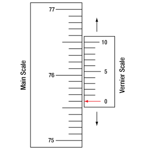
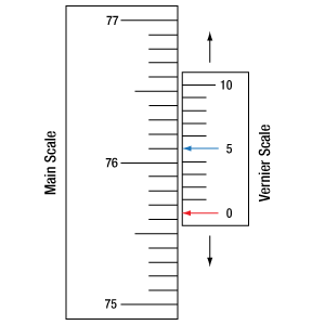
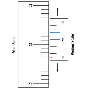
Figures 130A through 130C show a linear vernier scale system for three different situations. In each case, the scale on the left is the main scale, while the small scale on the right is the vernier scale. When reading a vernier scale, the main scale is used for the gross number, and the vernier scale gives the precision value. In this manner, a standard ruler or micrometer can become a precision instrument.
The 0 on the vernier scale is the "pointer" (marked by a red arrow in Figures 130A through 130E) and will indicate the main scale reading. In Figure 130A we see the pointer is lined up directly with the 75.6 line. Notice that the only other vernier scale tick mark that lines up well with the main scale is 10. Since the pointer lines up with the main scale’s 75.6, the reading from Figure 130A is 75.60 (in whatever units the instrument measures).
That is essentially all there is to reading a vernier scale. It's a very straightforward way of increasing the precision of a measurement instrument. To expound, let’s look at Figure 130B. Here we see that the pointer is no longer aligned with a line on the main scale, but instead it is slightly above 75.6 and below 75.7; thus, the gross measurement is 75.6. The first vernier line that coincides with a main scale line is the 5, shown with a blue arrow. The vernier scale gives the final digit of precision; since the 5 is aligned to the main scale, the precision measurement for Figure 130B is 75.65.
Since this vernier scale is 10% smaller than the main scale, moving the vernier scale by 1/10 of the main scale will align the next vernier marking. This asks the obvious question: what if the measurement is within the 1/10 precision of the vernier scale? Figure 130C shows just this. Again, the pointer line is in between 75.6 and 75.7, yielding the gross measurement of 75.6. If we look closely, we see that the vernier scale 7 (marked with a blue arrow) is very closely aligned to the main scale, giving a precision measurement of 75.67. However, the vernier scale 7 is very slightly above the main scale mark, and we can see that the vernier scale 8 (directly above 7) is slightly below its corresponding main scale mark. Hence, the scale on Figure 130C could be read as 75.673 ± 0.002. A reading error of about 0.002 would be appropriate for
this instrument.
Click to Enlarge
Figure 130A An example of how to read a vernier scale. The red arrow indicates what is known as the pointer. Since the tick mark labeled 10 on the vernier scale aligns with one of the tick marks on the main scale, this vernier scale is reading 75.60 (in whatever units the instrument measures).
Click to Enlarge
Figure 130B The red arrow indicates the pointer and the blue arrow indicates the vernier line that matches the main scale. This scale reads 75.65.
Click to Enlarge
Figure 130C The red arrow indicates the pointer, and the blue arrow indicates the vernier line that matches the main scale. This scale reads 75.67 but can be accurately read as
75.673 ± 0.002.
Reading a Vernier Scale on a Rotating Main Scale
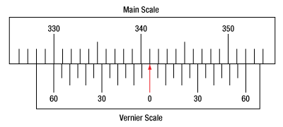
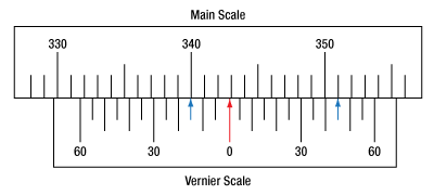
The vernier scale may also be used on rotating scales where the main scale and vernier scale do not share units. Figures 130D and 130F show a vernier scale system for two different situations where the main scale is given in degrees and the vernier scale has ticks every 5 arcmin (60 arcmin = 1°). In each case, the scale on the top is the main scale, while the small scale on the bottom is the vernier scale.
In Figure 130D we see the pointer is lined up directly with the 341° line. Notice that the only other vernier scale tick marks that line up well with the main scale are ±60 arcmin. Since the pointer lines up with the main scale at 341°, the reading from Figure 130D is 341.00°.
There are two ways to determine the reading if the zero on the vernier scale line is between two lines of the main scale. For the first method, take the line on the left side of the pointer on the vernier scale and subtract that value (in arcmin) from the value on the main scale that is to the right on the main scale. As an example, in Figure 130E the vernier pointer is between 342° and 343°; using the left blue arrow of the vernier scale results in
As we've seen here, vernier scales add precision to a standard scale measurement. While it takes a bit of getting used to, with a little practice, reading these scales is fairly straightforward. Vernier scales, whether they are direct or retrograde*, are read in the same fashion.
*A retrograde vernier scale has a larger spacing between its tick marks with N ticks for every N + 1 ticks on the main scale.
Click to Enlarge
Figure 130D An example of a vernier scale where the main scale and the vernier scale are in different units (degrees and arcmins, respectively). The red arrow indicates the pointer. This scale reads 341.00°.
Click to Enlarge
Figure 130E The red arrow indicates the pointer and the blue arrows give the precision value from the vernier scale.
This scale reads 342.75°.
| Posted Comments: | |
Yuan Gao
(posted 2025-06-16 18:41:54.56) Hi, I have two technical questions about the B4CRP/M:
1) Could you provide the adjustment ranges for tip, tilt, and height? Since these parameters are interdependent, a more specific question might be: what is the thread length of the three adjustment screws?
2) I need to mount a parabolic mirror (e.g., MPD269H-P01) onto the platform. What’s the recommended method for doing this? Is there a suitable adapter available?
Thank you in advance for your help! jdelia
(posted 2025-06-17 12:57:28.0) Thank you for contacting Thorlabs. The B4CRP is designed for +/-3° of tip/tilt when the top of the mounting plate is level with the top of the main body. The adjustment screws ae ¼-80 x ½" and provide 0.25°/rev. We unfortunately do not have a suggested method for interfacing it directly with an OAP. I have reached out to you directly to discuss your application. Luca Ravotto
(posted 2024-02-23 16:18:34.487) I would like to follow up on a question asked above. We use 60 mm cages for a custom built microscope, and we need to precisely control the rotation of a mirror. Currently, we use the LB4C, which is a real pain for precise alignment. If it would be possible to have an adapter plate to mount the B4CRP/M on 60 mm cages, it would really be a game changer for us. Any plans to add such an adapter to your inventory? jdelia
(posted 2024-02-26 11:11:24.0) Thank you for contacting Thorlabs and for providing this feedback. While this is not something we currently offer, I would be happy to pass along your request to our design engineers via our internal suggestion forum for consideration as a future catalog item. Cristian Papusoi
(posted 2023-12-14 18:26:46.587) How can I mount the B4CRP cage rotating platform on a post ? There are no threads on the bottom side for this purpose. Thank you. ksosnowski
(posted 2023-12-20 01:37:31.0) Hello Cristian, thanks for reaching out to Thorlabs. The C4W and C6W cubes could potentially be post-mounted using B1C on the side opposite from B4CRP. You are correct that the B4CRP platform has no post mount, this is due to the placement of the return springs in the platform. Qi Huang
(posted 2023-06-26 15:14:42.21) Hi,
For product B4CRP, do you have a motorized actuator that can replace the micrometer on the stage? We are thinking of motorized rotation using this stage.
Thank you. jdelia
(posted 2023-06-27 12:43:26.0) Thank you for contacting Thorlabs. We unfortunately do not currently offer a motorized actuator compatible with the B4CRP, as this platform utilizes a micrometer with a Ø1/4" smooth mounting barrel, and we do not offer any actuators to match that. We apologize for any inconvenience this may cause. We have also reached out to you directly to discuss your application further. Katsuya Nozawa
(posted 2022-10-27 15:07:40.2) I want to fix a prism on a B4CRP/M rigidly, but I don't want to glue the prism on it directly.
I am very glad if you sell an attachment plate which has holes to fix the plate on B4CRP/M by M3 or M4 screws. cdolbashian
(posted 2022-10-31 01:29:38.0) Thank you for reaching out to us with this inquiry. Depending on the prism needed, you could use something like the PM4, and softly clamp the prism to the B4CRP surface. Sebastian Starosielec
(posted 2021-08-20 05:00:55.457) Dear Sir or Madam,
Is there a way to mount the B4CRP/M into a SM2 thread ? From the dimensions this seems to almost fit. Either by an adapter plate (to clamp the B4CRP like in C4W) or a SM2-threaded housing.
Then one could use the B4CRP vertically in a 60mm cage system, that would offer a very compact rotation/tip/tilt mount e.g. for gratings. YLohia
(posted 2021-08-27 03:09:27.0) Hello, thank you for contacting Thorlabs. Unfortunately, there is no such part at the moment to adapt the B4CRP/M to an SM2 thread at the moment. That being said, we will consider offering such a part in the future. Dan D
(posted 2021-07-02 09:59:22.237) Does the B3CR rotating platform have kinematic tip/tilt adjustment like the B4C platform? YLohia
(posted 2021-07-02 10:29:59.0) The B3CR does not have tip/tilt capability. For that, you would have to use the B4CRP. lebow
(posted 2018-04-19 12:13:35.457) Why don't you make an adapter that will allow the mounting of cage hardware on a 1/2" post. I had our machine shop make a simple 1/4" plate with a 1.75" hole with (3) 4-40 tapped holes to retain the mount. Tapped 8-32 hole in side. Right now you line of cage hardware is extremely restricted. llamb
(posted 2018-04-27 08:31:46.0) Thank you for your feedback. We are always looking to improve our product line. I will reach out to you directly to discuss your customization and add this new idea to our internal product forum. |

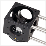
Click to Enlarge Figure G1.2 The B3CR has 6-32 Taps for use with the PM3 to Hold a Right-Angle Prism
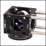
Click to Enlarge Figure G1.1 The B3CR is Compatible with the B5C1 Optic Mount
- Continuously Rotating Cage Cube Mounting Platform
- Brass 1/16" Locking Setscrew to Secure Position
- Compatible with 30 mm Cage Cube Accessories
- Platform Includes Alignment Marks for 5 mm, 10 mm, 20 mm, and 25.4 mm Cube Optics
The B3CR platform mounts on the top or bottom of a C4W or C6WR cage cube. It provides a freely rotating platform that can be used to mount a variety of optics inside the cube. The platform can rotate through the full 360°, and can be locked using the brass setscrew with 1/16" hex.
The 4-40 (M3) tapped holes can mount our Optic Holders (B5C1 shown in Figure G1.1) or the FFM1 Dichroic Holder, while the 6-32 (M4) holes are compatible with the PM3 (PM3/M) Clamping Arm to hold prisms (shown in Figure G1.2). Larger cube-shaped optics and prisms can also be secured with the B6C, which has a swivel head to allow for optic rotation. A Ø25 mm Post Spacer can be placed under the optic to center it in the clear aperture of the cube when using the PM3 or B5C.

Click to Enlarge
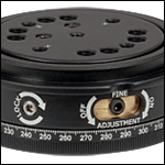
Figure G2.2 Side-located setscrews allow for locking the platform position (LOCK) or enabling and disabling the micrometer control (FINE ADJUSTMENT).

Click to Enlarge
Figure G2.1 Kinematic adjustment screws for fine tip, tilt, and height adjustments are located on the bottom of the platform.
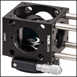
Click to Enlarge Figure G2.3 The B4CRP is Compatible with the B5CT2 Optic Mount
- Kinematic Platform Enables Tip, Tilt, and Height adjustment
- 360° Manual Rotation with ±7° Micrometer-Driven Fine Adjustment
- 1/16" Hex Locking Hex Setscrew to Secure Manual and Micrometer Position
- 1° Resolution Laser Engraved Scale With 5 Arcmin Vernier Scale
- Compatible with all Cage Cube Accessories
The B4CRP (/M) precision platform mounts to the top or bottom of a C4W or C6WR 30 mm cage cube. This precision platform can be freely rotated 360° while mounted to a 30 mm cage cube. Additionally, when engaged, the stage provides a micrometer driven ±7° of fine rotation. A laser engraved scale provides 1° resolution with a 5 arcmin vernier scale. Three kinematic adjustment screws located on the bottom of the platform (see Figure G2.1) allow for fine tip, tilt, and height adjustments; resulting in total and precise control of and optic’s position while mounted in a 30 mm cage cube. The top plate is marked with 3 small Xs, indicating the location of the three kinematic adjustment screws. A 1/16” hex setscrew allows the user to lock the position of the platform while another 1/16” hex setscrew enables or disables micrometer control (see Figure G2.2). Please note that overtightening of the fine adjustment control screw may prevent proper operation of the micrometer.
The 4-40 (M3) tapped holes can mount our Optic Holders (B5CT2 shown in Figure G2.3) or the FFM1 Dichroic Holder, while the 6-32 (M4) holes are compatible with the PM3 (PM3/M) Clamping Arm to hold other components such as prisms. Larger cube-shaped optics and prisms can also be secured with the B6C, which has a swivel head to allow for optic rotation. A Ø25 mm Post Spacer can be placed under the optic to center it in the clear aperture of the cube when using the PM3 or B6C.

Click for Details
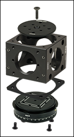
Figure G3.2 The C6WA is shown here with the B3CR. It can be mounted to the C6WR Cage Cube with Thorlabs' Cube Platforms.*
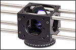
Click for Details Figure G3.1 The C6WA can be used to mount optics with the B5C1 in the C6WR Cage Cube while allowing all four cage rods to be fully inserted in the through holes.
- Mounting Adapter Allows C6WR to House Optics with All Four Cage Rods Inserted
- Compatible with B3C(/M), B4C(/M), B3CR(/M), and B4CRP(/M) Platforms*
- Four 1/4" Long Button-Head Screws Included for Mounting
The C6WA(/M) Platform Adapter Kit allows Thorlabs' Cube Platforms* to be used in conjunction with the C6WR with all four cage rods installed. The C6WA kit consists of two machined components, four 4-40 button-head screws, and a single 4-40 (M3) flat-head screw. A 0.08" (2.0 mm) thick shim allows the mounting platform to mate to the C6WR without interfering with the cage rods while a secondary platform is then installed above the cage rods. The adapter platform has a diameter of 1.65" (41.9 mm) and raises the mounting surface height by 0.27" (6.9 mm).
The C6WA(/M)'s hole pattern consists of four 4-40 (M3) taps compatible with our Optic Holders (B5C1 shown in Figure G3.1) and four 6-32 (M3) tapped holes allowing the use of a PM3 Clamping Arm. When using one of these optic holders or a clamping arm with a rotating cage cube platform and the C6WA, limited fine adjustment with the rotation platform is possible before the top of the mount or clamping arm interferes with the cage rods. This platform adapter is not designed for use with the FFM1.
To use the adapter, place the square shim between the bottom of the C6WR and the cage cube platform (B3C(/M), B4C(/M)*, B3CR(/M)*, or B4CRP(/M)) you wish to mount to the cage cube. Secure the cage cube platform to the cage cube through the holes in the shim using the four 1/4" (6.4 mm) long button-head screws included in the adapter kit (see exploded view in Figure G3.2). Insert the adapter platform through the top hole of the cage cube, angling it as needed to bypass the top cage rods, and attach it to the cage cube platform using the included 4-40 (M3) flat-head screw. Once the adapter platform is installed, the optic holder or clamping arm can be used to mount an optic inside the cage cube.
Please note that the vertical offset created by the raised mounting platform will make any optic mounted using our 30 mm-Cage-Cube-Compatible Optic Mounts no longer centered with respect to the SM1-threaded ports.
*The C6WA(/M) is not compatible with versions of the B3CR/M sold before March 26, 2014, or B3C(/M) and B4C(/M) platforms sold before December 5, 2012. If you have an older model of the B3CR/M, B3C(/M), or B4C(/M) platforms and would like to exchange it for the new version, please contact Technical Support.
 Products Home


 Zoom
Zoom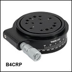
 30 mm Cage Cube Rotation Platforms