1.533 µm Frequency-Locked Laser
- Frequency Stabilized to NIST-Traceable Transition of C2H2
- High Side Mode Suppression Ratio (SMSR) of at Least 35 dB
- Stability Better than ±25 MHz
- Fiber-Coupled Optical Output
LLD1530
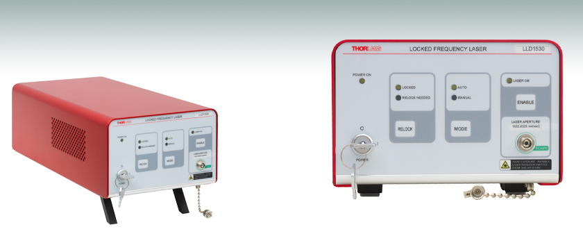
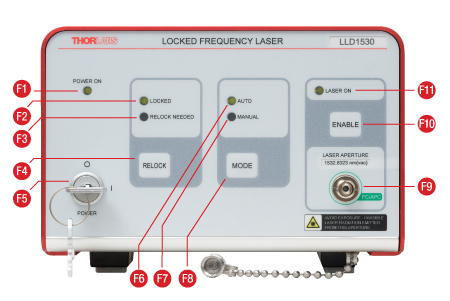
Front Panel displays LED status indicators, includes a toggle between AUTO and MANUAL modes, and provides a control to trigger laser frequency re-locking.

Please Wait
 Click to Enlarge
Click for Raw Data
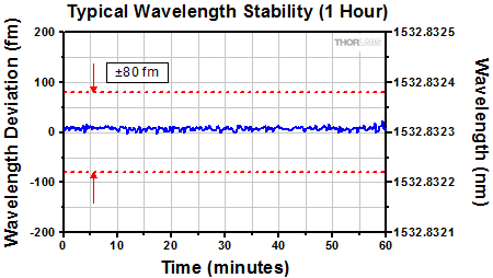
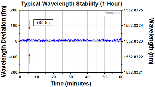
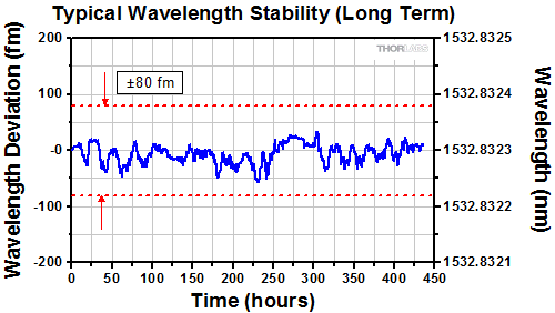
Figure 1.1 The typical vacuum emission wavelength data for the LLD1530 plotted above resulted from measuring frequency stability data using two LLD1530 lasers and a beat note approach; one LLD1530 was intentionally operated with a slightly detuned optical frequency to generate the beat note. The frequency measurements were converted to wavelength for the plot. The lasers operated in MANUAL Mode under ambient conditions, and no re-locking procedures were performed during data acquisition. The limits of the
 Click to Enlarge
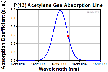
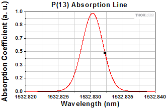
Figure 1.2 The LLD1530 uses the side-of-fringe locking technique. The target vacuum wavelength (red square) coincides with the half width at half maximum (HWHM) point at 23 °C on the long-wavelength side of the P(13) acetylene gas absorption line (fringe). See the Frequency Lock tab for more information.
Features
- Frequency Reference Laser System Based on Distributed Feedback (DFB) Laser
- Vacuum Emission Wavelength of 1532.8323 nm
- Frequency Stabilized to a NIST-Traceable Transition of Acetylene (C2H2)
- Excellent Low-Drift Performance
- Front Panel LEDs and Digital I/O Signals Indicate Status of Frequency Lock
- Two Operating Modes
- AUTO: Laser Frequency Automatically Re-Locked as Necessary
- MANUAL: Laser Frequency Re-Lock Procedure is Exclusively Triggered by User
Applications
- Interferometry
- Fourier Transform Infrared (FTIR) Instrumentation Reference
- Gas Sensing
- Instrument Calibration
- Telecom (ITU Dense Wavelength Division Multiplexing (DWDM) 12.5 GHz Grid Slot at 195.5875 THz)
Thorlabs' LLD1530 Frequency-Locked Laser is a narrow linewidth, DFB-laser-diode-based, turnkey system with a vacuum emission wavelength of 1532.8323 nm and a high SMSR of at least 35 dB. The laser frequency is actively stabilized to a National Institute of Standards and Technology (NIST)-traceable molecular transition of acetylene and has an absolute accuracy at start-up that is better than ±25 MHz. The emission frequency immediately after start-up is then maintained with a ±25 MHz stability, providing an overall frequency accuracy of ±50 MHz. The LLD1530 is an accurate frequency reference designed to provide low-noise laser emission with excellent frequency stability, accuracy, and precision immediately at start-up. This source is ideal for use in demanding FTIR instrumentation, instrument calibration, gas sensing, and coherent telecommunications applications.
Our frequency reference source can be powered on, frequency locked, and operated over a temperature range from 10 °C to 40 °C. If the ambient temperature is within this range when the laser is powered on and enabled, the sophisticated start-up algorithm ensures that the laser emission is locked at the target frequency as soon as the start-up procedure concludes. Frequency locking is performed using the P(13) absorption line of the acetylene gas absorption spectrum and the side-of-fringe locking technique. The vacuum wavelength of the laser is stabilized to the point marked in red on the graph of the P(13) absorption line shown in Figure 1.2.
AUTO Mode
Operating the LLD1530 in AUTO mode is recommended, as this mode automatically maintains the laser emission within ±25 MHz of the target frequency. In this mode, the system automatically triggers a frequency re-locking procedure when the absolute difference between the emission frequency and the target frequency exceeds a threshold set close to, but less than, 25 MHz. For more information about the threshold that triggers the frequency re-lock, see the Specs tab. The RELOCK button is not enabled in AUTO mode.
MANUAL Mode
MANUAL mode is intended to be used when a task is intolerant of the variations in the emission intensity and wavelength that occur during the re-locking procedure. The user may toggle between AUTO and MANUAL modes using a button on the front panel. When the operating mode is MANUAL, the red RELOCK NEEDED status LED illuminates at the threshold that would trigger a frequency re-locking procedure in AUTO mode. The LLD1530 will continue to operate, but the specified frequency accuracy cannot be guaranteed while the RELOCK NEEDED status LED is illuminated. When the absolute difference between the emission frequency and the target frequency exceeds 25 MHz, the "LOCKED" status LED is extinguished. When the laser operates in MANUAL mode, the user may initiate the frequency re-locking procedure at any time by pressing the RELOCK button.
Electrical and Optical I/O
The optical output of the LLD1530 is fiber coupled via a FC/APC connector. The female DB9 connector on the back panel offers a digital I/O interface that allows the user to enable the laser, select the operating mode, trigger the frequency re-locking procedure, and obtain operating status information. Please see the Front and Back Panels tab to for an overview of the controls and indicators on the laser housing and the Pin Diagram tab for information about the digital I/O interface.
| Table 2.1 Specifications | ||||
|---|---|---|---|---|
| Typical | Max | |||
| Center Vacuum Wavelength | 1532.8323 | nm | ||
| Stability (Long Term, After Warm Up)a | - | <±10 | ±25 | MHz |
| - | <±0.08 | ±0.2 | pm | |
| - | <±0.00033 | ±0.00085 | cm-1 | |
| Accuracy (at Start Up) | - | <±15 | ±25 | MHz |
| - | <±0.12 | ±0.2 | pm | |
| - | <±0.00050 | ±0.00085 | cm-1 | |
| Precision (at Start Up, After Warm Up)b | - | <1 | - | MHz |
| - | <0.008 | - | pm | |
| - | <0.00003 | - | cm-1 | |
| Laser Linewidth (FWHM)c | - | <3 | - | MHz |
| Side Mode Suppression Ratio (SMSR) | 35 | - | - | dB |
| Relative Intensity Noise (RIN)d | - | 100 | - | dBc/Hz |
| Optical Power Stability (30 minute Duration) | - | 1.1 | - | % |
| Optical Output Powere | - | - | 10 | mW |
| Max Change in Ambient Temperature before Frequency Re-Lock Neededf | ΔT = ±3.5 °C | |||
| Ambient Temperature Change Triggering Frequency Re-Lock (AUTO Mode Only)g | ΔT = ±(0.9)*3.5 °C | |||
| Laser Classh | Class 1 | |||
| Optical Fiber Type | SMF-28 Ultra | |||
| Connectors | ||||
| Optical Fiber Connector | FC/APC | |||
| Digital Control Interface Connector | D-Sub 9 Pin Female | |||
| Environmental, Power, and Physical | ||||
| Operating Temperature Rangei | 10 °C to 40 °C | |||
| Storage Temperature Range | 0 °C to 60 °C | |||
| Power Requirements | 100 - 240 VAC, 0.3 A, 50 - 60 Hz | |||
| Fuse | 0.5 A, 250 V, Type T, 5 x 20 mm | |||
| Maximum Operating Altitude | 2000 m Above Sea Level | |||
| Dimensions | 149.8 mm x 104.2 mm x 318.2 mm (5.90" x 4.10" x 12.53") |
|||
| Weight | 3.1 kg (6.83 lbs) | |||
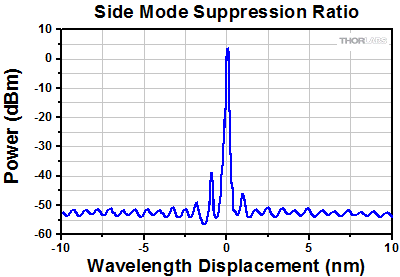
Figure 2.2 Plot showing a typical side mode suppression ratio (SMSR) of the DFB laser integrated into the LLD1530 laser reference system.
Click to Enlarge
Figure 2.3 The typical variation in the LLD1530's vacuum emission wavelength over one hour. Frequency stability data were measured using two LLD1530 lasers and a beat note approach; one LLD1530 was intentionally operated with a slightly detuned optical frequency to generate the beat note. The frequency measurements were converted to wavelength for the plot.
Figure 2.4 These data were measured using Thorlabs' OSA205C and show the typical long-term vacuum wavelength stability of the LLD1530. All data were acquired while the lasers operated in MANUAL Mode under ambient conditions, and no re-locking procedures were performed. The limits of the 1532.8323 nm ± 80 fm long-term stability specification for the LLD1530 are denoted by dashed red lines.
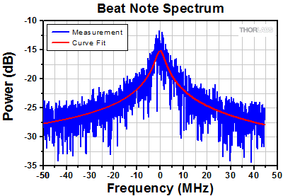
Figure 2.5 Typical beat note spectrum between two LLD1530 locked-frequency laser sources (blue curve), plotted with a Lorentzian curve fit (red curve). The beat note was recorded over 10 µs using a 150 MHz detector. A 2.5 MHz FWHM laser linewidth was derived from the measurement data and the 3.6 MHz FWHM of the curve fit. For more information, please see the "Linewidth Measurement Using the Beat Note Technique" section on this tab.
Linewidth Measurement Using the Beat Note Technique
The interference signal required by this measurement technique was generated by combining the emission of two LLD1530 lasers, with the optical frequency of one intentionally detuned slightly. Both lasers had spectra with Lorentzian line shapes and the same linewidth, the polarizations of their light beams were not orthogonal, and their laser noise was not correlated. The sinusoidal envelope of their interference signal (beat note) was detected using the 150 MHz indium gallium arsenide (InGaAs)-based PDA10CF photodetector and recorded by an oscilloscope. The oscillation frequency of this detected beat signal was equal to the difference between the optical frequencies of the two optically-coupled lasers. A 10 µs segment of the beat signal was fast Fourier transformed (FFT) into the spectral domain, and the blue trace plots these data in Figure 2.5.
The linewidth of the laser under test was determined mathematically from these measurement data using the properties of the detection process, the FFT, and the two laser beams. The photodetector, by detecting intensity, effectively performed a complex multiplication of the two incident optical signals. This time-domain multiplicative product was then Fourier transformed using an FFT. The result was a convolution of the two beams' Lorentzian line shapes in the frequency domain, which is the beat note spectrum plotted in Figure 2.5. The beat note spectrum also has a Lorentzian line shape, as the convolution of two Lorentzian functions is another Lorentzian function. The relationship between the linewidths of the two lasers, ΓLaser, and the linewidth of the resulting convolution, ΓConv, is:
ΓLaser =2-1/2ΓConv. (1)
A Lorentzian curve fit, which is plotted in red in Figure 2.5, was used to find the 3.6 MHz linewidth of the beat note spectral data, and Equation 1 was used to calculate the 2.5 MHz linewidth of the LLD1530.
Vacuum Wavelength vs. In-Air Wavelength
Specifications for the LLD1530 Laser Reference source are referenced to the vacuum wavelength to make them universally applicable. The in-air wavelength is equal to the vacuum wavelength divided by the local refractive index of air, which varies with changes in ambient conditions such as air pressure, temperature, and humidity As the vacuum wavelength is invariant to environmental conditions, different measurements that are referenced to the vacuum wavelength may be directly compared.
Front and Back Panels
Click to Enlarge
Figure 3.1 Front Panel
Click to Enlarge
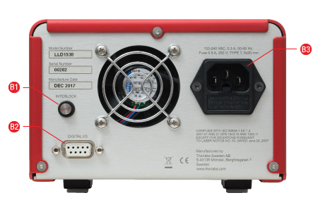
Figure 3.2 Back Panel
| Front Panel | |
|---|---|
| Callout | Description |
| F1 | LED Indicates Power is Supplied to Unit |
| F2a | LED Indicates Laser Frequency is Locked within ±25 MHz Range |
| F3a | LED Indicates Laser Frequency is Near the Edge of the ±25 MHz Range |
| F4 | Button to Trigger Laser Re-Lock Procedure (Enabled in Manual Mode Only) |
| F5 | Key Switch Provides Power to the Unit |
| F6 | LED Indicates Operation in AUTO Mode |
| F7 | LED Indicates Operation in MANUAL Mode |
| F8 | Button to Toggle between Automatic and Manual Modes |
| F9 | Laser Emission Output Aperture, FC/APC Connector |
| F10 | Button to Enable Laser Emission |
| F11 | LED Indicating Laser is On and Laser Emission Present |
| Back Panel | |
|---|---|
| Callout | Description |
| B1 | Laser Interlock Jack |
| B2 | Digital I/O Interface, Female DB9 Connector |
| B3 | AC Power Cord Connector |
Digital I/O Pin Assignments
The D-Sub 9 Pin female DIGITAL I/O interface on the rear panel can be used to operate and receive operating status information from the LLD1530. This requires the laser sytem to be powered on and for the key switch to be turned to position l. Control commands are sent, and system status information is received, as low (GND) or high (5 V) voltage signals.
The digital interface inputs are activated by setting Pin 1 low (GND). While Pin 1 is held low, all buttons on the front panel are disabled and the instrument is controlled solely via digital signals sent to the D-Sub 9 connector. All LEDs on the front panel indicate the current state of the instrument independent of the state of Pin 1.
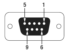
| Pin | Function | State | Type | |
|---|---|---|---|---|
| Low (GND) | High (5 V) | |||
| 1a | Enable Laser | Enabled | Disabled | Input |
| 2b | Trigger Relock Procedure | Relock | - | Input |
| 3 | Select Operating Mode | Manual | Automatic | Input |
| 4 | System Staus Indicator | - | Relock Needed | Output |
| 5 | System Staus Indicator | - | Locked | Output |
| 6 | System Staus Indicator | - | Laser On | Output |
| 7 | Not Connected | - | - | |
| 8 | Not Connected | - | - | |
| 9 | GND | - | - | |
Vacuum Wavelength and Optical Frequency:
When discussing the laser emission of the LLD1530, it is sometimes convenient to speak in terms of vacuum wavelength and other times in terms of optical frequency. The vacuum wavelength is found by dividing the speed of light in vacuum by the laser's optical frequency. (The wavelength of the laser emission in air is found by dividing the vacuum wavelength by the refractive index of air.)
Frequency Locking the Laser Emission of the LLD1530
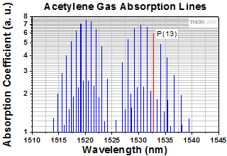
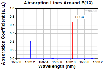
The LLD1530 maintains the emission frequency of the distributed feedback (DFB) laser within a narrow ±50 MHz range around the target frequency. This range takes into account the ±25 MHz initial accuracy of the frequency lock and the subsequent ±25 MHz operational stability. These specifications are achieved using an acetylene gas cell reference, whose absorption coefficients are plotted in Figure 5.1. The DFB laser has a vacuum emission wavelength that intersects the P(13) absorption line, which is also referred to as a fringe. This makes the P(13) fringe a convenient wavelength reference for the LLD1530. The P(13) fringe is highlighted in red in Figure 5.1 and in Figure 5.2, which shows that the P(13) fringe is isolated from and comparatively stronger than neighboring absorption features.
The frequency lock is acquired and maintained using the side-of-fringe locking technique. It is implemented by diverting a small amount of light from the DFB laser and coupling it into the gas cell. The intensity transmitted by the gas cell is monitored while the vacuum wavelength of the DFB laser is tuned to a point on the long-wavelength side of the P(13) fringe. This point is always close to the half width at half maximum (HWHM), and the target position at 23 °C is indicated on the plot of the fringe in Figure 5.3. The DFB laser's full width at half maximum (FWHM) frequency linewidth is <3 MHz, while the FWHM of the P(13) fringe is approximately 0.5 GHz. As the DFB laser's linewidth is a couple of orders of magnitude narrower than the width of the P(13) line, the intensity of the transmitted light varies significantly with changes in the vacuum emission wavelength of the DFB laser.
During the frequency-locking procedure, the position of the laser frequency lock on the side of the fringe is adjusted, according to the ambient temperature, to correspond to the target frequency. While the center frequency of the P(13) gas line varies negligibly, the width of the gas line experiences both temperature-dependent Doppler and collisional broadening. The influence of temperature on the width of the gas line has been well characterized and documented in published literature, and our sophisticated locking algorithm references these data. A benefit of tuning the laser to coincide with the steep region of the fringe around the HWHM is that even a small change in the vacuum emission wavelength results in a significant change in the intensity transmitted by the gas cell. In addition, positive and negative changes in the transmitted intensity are unambiguously correlated with negative and positive changes in the laser's wavelength, respectively.
The frequency-lock procedure is performed at start-up, and the laser operates at its target vacuum emission wavelength as soon as laser emission is enabled and the LOCKED LED is illuminated. The gas cell parameters were designed to ensure the low influence of temperature fluctuations on the output frequency, but other components in the LLD1530 exhibit modest temperature-dependent optical properties that affect the intensity of light coupled into the gas cell. The re-locking procedure, which in AUTO mode is automatically triggered when needed, easily compensates for these.
Click to Enlarge
Figure 5.1 The P(13) fringe, highlighted in red, is used to frequency lock the LLD1530.
Click to Enlarge
Figure 5.2 The P(13) fringe in relation to neighboring absorption features.
Click to Enlarge
Figure 5.3 The LLD1530 uses the side-of-fringe locking technique. The target vacuum wavelength (black square) coincides with the HWHM point at 23 °C on the long-wavelength side.
| Posted Comments: | |
Keishi Kubo
(posted 2022-05-17 23:34:03.03) Please tell me the literature of frequency lock
Is it possible to change the lock frequency in the range of 1510 to 1540? cdolbashian
(posted 2022-05-27 12:34:57.0) Thank you for reaching out to us Keishi. Unfortunately, this device cannot be tuned by the user. As a potential custom, we can tune it +/- 1 nm about it's design wavelength. For a tunable source, perhaps the TLX1, a C-Band tunable laser, would be more suitable for your application. I have reached out to you directly to discuss you application. |
 Products Home


 Click to Enlarge
 1.533 µm Frequency-Locked Laser