 Products Home / Technical Resources / Insights / Lab Practices Insights / Accessing Centrally Located Mounting Points on a Translation Stage
Accessing Centrally Located Mounting Points on a Translation Stage


Please Wait
How are the large mounting holes (counterbores) at the middle of a translation stage used?
The mounting points used to secure some translation stages to a table or breadboard are located closer to the middle, rather than the perimeter, of the stage. Securing and releasing the stage from the mounting surface requires centering the top plate over the bottom (base) plate. When this is done, the oversized through holes on the top plate form a counterbore with the smaller through holes on the bottom plate.
Cap screws can then be inserted through the oversized holes in the top plate and screwed into the mounting surface to secure the stage. This is demonstrated using an MT1B linear translation stage. The stage can be released by loosening and removing the screws via the same holes.
Click to Enlarge
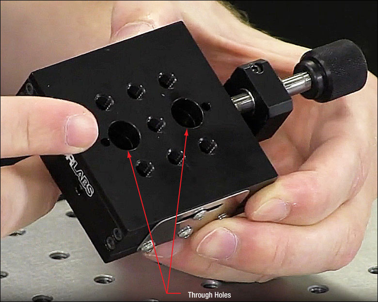
Figure 2: The two large through holes on the top plate of the stage provide access to the mounting points on the bottom of the stage.

Click to Enlarge
Figure 1: Through holes near the center of the stage's bottom plate are mounting points used to secure the stage to an optical table or breadboard.
Video Clip 1: The procedure for securing an MT1B linear translation stage to an optical table is demonstrated in this video clip.
Click to Enlarge
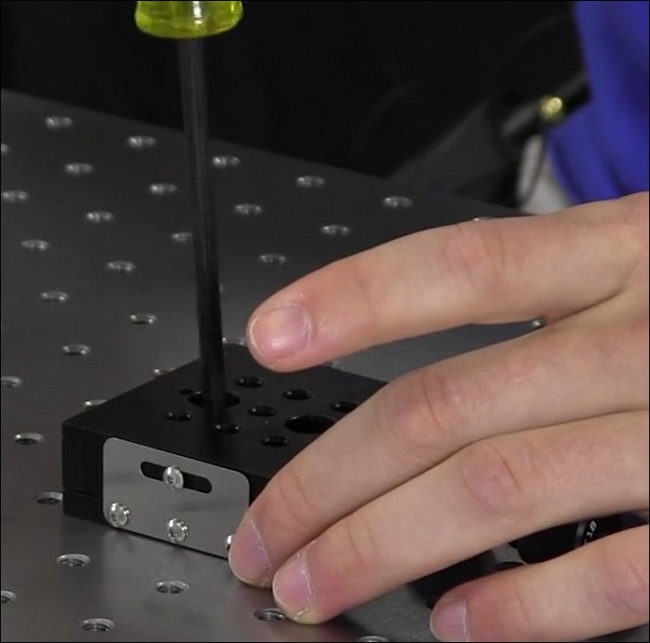
Figure 3: Each large through hole on the top surface of the stage provides the tip of a 3/16" (5 mm) ball driver access to the 1/4"-20 (M6) cap screws, which were previously inserted and used to secure the stage to the mounting surface.
Accessing the Mounting Points
The mounting points (Figure 1) are through holes located in the base plate, which is part of the stage's fixed world. The diameters of these through holes are large enough to pass the threads, but not the heads, of 1/4"-20 (M6) cap screws. Access to these mounting points is via the larger through holes (Figure 2) in the top plate, which is part of the stage's moving world.
However, accessing the mounting points requires aligning the top and bottom plates. The adjuster can be used to translate the top plate into alignment, so that each large through hole in the top plate is concentric with a smaller through hole in the bottom plate, forming counterbores. If a cap screw is inserted, threads first, into one of the through holes in the top plate, it should be possible to guide the threads through the hole in the bottom plate.
Secure the Stage First, then Mount Components
After the top and bottom plates are aligned, place the stage on the table or breadboard with the base plate in contact with the mounting surface. Align the counterbores with the threaded holes in the mounting surface, then insert a 1/4"-20 (M6) cap screw, from the top of the stage, into each through hole and then screw it into the table (Figure 3).
Since the top plate translates relative to the base plate, the top plate blocks access to the mounting points in general use. In addition, components mounted on the stage typically cover one or both of the through holes on the top plate. Due to this, it can be inconvenient to relocate the stage in the middle of an experiment. It is recommended that the stage be secured in an optimal location before mounting components on it.
Alternatively, a base plate like the MT401, which is designed for the MT stages, can be used to provide unobstructed mounting points at the perimeter of the stage. The stage is secured to the base plate as described here, and then the mounting slots on the base plate are used to secure the stage to a mounting surface.
Watch the Procedure Demonstrated
The procedure is demonstrated in the video clip (Clip 1), and the full video includes additional Insights on translation stages, including the procedure for replacing its adjuster screw with a motorized actuator.
|
Looking for more Insights? |
Date of Last Edit: Sept. 8, 2020 |
| Posted Comments: | |
| No Comments Posted |