 Products Home
Silicon Photomultiplier (SiPM) Amplified Detectors
- Ideal for Low Light Applications and Single Photon Detection
- Reflective Pulse Compression (RPC) Circuit Produces Fast Signals and Improved Dynamic Range
- Integrated Thermoelectric Cooler (TEC) Reduces Dark Counts and Provides Consistent Gain
- Undamaged by Overexposure to Incident Light
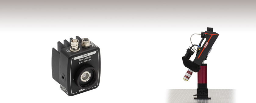
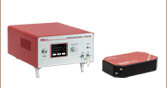
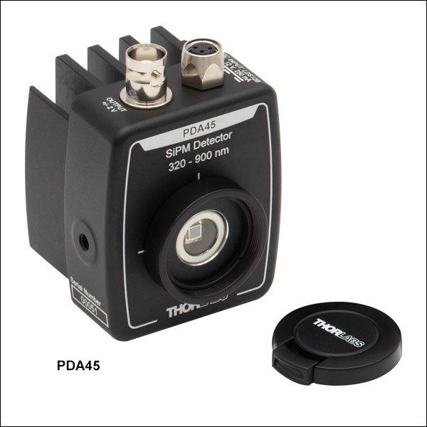
PDA45
SiPM Amplified Detector
3 mm x 3 mm Active Area
The PDA45 SiPM Amplified Detector as Part of the Prelude® Functional Imaging Microscope


Please Wait
| SiPM Selection Guide | ||||||
|---|---|---|---|---|---|---|
| Item # | Wavelength Range |
Active Area | Pixel Pitch |
Dark Counts (Typ. / Max) |
Photon Detection Efficiency (PDE) |
Sample Data |
| PDA44 | 320 - 900 nm | 1.3 x 1.3 mm | 50 µm | 5 kcps / 13 kcps | 40% |  |
| PDA45 | 3 x 3 mm | 25 kcps / 72 kcps | ||||
| PDA40 | 350 - 1000 nm | Ø1.5 mm | 25 µm | 35 kcps / 90 kcps |
30% |  |
| PDA41 | 50 µm | 40% |  |
|||
| PDA42 | Ø3.0 mm | 25 µm | 140 kcps / 350 kcps |
30% | |
|
| PDA43 | 50 µm | 40% | |
|||
Click to Enlarge
A comparison of the photon detection efficiency (PDE) of the PDA series SiPM detectors.
Features
- Single Photon Detection Capability
- Consistent Single Photon Pulse Energy Allows Counting Multiple Concurrent Photons
- Visible and NIR Responsivity
- Low Max Dark Counts
- Patent-Pending Reflective Pulse Compression (RPC) Circuit Removes SiPM Recharge Tail for Cleaner Signals
- Integrated TEC Reduces Dark Counts and Provides Consistent Gain
- Power Supply Included
Thorlabs' Silicon Photomultiplier (SiPM) Amplified Detectors, also known as Multi-Pixel Photon Counters (MPPC), consist of multiple Geiger mode avalanche photodiode (APD) pixels, providing photon counting capability. Each pixel in the SiPM detector can be biased above its breakdown voltage, making them well suited to very low light detection. The detectors are designed to operate in the visible and NIR and feature a variety of active areas and responsivities.
Each SiPM detector is an array of pixels, where each pixel consists of a series combination of an avalanche photodiode and a quenching resistor. These pixels are connected in parallel and arranged to provide four different active areas: 1.3 mm x 1.3 mm, Ø1.5 mm, Ø3.0 mm, or 3 mm x 3 mm and come in two different pixel pitches, or sizes: 25 µm or 50 µm. An external bias is applied to the SiPM detector so that the APD pixels operate above their breakdown voltage, creating a strong electric field. When the absorption of a single photon generates an electron-hole pair, the electric field accelerates the electrons, causing the production of secondary electrons by impact ionization. This resulting avalanche constitutes the gain, also known as the multiplication factor "M", of the SiPM detectors and varies depending on the amount of bias applied. More information on this operating principle can be found in the Tutorial tab.
The SiPM detectors are temperature stabilized via a built-in Thermoelectric cooler (TEC) to achieve low maximum dark counts ranging from 13 kcps to 350 kcps, depending on model and settings. These SiPM detectors also feature a variable bias level, which can be used to increase the gain and photon detection efficiency (PDE) of the detectors; however, increasing the bias level will also increase crosstalk behavior and amplify the dark current, increasing the amplitude of existing dark counts. Increasing the bias level will also improve the transit time spread, lowering the variation in time required for a pixel to output a signal after the incidence of light. In general, the applied bias level can be set higher for applications for high gain or PDE or lower for applications requiring low noise. The bias level can be controlled via a knob on the side of the detectors, with steps labeled 1 through 10; for information on the voltage levels for each step, see the Bias Levels table on the Specs tab.
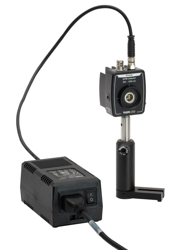
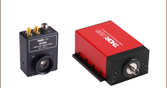
Click to Enlarge
The PDA40 with the Included LDS12B power supply. Replacement power supplies are sold below.
Each model of SiPM detector provides a different set of specifications, with varying combinations of pixel size, active area, and sensitivity. Typically, larger pixel sizes provide higher gain and PDE, while smaller pixel sizes offer faster responsivity and a wider dynamic range. Detectors with larger active areas are more suitable for applications requiring wider dynamic range, while smaller active areas provide higher response speeds and lower dark counts. Please see the Specs tab for complete specifications on all models. The PDE of these SiPM detectors is comparable to the quantum efficiency (QE) of photomultiplier tubes (PMTs); however, the SiPM detectors provide greater dynamic range as shown in the Comparison tab. These SiPM detectors also utilize a Thorlabs patent-pending integrated Reflective Pulse Compression (RPC) circuit, which effectively removes the cell recharge tail from a single electron response, resulting in a cleaner and more distinguishable signal. For more information on the RPC circuit and comparisons to PMTs, see the Signal Characterization tab.
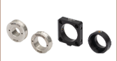
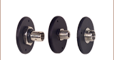
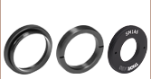
All SiPM detectors have external SM1 (1.035"-40) threading and include a detachable SM1T1 internally SM1-threaded adapter and an SM1RR retaining ring to provide compatibility with Ø1" lens tubes. Thorlabs' D4T dovetails provide compatibility for systems that require quickly adding or removing the detectors, or rotating them for best alignment. Each unit's housing also features two universal taps which accept both 8-32 and M4 screws, allowing the detectors to be mounted in a horizontal or vertical orientation using a Ø1/2" Post.
Power Supply
The LDS12B power supply, a ±12 V linear power supply that supports input voltages of 100, 120, and 230 VAC, is included with each SiPM amplified detector along with a region-specific power cord. Replacement power supplies are available separately below. Before connecting the power supply to mains voltage, ensure that the mains voltage switch on the power supply is set to the proper voltage range. The power supply should always be powered up using the power switch on the power supply itself. Hot plugging the unit is not recommended.
The specifications in the table below are typical values taken with the ambient temperature, Ta, at 25 °C and the detector temperature at -10 °C. The bias level is equal to Vbr + 5 V unless otherwise noted.
| Item # | PDA44 | PDA45 | PDA40 | PDA41 | PDA42 | PDA43 |
|---|---|---|---|---|---|---|
| Wavelength Range | 320 nm - 900 nm | 350 nm - 1000 nm | ||||
| Peak Sensitivity | 450 nm | 600 nm | ||||
| Active Area | 1.3 mm x 1.3 mm | 3 mm x 3 mm | Ø1.5 mm | Ø1.5 mm | Ø3.0 mm | Ø3.0 mm |
| Photon Detection Efficiency (PDE)a | 40% | 30% | 40% | 30% | 40% | |
| Pixel Pitch | 50 µm | 25 µm | 50 µm | 25 µm | 50 µm | |
| Number of Pixels | 667 | 3600 | 2876 | 724 | 11344 | 2836 |
| Fill Factor | 74% | 63% | 81% | 63% | 81% | |
| Dark Counts (Typ. / Max.) | 5 / 13 kcps | 25 / 72 kcps | 35 / 90 kcps | 140 / 350 kcps | ||
| Breakdown Voltage (Vbr) | 51.1 ± 5 V | 40.5 ± 5 V | ||||
| Recommended Bias (V) | Vbr + 3 V | Vbr + 5 V | ||||
| Photon Pulse Height | ~100 mV | |||||
| Photon Pulse Widthb | 4 ns | |||||
| Crosstalk Probability | 3% | 1.5% | 5% | 1.5% | 5% | |
| Gain | 1.7 x 10⁶ | 0.9 x 10⁶ | 3.6 x 10⁶ | 0.9 x 10⁶ | 3.6 x 10⁶ | |
| Sample Data (Click to Enlarge) | |
|
|
|
|
|
| Window Material | Borosilicate Glass | |||||
| Window Refractive Index | 1.52 | |||||
| Cooling | Two-Stage TE-Cooled | |||||
| Cooling Set Point | -10 °C | |||||
| Power Consumptionc | 11 W | |||||
| Output Voltage | ±2 V (Into 50 Ohm Load) | |||||
| Operating Voltage | 100 / 120 / 230 VAC ± 10% 50 - 60 Hz | |||||
| Operating Temperature (Non-Condensing) | 10 - 35 °C | |||||
| Storage Temperature | 0 - 55 °C | |||||
This represents the typical bias level for each setting. A device specific data sheet with recommended bias settings is included with each SiPM detector.
| Bias Levels (± 1.5 VDC) | ||||||
|---|---|---|---|---|---|---|
| Setting | PDA44 | PDA45 | PDA40 | PDA41 | PDA42 | PDA43 |
| 1 | 50.0 | 39.5 | ||||
| 2 | 52.0 | 41.2 | ||||
| 3 | 54.0 | 42.8 | ||||
| 4 | 56.0 | 44.5 | ||||
| 5 | 57.8 | 46.3 | ||||
| 6 | 59.8 | 48.0 | ||||
| 7 | 61.7 | 49.7 | ||||
| 8 | 63.7 | 51.5 | ||||
| 9 | 65.5 | 53.0 | ||||
| 10 | 67.5 | 54.8 | ||||
Operating Principle of Single Photon Detectors
Avalanche photodiodes (APDs) operated in the Geiger Mode have the ability to detect single photons. This single photon sensitivity can be achieved by biasing the APD above the breakdown voltage (Point A in Fig. 1). The APD will remain in a metastable state until a photon arrives and generates an avalanche (Point B). This avalanche is quenched by a quenching resistor inside the APD (Point C), which lowers the bias voltage below the breakdown voltage (labeled VBR in Fig. 1).
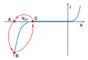
Figure 1: Current Voltage Characteristics of an Avalanche Photodiode Operated in Geiger Mode
Afterwards the excess bias voltage can be restored. During this time, which is known as the pulse dead time of the diode, the APD is insensitive to any other incoming photons. Spontaneously triggered avalanches are possible while the diode is in a metastable state. If these spontaneous avalanches occur randomly, they are called dark counts. If the spontaneously triggered avalanches are correlated in time with a pulse caused by a photon, it is called an afterpulse. To block such afterpulses in the measurement, an additional pulse dead time can be set using software for the counting modules, which will cause the internal counter of the single photon detector to ignore all pulses occurring during this pulse dead time.
Each silicon photomultiplier (SiPM) detector consists of an array of pixels, with each pixel containing series combination of an APD and quenching resistor. When light enters one pixel of the SiPM, there is a chance that secondary photons generated by the avalanche process are detected by neighboring pixels, causing them to produce their own pulses; this phenomenon is called crosstalk.
Definitions
Geiger Mode: In this mode, the diode is operated slightly above the breakdown threshold voltage. Hence, a single electron-hole pair (generated by absorption of a photon or by a thermal fluctuation) can trigger a strong avalanche. Each pixel in an SiPM detector includes an APD in Geiger Mode.
Dark Count Rate: This is the average rate of registered counts in the absence of any incident light and determines the minimum count rate at which the signal is dominantly caused by real photons. The false detection events are mostly of thermal origin and can therefore be strongly suppressed by using a cooled detector.
Dead Time is the time interval a pixel spends in its recovery state. During this time, it is effectively blind to incoming photons. The dead time fraction, which is an inherent feature of an active quenching circuit, may be defined as the ratio of missed to incident events. The time that multiple pixels in an SiPM detector are dead simultaneously will have an effect on the detector's dynamic range.
Afterpulsing: During an avalanche, some charges can be trapped inside the high field region of a pixel. When these charges are released, they can trigger an avalanche. These spurious events are called Afterpulses. The life of those trapped charges is on the order of a few tenths of a microsecond. Hence, it is likely that an afterpulse occurs directly after a signal pulse.
Crosstalk occurs when the avalanche generated by one pixel triggers a secondary avalanche in an adjacent pixel. The likelihood that crosstalk occurs, known as the crosstalk probability, has nearly no temperature dependence within the operating temperature range of the detector.
SiPM Signal Characterization
The typical output waveform of an SiPM detector has several different key features that should be noted, as shown in the image in the bottom left. The output pulse is relative to the number of photons incident on the detector; multiple photons on the detector active area will result in pulses at multiples of the single photoelectron (1 p.e.) response. Changes in the applied bias level can be used to increase or decrease the amplitude of this 1 p.e. response, also known as a single electron response (SER), with a level close to 3 V to 5 V higher than the breakdown voltage (Vbr) yielding a nominal SER of approximately 100 mV.
The typical output pulse for a SiPM detector SER has a very fast rising leading edge, followed by a relatively slowly decaying tail. By employing a proprietary integrated Reflective Pulse Compression (RPC) circuit, Thorlabs' PDA series of SiPM detectors produce a signal that effectively removes the cell recharge tail from the SER pulse. This results in a cleaner, more distinguishable signal as shown below.
Output pulses may also be the result of dark current electrons, which are those electrons generated in the absence of any incident light. These events are typically 1 p.e. in amplitude and are indistinguishable from pulses generated by photons. Dark counts are mostly of thermal origin and therefore are strongly suppressed by the integrated TEC in the SiPM detectors.
During an avalanche, some charges can be trapped inside the high field region, for a time period on the order of a few tenths of a microsecond. When released, these charges can trigger avalanches of their own, which give rise to spurious events know as afterpulses. Given the delay in triggering an avalanche, these afterpulses occur after those pulses generated by valid photon counts or dark count pulses and are generally smaller than 1 p.e.
As SiPM detectors are multi-pixel devices, it is possible for the emitted photon of one pixel to reach an adjacent pixel, resulting in the near simultaneous pulse response of the second pixel. This is known as crosstalk and presents itself as a 2 p.e. output pulse that is indistinguishable from a two-photon event.
In addition to affecting the amplitude of an SER, applied bias levels also influence the dark current and crosstalk behavior exhibited by a SiPM detector. Increasing the bias level will result in an increase in crosstalk probability and gain, leading to an amplification of the dark current, so for applications requiring low noise it is recommended to keep the bias level low. Setting the bias level too high can result in overexposure of the SiPM detector, saturating the system and causing the detector to shut down due to thermal reasons. Once the temperature returns to a nominal value, which typically takes a few seconds, the SiPM detector will automatically begin collecting signal again; unlike photomultiplier tubes (PMTs), this overexposure does not risk damage and does not require additional user input or power cycling. To avoid this down time, the bias level can be lowered or an ND filter installed to limit the incident light, or both.
Click to Enlarge
A comparison of the simulated uncompensated single electron response (SER) and the SER of a pulse using Thorlabs' Reflective Pulse Compression (RPC) circuit.

Click to Enlarge
The cumulative capture of the output signal of an SiPM detector.
Comparison to Photomultiplier Tubes
Silicon photomultipliers (SiPMs) are often compared to photomulplier tubes (PMTs) due to similarities in their operation and characteristics. Both detectors are capable of amplifying very weak signals and have similar levels of gain, with PMTs generally covering larger active areas and SiPMs being more compact in size. While the detectors have comparable detection efficiencies, SiPMs require much lower operating voltages, are immune to magnetic fields, and provide greater dynamic range.
A direct comparison of imaging using both a PMT and an SiPM can be seen in the video to the right. A Bergamo® Multiphoton Imaging Microscope was used to examine GFP-labeled brain tissue, using multiphoton laser excitation at 920 nm with a 525 nm bandpass filter. A 50:50 beam splitter was used to provide identical illumination to a PMT2101 photomultiplier tube and a PDA45 silicon photomultiplier simultaneously. As the laser power is increased the PMT becomes oversaturated and shuts down, while the SiPM continues imaging, displaying its additional dynamic range. This comparison also shows the SiPM matching the image quality of the PMT detector.
| Posted Comments: | |
Jiaze Yin
(posted 2024-03-29 14:45:17.993) Very looking forward to this product! What is the bandwidth of this series, can it used for fluoresce lifetime imaging? ksosnowski
(posted 2024-04-22 02:11:53.0) Hello Jiaze, thanks for reaching out to Thorlabs. The Signal Characterization tab on this webpage includes some typical output pulse examples, from the width of these pulses we expect the upper bandwidth to be in the neighborhood of 300MHz, however at this time we have not tested the exact frequency response or cutoff frequency of the device. These SiPMs are intended as an alternative to PMTs in imaging systems, with similarly high sensitivity from the SiPM's avalanche photodiode array, which is generally useful for fluorescence experiments. I have reached out directly to discuss this application in further detail. 公憲 前田
(posted 2023-10-13 20:20:02.24) この新しいDetectorPDA45に興味があります.蛍光顕微鏡の発光の定量測定を考えていますが,さしあたってはフォトンカウンティングではなくDCでの測定,ピコアンメータへの接続による発光量の定量測定や低周波数ロックインアンプでの利用を考えています.子のディテクタはフォトンカウンティングが強調されていますが,ガイガーモードでの使用しかできないのでしょうか?それとも一般のPMT同様のCWでの利用も可能でしょうか?よろしくお願いします. ksosnowski
(posted 2023-10-18 03:05:18.0) Thanks for reaching out to Thorlabs. You asked about using these detectors with CW sources. As these PDA series Avalanche Detectors operate in the Geiger mode, the dead time after an incoming pulse may make this unsuitable for CW applications. We do have APDs operating in a standard DC bias mode like our APD130A which may be more suitable for this application. My colleagues from your local Tech Support team have reached out directly to discuss your application in further detail. |

 Zoom
Zoom- Wavelength Ranges: 320 nm - 900 nm or 350 nm - 1000 nm
- Four Available Active Areas: 1.3 mm x 1.3 mm, 3 mm x 3 mm, Ø1.5 mm, or Ø3.0 mm
- Pixel Pitch of 25 µm or 50 µm Available
- Low Max Dark Counts
- High Photon Detection Efficiency (PDE): 30% or 40%
- Adjustable Bias Levels
Thorlabs' Silicon Photomultiplier (SiPM) Amplified Detectors provide high photon detection efficiency (PDE) from visible to NIR wavelengths. The adjustable bias level allows the user to optimize for higher PDE and gain (higher bias) or lower amplitude dark counts and crosstalk probability (lower bias). Unlike photomultiplier tubes (PMTs), these SiPM detectors are immune to magnetic fields and cannot be damaged by unwanted ambient light. The SiPM detectors are comprised of a large array of Geiger mode avalanche photodiodes (APDs) and quenching resistors connected in parallel, providing a large active area and wide dynamic range.
For integration into optical systems, each SiPM detector has external SM1 (1.035"-40) threading for compatibility with Ø1" lens tubes. A detachable SM1T1 coupler, which adapts the external threading to an internal SM1 thread, an SM1RR retaining ring, and an SM1EC2B dust cap are included with the detectors. Thorlabs' D4T dovetails provide compatibility for systems that require quickly adding or removing the detectors, or rotating them for best alignment. Each detector features two universal taps which accept both 8-32 and M4 screws, allowing either horizontal or vertical post mounting using Ø1/2" Posts. A ±12 V linear power supply supporting input voltages of 100, 120, and 230 VAC, along with a region-specific power cord, is included with each detector.

 Zoom
Zoom
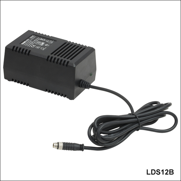
- Replacement Power Supply for Silicon Photomultiplier (SiPM) Amplified Detectors
- ±12 VDC Power Output
- Current Limit Enabling Short Circuit and Overload Protection
- On/Off Switch with LED Indicator
- Switchable AC Input Voltage (100, 120, or 230 VAC)
- 2 m (6.6 ft) Cable with LUMBERG RSMV3 Male Connector
- UL and CE Compliant
The LDS12B ±12 VDC Regulated Linear Power Supply is intended as a replacement for the supply included with our SiPM amplified detectors sold on this page. The cord has three pins: one for ground, one for +12 V, and one for -12 V (see diagram above). This power supply ships with a location-specific power cord. This power supply can also be used with the PDA series of amplified photodetectors, PDB series of balanced photodetectors, APD series of avalanche photodetectors, PMM series of photomultiplier modules, and the FSAC autocorrelator for femtosecond lasers.