 Products Home
Tunable Narrow Bandpass Fabry-Perot Filters
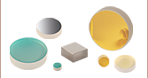
- Operating Wavelength Ranges Covering 550 nm to 1300 nm
- Transmission >80% for Low-Intensity Spectra Detection
- 30 GHz Free Spectral Range
- 5 mm Plano-Concave Cavity Mirror Separation
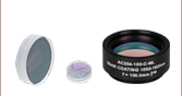
FPQFA-5
Wavelength Range: 550 - 845 nm
Application Idea
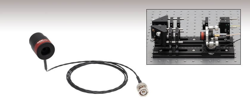
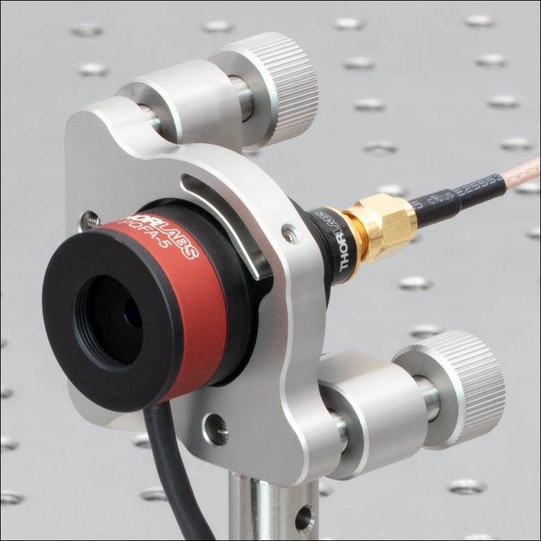
The FPQFA filters can be aligned using a setup built on XT66SD rails and 30 mm cage components. The filter, collimating fiber output lens, focusing lens, and mirrors are kept centered over the optical axis during adjustments. See the Alignment Guide tab for details.


Please Wait

Click to Enlarge
Diagram of the Fabry-Perot Filter (See Item # PA44M3K for details on the Ring Piezoelectric Transducer)
Click to Enlarge
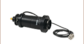
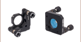
The filters can be mounted in standard Ø1" kinematic mounts like the POLARIS-K1E shown here. A SM05-threaded mounted photodiode (Item # SM05PD2A) is attached to the filter's exit port for measurements up to 1100 nm (photodiode sold separately).
Features
- Operating Wavelength Range from 550 nm - 845 nm or 845 nm - 1300 nm
- Spectral Characterization of Quantum Emitters
- Free Spectral Range (FSR) of 30 GHz
- Transmission >80% for Low-Intensity Spectra Detection
- Finesse >300
- Resolution <100 MHz
- 5 mm Plano-Concave Cavity Mirror Separation
Thorlabs' FPQFA series Tunable Narrow Bandpass Fabry-Perot Filters are ideal for filtering low-light emission spectra over a narrow wavelength range of about 0.1 nm (for a 1 μm wavelength laser) or free spectral range (FSR) of 30 GHz. The Fabry-Perot filters are based on a non-confocal cavity composed of two high reflectivity mirrors, one planar and one spherical concave. The specific frequency transmitted by the cavity can be tuned by adjusting the length of the mirror separation using a piezoelectric transducer, as shown in the diagram to the right. The filters have optical coatings for wavelength ranges from 550 - 845 nm (Item # FPQFA-5) and 845 nm - 1300 nm (Item # FPQFA-8), which are typical ranges for the photoluminescence spectra of Si1 and NV2 centers in diamond and InGaAs quantum dots3. The filter's >80% transmission, 30 GHz FSR, and <100 MHz resolution allow for the investigation of the spectral fine-structures of these low-light quantum emitters.
The FPQFA series filters do not include additional accessories such as a detector, allowing flexibility to customize the use of the filters according to application. The filters can be used to select a part of the incoming light's spectrum, given by the Lorentzian-shaped transmittance characteristics, and use the spectrally filtered light down-stream in an optical system. Or the filters can be operated as scanning devices similar to the SA series FP interferometers, where the transmitted light is immediately measured using a photodiode, amplified by a transimpedance amplifier, and then displayed or recorded by an oscilloscope or data acquisition card. See the Applications tab for examples. Several detector options are available from Thorlabs such as the SM05PD series mounted photodiodes, which can be attached to the filter's SM05-threaded exit port, or external detectors such as the DET series biased detectors, PDA series amplified detectors, or the APD series avalanche detectors.
Click to Enlarge
Click Here for Data
The Fabry-Perot filter transmits fundamental resonance modes at 30 GHz FSR and suppresses light off-resonance typically above -30 dB, not including higher order modes. The higher order modes to the right of the fundamental peaks are highly suppressed, but still transmitted in this measurement; their magnitudes depend strongly on the quality of the mode-matching.
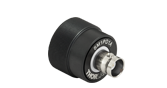
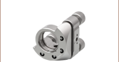
The filter's compact outer aluminum housing is 32 mm long with SM05-threaded entry and exit ports. The cavity mirrors are separated by 5 mm and are made of UV fused silica in a thermally insulating housing to eliminate misalignment due to temperature fluctuations. Each filter has a cable terminated with a BNC connector for controlling the piezo. A focus alignment groove on the housing indicates the position of the plane mirror of the Fabry-Perot cavity. We recommend mounting the filter in a stable Ø1" kinematic mirror mount such as the POLARIS-K1E or KS1 mount. The face of the kinematic mount coincides with the focus alignment groove as shown in the photo above.
Alignment
The filter's plano-concave cavity design can achieve higher performance (optimal finesse, resolution, and transmission) with smaller mirror distances (large FSR) than a confocal cavity. For instance, the filters have >80% on-resonance transmission and are capable of suppressing light typically above -30 dB, as shown in the graph to the right. The on-resonance peaks are separated by the free spectral range (FSR) of 30 GHz, which is given by FSR = c/2d for the cavity length d = 5 mm.
However, the alignment of the plano-concave cavity is more sensitive than that of the confocal cavity as used in the SA series FP interferometers. There is a higher requirement on the matching between the illuminating mode and the fundamental mode supported by the cavity. If the mode illuminating the cavity does not match well with the fundamental cavity mode, higher order cavity modes will be excited, reducing the transmission. The illuminating mode must match in terms of mode waist size, angle, radial and longitudinal position. Follow the steps in the Alignment Guide tab for proper alignment.
Controllers
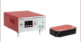
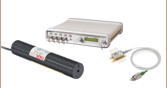
For filtering applications, where a specific frequency is selected and locked on resonance, a high power amplifier, such as the MDT694B Open-Loop Piezo Controller or BPA100 High-Voltage Piezo Amplifier, combined with a signal generator may be needed to use the filters in a high-speed, closed-loop, control system. For scanning applications, which typically don't require as high a power requirement, the Fabry-Perot filters can be used with the SA201B controller. This controller generates a sawtooth or triangle wave voltage required to repetitively scan the length of the Fabry-Perot cavity to sweep through one FSR of the filter, and houses a transimpedance amplifier that can be used to amplify the output of a photodiode detector, which measures the intensity of the light transmitted through the Fabry-Perot cavity. The controller also provides a trigger signal to the oscilloscope, which allows the oscilloscope to easily trigger at the beginning of the scan, or at a user adjustable location along the scan.
| Item # | Wavelength Range | Mirror Substrate | Free Spectral Range | Finesse | Resolution | On-Resonance Transmission | Extinctiona | Cavity Length | Piezo Voltage | Voltage for 1 FSRb |
Electric Impedance |
|---|---|---|---|---|---|---|---|---|---|---|---|
| FPQFA-5 | 550 - 845 nm | UV Fused Silica | 30 GHz | >300 | <100 MHz | >80% | Typ. 30 dB | 5 mm | 0 to 150 V | ≤22×(λ/845) V | 2.2 µF |
| FPQFA-8 | 845 - 1300 nm |
References
- Lindner, S. et al. Strongly Inhomogeneous Distribution of Spectral Properties of Silicon-Vacancy Color Centers in Nanodiamonds. New J. Phys. 2018, 20, 115002.
- Savvin, A., Dormidonov, A., Smetanina, E. et al. NV– Diamond Laser. Nat Commun 12, 7118 (2021).
- Dey, A.B., Sanyal, M.K., Farrer, I. et al. Correlating Photoluminescence and Structural Properties of Uncapped and GaAs-Capped Epitaxial InGaAs Quantum Dots. Sci Rep 8, 7514 (2018).
The sections below outline how to align our Fabry-Perot Filters. Use the following links to jump to a specific section:
- General Instructions
- Beam Waist and Lens Recommendation
- Example Setup to Couple a Collimated Beam into the Fabry-Perot Filter
- Optimizing Alignment

Click to Enlarge
Figure 1: The plane mirror face position in the FP filter is indicated by a groove on the instrument body.
General Instructions
To get started aligning Thorlabs tunable Fabry-Perot filters, mount the instrument in one of Thorlabs highly stable and lockable Ø1" kinematic mirror mounts such as the POLARIS-K1E or KS1 mounts, and then select a lens (discussed below) to focus the beam into the filter's cavity. After selecting the proper lens to mode-match the shape of the incident light with the filter's cavity, it is necessary to have enough degrees of freedom in the alignment setup to mode-match the position of the incoming focused beam such that the waist of the beam is aligned with the plane mirror of the cavity. The plane mirror's position is indicated by the focus alignment groove on the housing as shown in Figure 1. There are two recommended basic setups for aligning the beam while scanning the cavity:
One setup uses two steering mirrors placed before the Fabry-Perot filter that is set in a kinematic mount that won't be adjusted or can be locked (initially a slight adjustment might be needed to make sure filter's face is perpendicular to the beam). The first mirror mainly provides control of the position and the second mirror mainly controls the angle of the incident beam, the axial position of the waist is adjusted by moving a focusing lens placed just upstream of the mirrors. An optional beamsplitter placed upstream of the lens may also be used to help establish the correct lens position. Once the waist is correctly positioned at the plane mirror, the reflected beam will be collimated which can be evaluated by looking at the reflection from the beam splitter. Additionally, an aperture set between the lens and mirrors ensures the beam is perpendicular to the flat cavity mirror when the reflected beam from the cavity passes back through the aperture. This setup is useful for using the transmitted beam in down-stream optics for further processing, since the direction of light is set by the fixed cavity.
In another setup, just one steering mirror can be used before a kinematic mounted filter. The steering mirror in this case controls the horizontal and vertical position of the beam in the cavity, while adjusting the tip-tilt of the filter mostly affects the beam's direction in the cavity. This setup is recommended when a detector or camera is placed immediately after the filter, since the transmitted beam will change direction during alignment. As with the previous setup, the lens should be placed before the mirror and such that the incident beam's waist coincides with the focus alignment groove of the filter's housing.
An example setup using two mirrors to align the filter can be found below. Please see the manual for additional details on these alignment methods.

Click to Enlarge
Click Here for Data
Figure 2: The mode waist values at the flat mirror that are supported by the FPQFA filter cavities are plotted from Equation (1) as a function of wavelength. Optics downstream of the filter see an effective waist size.

Click to Enlarge
Click Here for Data
Figure 3: Optics downstream of the filter see a shifted waist position relative to the actual waist on the flat mirror (positive values are positions after the flat mirror).
Beam Waist Calculation for Plano-Concave Cavity
The plano-concave cavity supports a fundamental mode whose beam radius or waist ωcav is on the flat mirror given by

where d, R, and λ are the cavity length, radius of curvature of the spherical mirror, and wavelength of the beam. For the FPQFA filter cavities, d = 5 mm and R = 250 mm. The waist values supported by this cavity geometry are plotted in Figure 2. Note that as the beam is transmitted through the cavity the waist size and waist position are shifted slightly due to refraction through the spherical mirror, such that optics downstream of the filter see an effective waist size and position. The effective waist sizes are plotted along with their real mode waist values in Figure 2, and the shifted positions of the effective waist after the flat mirror are plotted in Figure 3.
Lens Recommendations for a Free-Space Beam
A free-space beam with a measured waist ω0inc incident on a lens with focal length f will be focused to a radius

where z0inc = πw02/λ is the Rayleigh range of the Gaussian beam. The Rayleigh range is the distance from the lens the waist ω0inc of the beam has increased by a factor of √2. The lens should be placed at a distance
away from the focus alignment groove on the housing, see Figure 5. For z0inc >> f , Equation (3) reduces to D = f and Equation (2) reduces to

so that the ωcav values found from Equation (1) and the measured incident beam waist ω0inc at the lens determine the required focal length of the lens. For example a collimated beam entering the lens with ω0inc = 0.56 mm and requiring ωcav = 84 µm at λ = 633 nm, gives a focal length of f = 233 mm. For the same incident beam radius to mode-match a cavity waist of ωcav = 120 µm at λ = 1300 nm, a focal length of f = 163 mm is needed. Lenses with focal lengths of f = 250 mm in the first case, and f = 150 mm or 175 mm in the latter
example would be reasonable choices. If the setup cannot accommodate a short focal length lens due to space constraints, increasing the
incident beam waist ω0inc will also increase the required focal length.

Click to Enlarge
Figure 4: Diagram of the cavity geometry which determines the fundamental mode-shape of the beam with waist ωcav aligned to the plane mirror.

Click to Enlarge
Figure 5: Schematic showing the beam waist ω0inc incident on the lens focusing the beam to the supported ωcav beam waist at a distance D.
h
Example Setup to Couple a Collimated Beam into a Fabry-Perot Filter

Click to Enlarge
The Fabry-Perot filter can be aligned using a setup which consists of 30 mm cage system and dovetail compatible mounts secured on two 66 mm rails.
| Fabry-Perot Alignment Setup Parts List | |||||
|---|---|---|---|---|---|
| Item # | Qty. | Description | Item # | Qty. | Description |
| FPQFA-5a | 1 | Tunable Fabry-Perot Filter, 550 - 845 nm | RCA1 | 6 | SM1-Threaded 30 mm Cage Plate for 66 mm Rails |
| SM05PD2A | 1 | Mounted Silicon Photodiode, 200-1100 nm | AD12F | 1 | SM1-Threaded Adapter for Ø12 mm, ≥0.35" (8.9 mm) Long Cylindrical Components |
| CA2912 | 1 | SMA Coaxial Cable | 1 | 633 nm, f=6.01 mm, NA=0.28, FC/APC Triplet Collimator | |
| 1 | Polaris® Ø1" Mirror Mount, 3 Adjusters | KCB1c | 2 | Right-Angle Kinematic Mirror Mount with Tapped Cage Rod Holes | |
| XT66P2b | 1 | Rail Carriage for 66 mm Rails | RS05P8E | 1 | Ø1" Pedestal Pillar Post, 8-32 Taps, L = 0.5" |
| XT66SD-250 | 2 | 66 mm Single Dovetail Rail, L = 250 mm | RS4M | 1 | Ø25.0 mm Post Spacer, Thickness = 4 mm |
| SPT1CT | 1 | Coarse ±1 mm XY Thick Slip Plate Positioner | 1 | Single Mode Patch Cable, 633 - 780 nm, FC/APC, 1 m Long | |
| LA1461-B-ML | 1 | Ø1" N-BK7 Plano-Convex Lens, SM1-Threaded Mount, f = 250 mm, ARC: 350-700 nm | |||
| SD1b | 1 | 1/4" (M6) to #8 (M4) Counterbore Adapter Ring | ER2 | 6 | Cage Assembly Rod, 2" Long, Ø6 mm |
The photo above shows a setup to mode-match a beam exiting an optical fiber to the Fabry-Perot filter. The beam exiting an optical fiber will be quickly diverging and requires a collimating lens, such as the TC06APC-633 Triplet Fiber Optic Collimator, to first collimate the beam. The desired waist at the filter can then be achieved by placing the LA1461-B-ML focusing lens after the collimator and adjusting the distance between the lens and the filter. The filter, focusing lens, and collimator are mounted on XT66SD-250 rails for consistent alignment through the system when adjusting their distances. The SPT1CT slip plate positioner provides coarse x-y adjustment to initially center the beam on the focusing lens after exiting the fiber through the TC06APC-633 collimator. The two KCB1 right-angle mirrors, which are mounted to the rails using two RCA1 plates each for extra stability, then provide adjustment of the position and angle into the filter. The Polaris-K1E mount provides stability and additional degrees of freedom for alignment. Finally, a SM05PD2A photodiode is attached to the filter to detect the beam's transmission. Alternative setups might include a beamsplitter and external photodetector before the filter to aid in alignment or after the filter depending on the application.
Optimizing Alignment
For initially roughly aligning the beam, the optics should be set at the same height as the beam. It is ideal to place the mirrors with their faces at a 45° degree angle for 90° beam deflections from each mirror. Once the beam is centered on the filter's aperture, place the lens at the appropriate position ensuring the beam is centered on the lens to minimize deflection. Check that the beam is still centered on all the optics and adjust accordingly. The SM05A7 alignment disk can be attached to the SM05-threaded entry port of filter to initially help center the beam. Connect the photodiode or detector output to an oscilloscope and turn on the piezo ramp signal, such as the output from the SA201B Fabry-Perot controller box or signal generator and amplifier, and start scanning the length of the cavity with the piezoelectric actuator (set the amplitude at a high enough voltage to ensure that more than 1 peak is displayed - see the manual section 4.5 for details). A subtle transmission signal can be observed as the cavity length is resonant with the wavelength of the light beam. The alignment can then be optimized to enhance the mode-matching and increase the transmission signal, see figures below. If no signal is detected at this point, it might be necessary to check the coarse alignment.
While scanning the cavity and carefully observing the signal on an oscilloscope, optimize the alignment of the two steering mirrors by walking the beam as follows: On the mirror furthest from the cavity turn the horizontal axis knob a small amount in the clockwise direction and then optimize the transmitted power using the horizontal axis on the closest mirror. If the power improved, return to the horizontal axis on the first mirror and turn it again in the clockwise direction and repeat. If the power is worse than when it started, return to the first mirror and turn the knob counterclockwise. Optimize the power again of the horizontal axis on the closest mirror and repeat. Continue until the power is optimized using only the horizontal axes. Repeat this procedure using the vertical axes. Iterate on both directions and until the transmission peaks are optimized. At this point there should be very little power coupling into the higher order modes. If the mode-matching is still not satisfactory, it may be necessary to translate the lens axially or change the focal length.
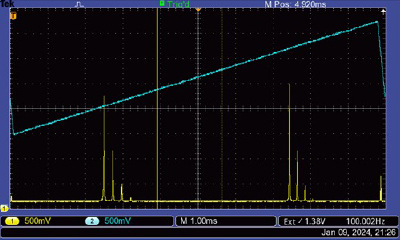
The figures below show the oscilloscope display of the ramp signal trace in blue and the photodiode/detector output trace from the Fabry-Perot filter in yellow as the alignment improves the mode-matching of the beam to the cavity:
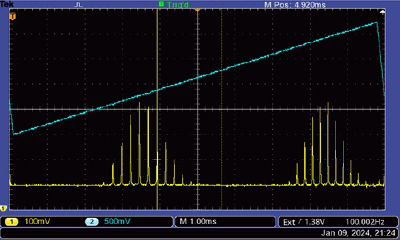
After a first iteration the transmission improves along with many higher order modes, further optimization is required.
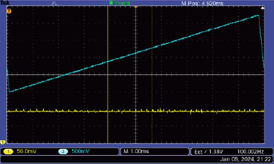
After rough alignment many small peaks begin to emerge.
A second iteration increases the fundamental resonance mode and the higher order modes begin to suppress.
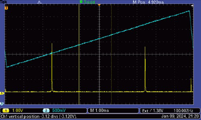
Here, mode-matching is achieved and the higher order modes are mostly decoupled. Note the change in scale from 500 mV to 1.00 V of the yellow trace.
Two major modes of operation for using the FPQFA Fabry-Perot filters are considered in the diagrams below:

Click to Enlarge
The filters can be used to scan frequencies and measure the light's spectral properties. Part of the transmitted signal from the filter is immediately measured using the reflected light from a beamsplitter and sent to a photodetector, then displayed on an oscilloscope. The transmitted light that passes through the beamsplitter can be used in downstream optics depending on application. An amplified triangle wave produced by a signal generator is used to drive the filter's piezo. The signal generator's trigger signal is sent to the oscilloscope to stay in phase with the transmitted signal.

Click to Enlarge
The filters can be used to select specific frequencies in a closed-loop feedback system, where the spectrally filtered light is transmitted to downstream optics for further use. Here the transmitted resonance signal from the cavity is picked off from a beamsplitter for detection and then sent to a Proportional Integral Derivative (PID) regulator, which is amplified to continually drive the cavity back on resonance.
| Posted Comments: | |
Ozan Arı
(posted 2024-04-18 20:27:38.217) Can we use this device as a spectrometer to measure transmittance from a nano-cavity with 5-10 nm FSR and a few GHz FWHM, such as wavelength vs transmitted intensity with 100 MHz resolution? acanales
(posted 2024-04-19 07:01:52.0) Thank you for contacting Thorlabs! The FPQFA is not a spectrometer but rather a very narrow bandpass filter (100 MHz) with a tunable transmitted wavelength window. It can be used to measure spectral properties like linewidth but not to obtain wavelength information. Instead, we can suggest an OSA30x with a resolution of 1.9 GHz. Unfortunately, 100 MHz is too high a resolution for our spectrometers. |