 Products Home / Optomechanical Components / Optomechanical Mounts / Component Mounts / Bi-Telecentric Lens Clamps
Bi-Telecentric Lens Clamps
- Secure 0.128X or 0.243X Bi-Telecentric Lenses
- Hinged Clamps on Each End Secure the Lenses
- Allows Either Vertical or Horizontal Mounting
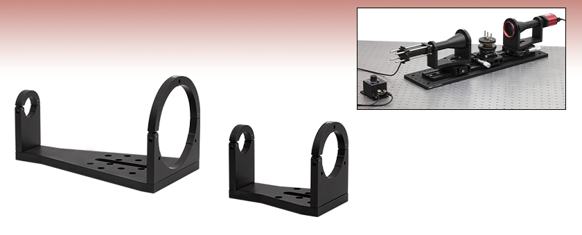
MVBTC45
Mounting Clamp for the MVBT2313 0.128X Bi-Telecentric Lens
MVBTC25
Mounting Clamp for the MVBT2324 0.243X Bi-Telecentric Lens
Application Idea
Two MVBT2324 Bi-Telecentric Lenses are mounted with the MVBTC25/M Lens Clamps in an inspection system used for imaging samples, such as the screws shown here.


Please Wait
Click to Enlarge
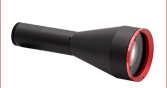
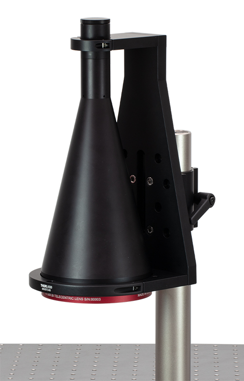
The MVBT2313 lens is mounted vertically with the MVBTC45 clamp.
Features
- Accommodates 0.128X or 0.243X Bi-Telecentric Lenses
- Hinged Clamps on Each End Secure the Lenses
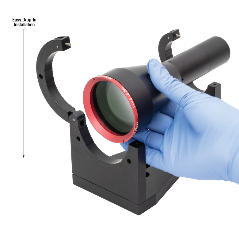
- Clamp Base Features Counterbored Slot and Mounting Holes
- Easy Drop-in Installation and Removal of Bi-Telecentric Lenses
Thorlabs' Bi-Telecentric Lens Mounting Clamps allow the MVBT2313 or MVBT2324 Bi-Telecentric Lenses to be easily mounted and removed via the double open-arm design. The MVBTC45(/M) clamp is designed to mount the MVBT2313 lens, while the MVBTC25(/M) clamp is designed to mount the MVBT2324 lens. The front and back clamping arms on both mounts assist with easy drop-in installation (see the image on the far right for details). Additionally, the mounts allow the compatible lenses to be mounted in a horizontal or vertical orientation. Please see the Machine Vision Application tab for an example of how these clamps can be used to image samples.
The inner diameter of the MVBTC45(/M) is Ø4.50" (Ø114.3 mm) at its largest point, while the inner diameter of the MVBTC25(/M) at its largest point is Ø2.50" (Ø63.5 mm). Both lens clamps have an inner diameter of Ø1.20" (Ø30.5 mm) at their smallest point. Both arms on the clamps are secured via a 5/64" (2.0 mm) hex captive locking screw. A torque of 3 in-lbs (0.34 Nm) is recommended to apply to the captive locking screws that secure the lens in the clamp.
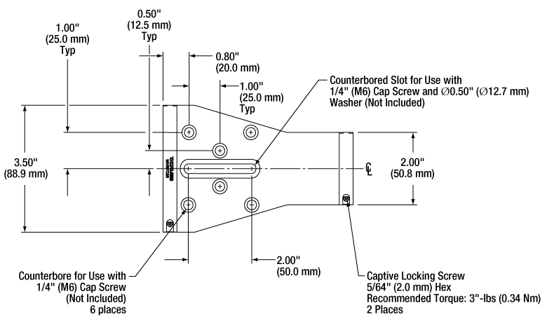
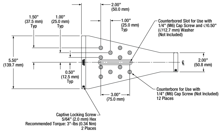
Each clamp features a counterbored slot that is 3" (75.0 mm) long for the MVBTC45(/M) and 2" (50.0 mm) long for the MVBTC25(/M), as well as counterbored holes for use with 1/4" (M6) cap screws (twelve for the MVBTC45(/M) and six for the MVBTC25(/M)). This enables the clamps to be mounted to a variety of breadboards, posts, rail carriers, and rail accessories, in either a horizontal orientation as shown above or a vertical orientation as shown to the right.
Click to Enlarge
Mounting Hole Pattern for the MVBTC25(/M) Clamp
The dimensions for the metric clamp are shown in parentheses.
Click to Enlarge
Mounting Hole Pattern for the MVBTC45(/M) Clamp
The dimensions for the metric clamp are shown in parentheses.
Application
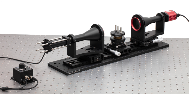
A basic machine vision setup, using two bi-telecentric lenses to inspect the quality of several screws is illustrated below. Two MVBT2324 0.243x Bi-Telecentric Lenses are mounted in MVBTC25/M 0.243x mounting clamps for easy integration into the inspection system. Light from an LEDBW1 diffuse backlight LED is collimated by one MVBT2324 lens to provide uniform profile illumination. A CS505MU Kiralux 5.0 MP Monochrome CMOS Camera mounted on the other lens captures images of samples. Two XR25P/M linear translation stages and an LJ750/M compact lab jack allow fine adjustment in 3 axes. Additionally, the lab jack top platform can be rotated 360° and locked in place.
This setup can be easily re-configured to suit a variety of inspection needs. The MVBT2324 lenses can be replaced with higher or lower magnification bi-telecentric lenses, a custom asphere-collimated LED can provide an alternate method of illumination, and motorized stages can replace the manual ones. It can also be designed with the optical axis oriented vertically, so flat parts such as gaskets, stampings, and printed circuit boards (PCBs) can be laid flat on a sample holder. For a fully automated inspection and measurement solution, please see Thorlabs' VideoMic® multisensory video measuring system.
Click to Enlarge
Two MVBT2324 0.243x Bi-Telecentric Lenses are mounted with MVBTC25/M 0.243x Bi-Telecentric Lens Clamps in an inspection system. This setup can be used for imaging samples, such as the screws pictured here.
Click to Enlarge
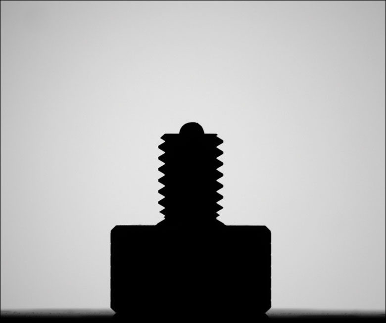
Two M6 Screws Imaged with the Inspection System
Imperial Product List
Metric Product List
Telecentric Lenses
Telecentric lenses are designed to have a constant magnification regardless of the object's distance or location in the field of view. This attribute is ideal for many machine vision measurement applications, as measurements of an object's dimensions will be independent of where it is located.
Types of Telecentric Lenses
In order to achieve a telecentric lens design, all of the chief rays (rays from an off-axis point that pass through the center of the aperture stop) have to be parallel to the optical axis in either image space or object space, or both.
For an object space telecentric lens, the chief rays will be parallel to the optical axis on the object's side of the lens (object space). This is accomplished by setting the aperture stop at the front focal plane of the lens, which results in an entrance pupil at infinity. Since chief rays are directed towards the center of the entrance pupil, the chief rays on the object side of the lens will be parallel to the optical axis. An example of an object space telecentric lens is shown in Figure 119A.
For an image space telecentric lens, the chief rays will be parallel to the optical axis on the image's side of the lens (image space). This is accomplished by setting the aperture stop at the back focal plane of the lens, which results in an exit pupil at infinity. Since the chief rays must pass through the center of the exit pupil, the chief rays on the image side of the lens must be parallel to the optical axis. An example of an image space telecentric lens is shown in Figure 119B.

Click to Enlarge
Figure 119A A ray trace through an idealized object space telecentric lens system. Note that the chief rays (the center ray of each color) are parallel to the optical axis in object space, but in image space, the chief rays form an angle with the optical axis.

Click to Enlarge
Figure 119B A ray trace through an idealized image space telecentric lens system. Note that the chief rays (the center ray of each color) are parallel to the optical axis in image space, but in object space, the chief rays form an angle with the optical axis.
For a double telecentric, or bi-telecentric, lens, the front and back focal planes are made to overlap so that the aperture stop is located where both the entrance and exit pupils are at infinity. In a bi-telecentric lens, neither the image or object location will affect the magnification. Thorlabs' telecentric lenses are all bi-telecentric designs. Figure 119C shows an example ray trace through a bi-telecentric lens and illustrates how the chief rays pass through the system.

Click to Enlarge
Figure 119C A ray trace through an idealized bi-telecentric lens system. Note that the chief rays (the center ray of each color) are parallel to the optical axis in both image and object space, which means that the magnification will remain constant regardless of object distance.
Conventional Lenses
In conventional lenses, the entrance and exit pupils are not located at infinity, so the chief rays will not be parallel to the optical axis. In this case, the magnification of the object depends on its distance from the lens and its position in the field of view. Figure 119D shows an example ray trace through a conventional camera lens; notice how the chief rays are angled with respect to the optical axis in both image and object space. Note that both Figures 119C and 119D feature the same lens design; only the aperture stop location was varied to shift the bi-telecentric system to a non-telecentric one.

Click to Enlarge
Figure 119D A ray trace through an idealized conventional camera lens system. Note that the chief rays (the center ray of each color) are not parallel to the optical axis in both image and object space, which means that the magnification will vary with object distance.
Example Images
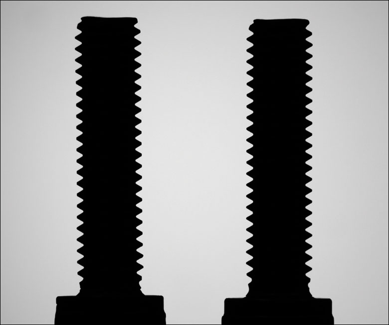
Figures 119E and 119F show photographs taken with a bi-telecentric lens and a standard camera lens, respectively. With the telecentric imaging system, the height of the two screws appears to be the same, even though the object planes are separated by approximately 45 mm along the optical axis. With the conventional imaging system, the two screws appear to be different heights, which could result in inaccurate dimensional measurements. A machine vision system using a bi-telecentric lens can offer advantages for dimensional metrology. For example, these lenses can be integrated into our Multi-Sensor Video Measurement Machines.

Click to Enlarge
Figure 119E An image of two identical 8-32 cap screws imaged with our previous generation MVTC23013 0.128X Telecentric Lens. Although the screws appear to be the same size and in the same object plane, they are actually separated by a distance of approximately 45 mm along the optical axis.

Click to Enlarge
Figure 119F The same two screws photographed with our previous-generation MVL7000 conventional zoom lens. The MVL7002 lens provides similar performance. In this image, the perspective error due to the separation of the screws would lead to incorrect height measurements.
| Posted Comments: | |
| No Comments Posted |