N-BK7 Plano-Concave Lenses, Uncoated
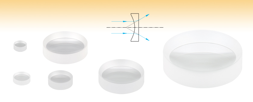
- Negative Focal Length Used to Diverge Collimated Beams
- Zemax Files Available
- Wavelength Range: 350 nm - 2.0 µm
LC1975
(Ø6 mm)
LC1906
(Ø9 mm)
LC1054
(Ø1/2")
LC1259
(Ø25 mm)
LC1715
(Ø1")
LC1315
(Ø2")

Please Wait
| Common Specifications | |
|---|---|
| Lens Shape | Plano-Concave |
| Substrate Material | N-BK7 (Grade A)a |
| Wavelength Range | 350 nm - 2.0 µm |
| Diameters Available | 6 mm, 9 mm, 1/2", 25 mm, 1", or 2" |
| Diameter Tolerance | +0.0/-0.1 mm |
| Thickness Tolerance | ±0.1 mm |
| Focal Length Tolerance | ±1% |
| Design Wavelength | 587.6 nm (Except Ø25 mm Lenses) 632.8 nm (Ø25 mm Lenses) |
| Index of Refraction @ 633 nm |
1.515 |
| Surface Quality | 40-20 Scratch-Dig |
| Surface Flatness (Plano Side) |
λ/2 |
| Spherical Surface Powerb (Concave Side) |
3λ/2 |
| Surface Irregularity (Peak to Valley) |
λ/4 |
| Abbe Number | vd = 64.17 |
| Centration | <3 arcmin |
| Clear Aperture | >90% of Diameter |
| Click on the red Document icon next to the item numbers below to access the Zemax file download. Our entire Zemax Catalog is also available. |
Features
- Material: N-BK7
- Wavelength Range: 350 nm - 2.0 μm (Uncoated)
- Choose from 6 Diameters: Ø6 mm, Ø9 mm, Ø1/2" (Ø12.7 mm), Ø25 mm,
Ø1" (Ø25.4 mm), or Ø2" (Ø50.8 mm) - Offers Excellent Transmission Throughout the Visible and Near Infrared
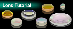
These Plano-Concave lenses are fabricated from RoHS-compliant N-BK7 glass. N-BK7 is one of the most common types of optical glass used for high quality optical components. It is typically chosen whenever the additional benefits of UV fused silica (i.e., good transmission further into the UV and a lower coefficient of thermal expansion) are not necessary. However, for particularly harsh environments where the optic will be exposed to alkalis and acids, consider our N-SF11 plano-concave lenses. Since the Abbe Number of N-SF11 (25.76) is lower than that for N-BK7 (64.17), lenses fabricated from N-SF11 will exhibit higher dispersion than those fabricated from N-BK7.
These lenses, like all plano-concave lenses, have negative focal lengths and can be used to diverge collimated beams. In this case, the curved surface of the lens should face the source to minimize spherical aberration. In addition, they can be employed to offset the effects of spherical aberration caused by other lenses in an optical system.
N-BK7 lens kits are also available. Please click here for information.
| N-BK7 Plano-Concave Lens Selection Guide | |
|---|---|
| Unmounted Lenses | Mounted Lenses |
| Uncoated | Uncoated |
| A Coating (350 - 700 nm) | A Coating (350 - 700 nm) |
| B Coating (650 - 1050 nm) | B Coating (650 - 1050 nm) |
| C Coating (1050 - 1700 nm) | C Coating (1050 - 1700 nm) |
| Quick Links to Other Spherical Singlets | ||||||
|---|---|---|---|---|---|---|
| Plano-Convex | Bi-Convex | Best Form | Plano-Concave | Bi-Concave | Positive Meniscus | Negative Meniscus |
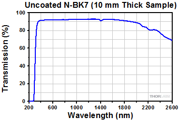
Below is the transmission curve for N-BK7, a RoHS-compliant form of BK7. Total Transmission is shown for a 10 mm thick, uncoated sample and includes surface reflections.
Click to Enlarge
Click Here for Raw Data
| N-BK7 Plano-Concave Lens Selection Guide | |
|---|---|
| Unmounted Lenses | Mounted Lenses |
| Uncoated | Uncoated |
| A Coating (350 - 700 nm) | A Coating (350 - 700 nm) |
| B Coating (650 - 1050 nm) | B Coating (650 - 1050 nm) |
| C Coating (1050 - 1700 nm) | C Coating (1050 - 1700 nm) |
The lenses sold on this page are also available with broadband antireflective coatings, the reflectance traces of which are shown in the graph below.
These high-performance multilayer AR coatings have an average reflectance of less than 0.5% (per surface) across the specified wavelength ranges and provide good performance for angles of incidence (AOI) between 0° and 30° (0.5 NA). The plot shown below indicates the performance of the standard coatings in this family as a function of wavelength. Broadband coatings have a typical absorption of 0.25%, which is not shown in the reflectance plots.

 Click to Enlarge
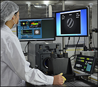
A Thorlabs technician measuring the irregularity of one of our singlets using a Zygo GPI-XP/D Interferometer.
Introduction
Thorlabs has a series of quality control procedures in order to ensure our singlets meet our standards and specifications. This starts with in-process inspections of the lens’ imaging capabilities and ends with a final inspection of surface quality and dimensions. Specifications for particular products can be found in their linked documentation by clicking the ![]() symbol. This tab will take you through the general process used to check for quality.
symbol. This tab will take you through the general process used to check for quality.
Singlet Quality Practices
In-process inspection begins once the singlet has been shaped to specifications. Focal length, surface irregularity, and surface power are checked, following sampling plan Level VI given in MIL-PRF-13830B (see below). These three specifications are imperative for proper imaging. Surface irregularity of parts is kept to below either a quarter wavelength or a half wavelength at 633 nm, depending on the material of the singlet. Below is a graph of over 200 batches of singlets with irregularity data of both their front and back sides.
At this point, some uncoated singlets will proceed to final inspection, while others will receive an antireflective (AR) coating. The application of optical coatings has its own in-process inspections. To ensure the AR coating is applied properly, we verify both reflectance and transmission performance by scanning witness pieces using spectrophotometry; the material of these 2 mm thick witness samples matches the other parts in the run. For reflectance verification, we use at least one witness sample for each coating run. Transmitting optics receive two AR coatings, one on each surface, so for the verification of transmission, we use one witness sample that is also coated on both of its sides. Large runs use multiple witness samples to ensure the uniformity across the deposition chamber. By testing coating performance during every run, variance over time is kept low. To see how coatings vary, see the table below.
Final inspection of both uncoated and AR-coated singlets includes a batch check of diameter and thickness and a 100% visual check to ensure that the surface quality, chamfer, and clear aperture meet our published specifications. While surface quality is cosmetic to a degree, scratches, digs, and other inclusions in the surface of a part can increase the chances of damage to the singlet when used with high-power sources. These inspections are done in a clean, dark room under lighting that meets the requirements of MIL-PRF-13830B. Inspection under a single light source in a dark room allows for inconsistencies in the glass to be located without being obscured by glare or reflections.
MIL-PRF-13830B: Performance Specifications for Optical Components
MIL-PRF-13830B is a document created by the U.S. Army Armament Research, Development and Engineering Center's Defense Quality and Standardization Office for the specifications covering how finished optical components should be manufactured, assembled, and inspected. While primarily for use in letting the military dictate how products they use can be incorporated into their equipment, these standards have been adopted by many optics manufacturers. To download a copy of the full document,
| -A Coating 350 nm to 700 nm |
-B Coating 650 nm to 1050 nm |
-C Coating 1050 nm to 1700 nm |
Singlet Irregularity |
||
| Coating Variance: Transmission |
 Click to Enlarge |
 Click to Enlarge |
 Click to Enlarge |
 Click to Enlarge |
|
| Coating Variance: Reflectance |
 Click to Enlarge |
 Click to Enlarge |
 Click to Enlarge |
| Recommended Mounting Options for Thorlabs Lenses | ||
|---|---|---|
| Item # | Mounts for Ø2 mm to Ø10 mm Optics | |
| Imperial | Metric | |
| (Various) | Fixed Lens Mounts and Mini-Series Fixed Lens Mounts for Small Optics, Ø5 mm to Ø10 mm | |
| (Various) | Small Optic Adapters for Use with Standard Fixed Lens Mounts, Ø2 mm to Ø10 mm | |
| Item # | Mounts for Ø1/2" (Ø12.7 mm) Optics | |
| Imperial | Metric | |
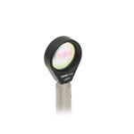
| LMR05 | LMR05/M | Fixed Lens Mount for Ø1/2" Optics |
| MLH05 | MLH05/M | Mini-Series Fixed Lens Mount for Ø1/2" Optics |
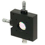
| LM05XY | LM05XY/M | Translating Lens Mount for Ø1/2" Optics |
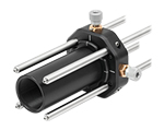
| SCP05 | 16 mm Cage System, XY Translation Mount for Ø1/2" Optics | |
| (Various) | Ø1/2" Lens Tubes, Optional SM05RRC Retaining Ring for High-Curvature Lenses (See Below) |
|
| Item # | Mounts for Ø1" (Ø25.4 mm) Optics | |
| Imperial | Metric | |
| LMR1 | LMR1/M | Fixed Lens Mount for Ø1" Optics |
| LM1XY | LM1XY/M | Translating Lens Mount for Ø1" Optics |
| ST1XY-S | ST1XY-S/M | Translating Lens Mount with Micrometer Drives (Other Drives Available) |
| CXY1A | 30 mm Cage System, XY Translation Mount for Ø1" Optics | |
| (Various) | Ø1" Lens Tubes, Optional SM1RRC Retaining Ring for High-Curvature Lenses (See Below) |
|
| Item # | Mount for Ø1.5" Optics | |
| Imperial | Metric | |
| LMR1.5 | LMR1.5/M | Fixed Lens Mount for Ø1.5" Optics |
| (Various) | Ø1.5" Lens Tubes, Optional SM1.5RR Retaining Ring for Ø1.5" Lens Tubes and Mounts |
|
| Item # | Mounts for Ø2" (Ø50.8 mm) Optics | |
| Imperial | Metric | |
| LMR2 | LMR2/M | Fixed Lens Mount for Ø2" Optics |
| LM2XY | LM2XY/M | Translating Lens Mount for Ø2" Optics |
| CXY2 | 60 mm Cage System, XY Translation Mount for Ø2" Optics |
|
| (Various) | Ø2" Lens Tubes, Optional SM2RRC Retaining Ring for High-Curvature Lenses (See Below) |
|
| Item # | Adjustable Optic Mounts | |
| Imperial | Metric | |
| LH1 | LH1/M | Adjustable Mount for Ø0.28" (Ø7.1 mm) to Ø1.80" (Ø45.7 mm) Optics |
| LH2 | LH2/M | Adjustable Mount for Ø0.77" (Ø19.6 mm) to Ø2.28" (Ø57.9 mm) Optics |
| VG100 | VG100/M | Adjustable Clamp for Ø0.5" (Ø13 mm) to Ø3.5" (Ø89 mm) Optics |
| SCL03 | SCL03/M | Self-Centering Mount for Ø0.15" (Ø3.8 mm) to Ø1.77" (Ø45.0 mm) Optics |
| SCL04 | SCL04/M | Self-Centering Mount for Ø0.15" (Ø3.8 mm) to Ø3.00" (Ø76.2 mm) Optics |
| LH160C | LH160C/M | Adjustable Mount for 60 mm Cage Systems, Ø0.50" (Ø13 mm) to Ø2.00" (Ø50.8 mm) Optics |
| SCL60CA | SCL60C/M | Self-Centering Mount for 60 mm Cage Systems, Ø0.15" (Ø3.8 mm) to Ø1.77" (Ø45.0 mm) Optics |
Mounting High-Curvature Optics
Thorlabs' retaining rings are used to secure unmounted optics within lens tubes or optic mounts. These rings are secured in position using a compatible spanner wrench. For flat or low-curvature optics, standard retaining rings manufactured from anodized aluminum are available from Ø5 mm to Ø4". For high-curvature optics, extra-thick retaining rings are available in Ø1/2", Ø1", and Ø2" sizes.
Extra-thick retaining rings offer several features that aid in mounting high-curvature optics such as aspheric lenses, short-focal-length plano-convex lenses, and condenser lenses. As shown in the animation to the right, the guide flange of the spanner wrench will collide with the surface of high-curvature lenses when using a standard retaining ring, potentially scratching the optic. This contact also creates a gap between the spanner wrench and retaining ring, preventing the ring from tightening correctly. Extra-thick retaining rings provide the necessary clearance for the spanner wrench to secure the lens without coming into contact with the optic surface.
| Posted Comments: | |
p.clark
(posted 2013-04-05 12:18:10.543) Suggestion.
It would be nice if 1 inch diameter plano-convex and plano-concave lenses were available in even increments of optical power (say, -4, -3, -2, -1, +1, +2, +3, +4 diopters). That would be focal lengths: -250, -333.33, -500, -1000, +1000, +500, +333.33, +400 mm. Very useful for through-focus studies of cameras, etc., and it would make a nice set, like the old ophthalmic trial lenses. cdaly
(posted 2013-04-18 14:12:00.0) Response from Chris at Thorlabs: We may be able to do some custom focal lengths, but typically these require a minimum order quantity. I will make this suggestion to our optics department and perhaps it can be offered as stock components in the future. I will contact you directly to discuss this further. Laurie
(posted 2009-01-05 09:46:40.0) Response from Laurie at Thorlabs to ali_mos: Thank you for your interest in our plano-concave lenses. Our coated lenses can handle powers of ~100W/cm^2 for CW light and 100 mJ/cm^2 for 10 ns pulses. The uncoated lenses can handle powers of ~2 kW/cm^2 for CW light and 3 J/cm^2 for 10 ns pulsed light. If you have additional questions, please feel free to contact our technical support staff. ali_mos
(posted 2009-01-02 20:00:14.0) I coudnt find the damage threshold of lenses which is very important, where can I find it? technicalmarketing
(posted 2008-02-13 10:38:41.0) Dear Mcneil
I was unable to find the error you mentioned but you are correct. The information for SF11 is as follows: n=1.784720, Vd=25.7566, and Glass Code=785258. Thank you for providing your feedback. dbmcneil
(posted 2008-02-12 18:43:10.0) For SF11, you list the index of refraction as 1.515 and the glass code as 515/642. However, elsewhere, Ive seen the index listed as 1.785 and the glass code as 785/258. Looking at the listed Abbe number of 25.76, we only really have a choice of SF or LaSF glasses, which all have indexes of 1.75 mininum. Thus, I tend to think that your listed data might be in error. |


 Products Home



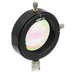
 N-BK7, Uncoated