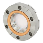
High-Vacuum CF Flange Viewports for Ø1" Windows
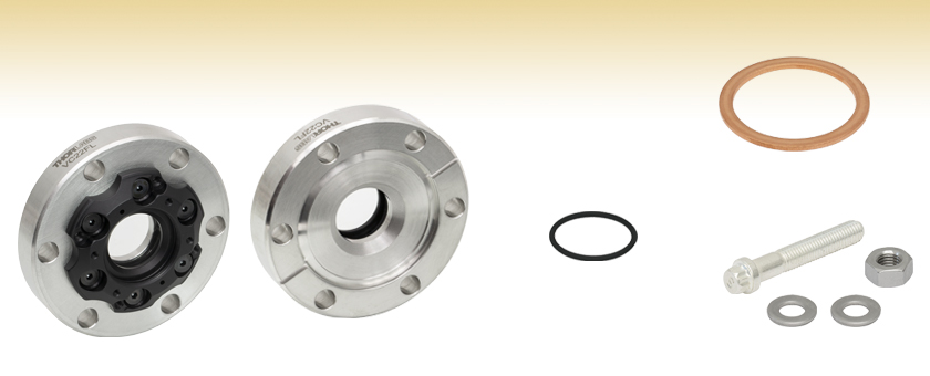
- CF Flange Viewports for High-Vacuum Systems
- Compatible with Ø1" Flat Windows
- Sapphire, CaF2, or UV Fused Silica Windows
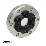
VC224
Ø1" Flat Window Viewport,
Uncoated CaF2 (180 nm - 8 µm)
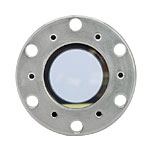
Front
VGA10
Annealed Copper Gaskets,
10 Pack
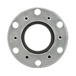
Back
VMH6
Flange Mounting Hardware Pack
(6 Bolts, 6 Nuts, & 12 Washers)
VC22VO
Viton O-Ring

Please Wait
| Common Vacuum Specifications | |
|---|---|
| Vacuum Level | 1 x 10⁻⁸ Torr (Max) |
| Max Temperature | 150 °C |
| Thermal Gradient | 20 °C/min (Max) |
Features
- Vacuum Level: 1 x 10⁻⁸ Torr (Max)
- Bake Temperature: 150 °C (Max)
- Available with One of Three Uncoated Substrates
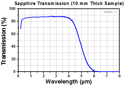
- Sapphire for 200 nm - 4.5 μm
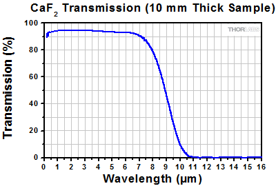
- Calcium Fluoride (CaF2) for 180 nm - 8.0 μm
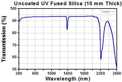
- UV Fused Silica for 185 nm - 2.1 μm
- Flange and Viton O-Ring Also Available Separately
- Flange Mounting Hardware Pack and Copper Gaskets Sold Below
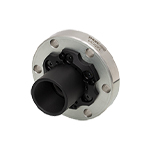
Thorlabs' high-vacuum-compatible Ø2.75" (DN40) CF Flange Viewports for Ø1" Optics are offered with one of three uncoated window substrates: sapphire (200 nm - 4.5 µm), CaF2 (180 nm - 8.0 µm), or UVFS (185 nm - 2.1 µm). Please see the Graphs tab for transmission data. Additionally these viewports are compatible with our selection of stock Ø1" flat windows with thicknesses between 4.9 - 5.15 mm. These flanges are not compatible with wedged windows.
Designed for use at high-vacuum (HV) pressures, Thorlabs' CF viewports utilize Viton O-Ring seals to create an air-tight metal/glass seal, allowing for pressures down to 10-8 Torr. The vacuum windows are interchangeable, enabling the user to swap out vacuum windows mounted in our HV CF flanges. Additionally, CF flanges (viewports without vacuum windows) are also available that are also compatible with our Ø1" windows. Before swapping and attempting to install additional windows, please review the procedure outlined in the Window Installation tab above.
Copper gasket and mounting hardware sets for Ø2.75" CF flanges are also available below. Thorlabs also offers HV CF Flange Viewports for Ø1.5" flat windows and Ø1.5" wedged windows.
| Flange Item # | VC223 | VC225 | VC224 |
|---|---|---|---|
| Window Materiala | Sapphire | Calcium Fluoride | UV Fused Silica |
| Window Diameter (Unmounted) | 1" (25.4 mm) | ||
| Window Thickness (Unmounted) | 0.20" (5.0 mm) | ||
| Clear Apertureb | Ø0.71" (Ø18 mm) | ||
| Transmitted Wavefront Error @ 633 nmc | λ | λ/8 | λ/10 |
| Surface Quality | 60-40 Scratch-Dig | 20-10 Scratch-Dig | |
| Parallelism | <3 arcmin | <10 arcsec | <5 arcsec |
| Replacement Window Item #d | WG31050 | WG51050 | WG41050 |
The graphs below show the transmission of light through uncoated sapphire, calcium fluoride (CaF2), and UV fused silica substrates. Raw data in the Excel format is available by clicking on the links below the graphs.
Click to Enlarge
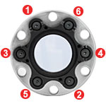
Fig. 5: Order of faceplate screw tightening.
Click to Enlarge
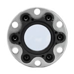
Fig. 4: Viewport with faceplate aligned over screw holes.
Click to Enlarge
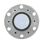
Fig. 3: Viewport with top O-ring placed on window.
Click to Enlarge
Fig. 2: Viewport with window placed on bottom O-ring.
Click to Enlarge
Fig. 1: Viewport with front face removed and O-ring inserted.
Our high-vacuum viewports allow the user to install or swap out windows as they desire, or as experimental conditions demand. Installation of the windows is relatively quick and simple. The following steps describe how to install and change windows in our high-vacuum CF flanges.
Step 1: Inspect the O-ring and seat for pits, scratches, or contamination. Remove any loose debris from the seat using compressed air and then install the O-ring in the seat (see Fig. 1). If necessary, clean the window by following our optics cleaning tutorial.
Step 2: Place the window on top of the O-ring (see Fig. 2) and then place and center the second O-ring on top of the window (see Fig. 3).
Step 3: Set the faceplate on top of the window, lining up the O-ring with the faceplate groove and the six holes in the faceplate with the threaded holes in the flange (see Fig. 4). Do not slide the part across the window surface.
Step 4: Place the six screws in the faceplate holes and use a 5/64" (2.0 mm) hex key to thread them so that they are just making contact with the faceplate.
Step 5: In the order illustrated in Fig. 5, turn each screw a quarter turn, repeating the pattern until the faceplate is tight against the flange.
Insights into CF Vacuum Flanges
Scroll down to read about:
- Working with CF Vacuum Flanges
Click here for more insights into lab practices and equipment.
Working with CF Vacuum Flanges
A vacuum coupling that supports operation at ultra-high-vacuum levels
Damage to the knife edge, an aggressive approach to tightening the bolts, and reusing gaskets can all result in leaky CF vacuum couplings. The techniques demonstrated in this video reduce the risk presented by these factors, which are all related to the limited malleability of the metal gasket. It is important that the knife edges are in pristine condition, since the gasket is not soft enough to fill narrow or abrupt features, such as a nick in a knife edge. An approach of gradually and iteratively tightening the bolts is effective in maintaining a uniform thickness of the gasket around its circumference, while tightening each bolt all at once can result in thickness variations in the gasket that are difficult or impossible to flatten. This is a consequence of the metal gasket’s limited ability to flow and can result in gaps between the gasket and knife edges. Using a new gasket is always recommended. Even a gasket that was only partially compressed during a previous use may not be malleable enough, when reused, to conform to the contours of the knife edges. This is because compression has the effect of strain (work) hardening the metal.
While a leaky vacuum connection can result in time lost to leak checking and re-opening the vacuum system to locate and fix the problem, productive work can also be delayed as a result of broken or malfunctioning components in or attached to the chamber. Due to this, an overview of special considerations for handling and using fiber feedthroughs is also included in this video.
If you would like more information about tips, tricks, and other methods we often use in the lab, we recommend our other Video Insights. In addition, our webinars provide practical and theoretical introductions to our different products.
ConFlat® is a registered trademark of Agilent Technologies, Inc.
| Products Featured During Demonstration | |||
| Optical Fiber Feedthrough | 1/4-Hard Copper Gaskets | Fiber Inspection Scope | Nitrile Gloves |
| UHV Fiber Patch Cable | Solvent Dispenser | Fiber Connector Cleaner | Wipes |
Date of Last Edit: Sept. 21, 2022
| Posted Comments: | |
Jason Hancock
(posted 2023-02-05 06:45:54.963) Hi, great product. I was wondering what are the prospects of developing a similar 1" optical access window for a CF4.5" vacuum fitting? Should be simple enough if the manufacture starts with a blank. Thanks. cdolbashian
(posted 2023-02-17 11:19:22.0) Thank you for reaching out to us with this inquiry Jason. This is something which is potentially feasible for us. I have contacted you directly to discuss your specifications and requirements. For future custom requests, please feel free to contact techsales@thorlabs.com. Demid Sychev
(posted 2022-02-07 19:58:58.823) Hello,
We're thinking about purchasing optical windows for our cryostat. Will it work for mK temperatures? jdelia
(posted 2022-03-07 08:05:22.0) Thank you for contacting Thorlabs. We do not suggest using these products at mK temperatures, as Viton cannot be used below ~ -20 C. I have contacted you directly regarding alternative options Armindo Oliveira
(posted 2019-10-22 10:32:24.2) Hello,
I intend to use VPCH12-FL with a 1'' Germanium window in a waterproof IR camera prototype.
What do you suggest to use as counter flange? YLohia
(posted 2019-10-24 09:51:57.0) Hello, thank you for contacting Thorlabs. The VFA275 would be an appropriate flange mounting adapter for the VPCH12-FL. btyee
(posted 2017-05-12 07:41:16.66) Is there a good option to integrate a lens (plano-convex) with a CF flange? For VPCH12-FL, it seems that most lenses are simply not thick enough at the edges. tfrisch
(posted 2017-05-17 04:40:10.0) Hello, thank you for contacting Thorlabs. Mounting a lens in a conflat is not a common application. Typically the lens would be mounted inside or outside the chamber if necessary. I will contact you directly to discuss mounting solutions such as VFA275. Joseph.E.Roser
(posted 2017-04-06 15:03:08.223) I would also be interested in this product in a double-sided CF flange.
Is it possible to use a thinner window and two o-rings for a vacuum seal on the chamber side and on the faceplate side of the window? tfrisch
(posted 2017-04-19 03:51:21.0) Hello, thank you for contacting Thorlabs. While at low pressures, the pressure differential is the most important quantity, we do not have the necessary equipment to test your unique configuration, and these flanges are designed such that the inside pressure is low and the outside pressure is about 1atm. I will reach out to you to discuss my concerns, but at the very least, there is not an appropriate seat for an O-ring on the reverse side. vittorgd
(posted 2015-03-24 19:18:38.87) What are the part numbers for the actual windows provided in the VPCH312, 412, and 512? jlow
(posted 2015-03-26 11:08:39.0) Response from Jeremy at Thorlabs: The part numbers are WG31050, WG41050, and WG51050. mmichan
(posted 2014-05-08 17:52:15.923) Would you consider making this product in a double CF flange? besembeson
(posted 2014-05-15 08:44:25.0) Response from Bweh E at Thorlabs: Thanks for contacting Thorlabs. This is a good suggestion. We will look into this option and I will update you via email regarding this. |

Click for Details
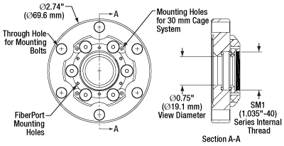
Mechanical Drawing of VC22 Series Flanges
- Ø2.75" CF Viewport with Ø1" Windows
- Viton O-Ring Metal to Glass Seal
- Sapphire, CaF2, or UVFS Window Included
- Clear Aperture: Ø0.71" (Ø18 mm)
- Not Compatible with Wedged Windows
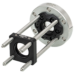
Thorlabs' Ø2.75" CF flange viewports allow for optical access into high-vacuum (HV) systems down to 10-8 Torr. These are fixed (non-rotating) flanges with Ø1" windows that provide a Ø0.71" (Ø18 mm) clear aperture (CA). Note that the CA is limited by the optic rather than the flange's internal diameter. These viewports have six 1/4" (M6) through holes for bolting onto any standard Ø2.75" CF flange. Please note that mounting hardware is not included. Our HV CF viewports can be purchased with one of three uncoated windows: sapphire, CaF2, or UVFS. Additionally, the provided window may be replaced with any of our Ø1" flat windows that are 4.9 - 5.15 mm thick.

- Ø2.75" CF Flange (Includes One O-Ring)
- Compatible with Ø1" Windows
- Not Compatible with Wedged Windows
Thorlabs' Ø2.75" CF flange does not include a window but is compatible with any Thorlabs Ø1" window that is 4.9 to 5.15 mm thick. When combined with the appropriate window, this flange allows for optical access into high-vacuum (HV) systems down to 10-8 Torr. This fixed (non-rotating) flange has six 1/4" (M6) through holes for bolting onto any standard Ø2.75" CF flange. Please note that mounting hardware is not included.
The CF-style flange utilizes a knife-edge mechanism to create an airtight seal between mating pieces. To create the seal, a copper gasket (available below) is most often employed. As the bolts of the mating pair are tightened, the knife edge "bites" into the copper gasket, deforming it. The extruded metal fills any machining marks or surface defects, yielding a leak-tight seal.

- VMH6 Stainless Steel (18-8) Mounting Hardware Set Includes:
- Six Bolts (Silver-Plated, 1/4"-28 x 1.50", 12-Point Heads)
- Six Nuts and Twelve Washers
- Single-Use Copper Gaskets for Forming a Seal Between Ø2.75" CF Flanges
- 101 Copper Alloy (99.99% Pure), OFHC (Oxygen-Free High Conductivity)
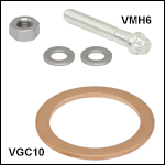
- VGC10: 1/4-Hard Copper Gaskets
- VGA10: Annealed Copper Gaskets
Thorlabs offers mounting hardware and single-use copper gaskets for mating Ø2.75" CF flanges. These flanges utilize a knife-edge mechanism to create an airtight seal between mating pieces. To create the seal, a copper gasket is most often employed. As the bolts of the mating pair are tightened, the knife edge bites into the copper gasket, deforming it. The extruded metal fills all the machining marks and surface defects, which yields a leak-tight seal.
1/4-hard and annealed copper gaskets are sold in sets of 10. We recommend the 1/4-hard copper gaskets for most applications; for more delicate devices, such as viewports, we recommend using the softer annealed copper gaskets to lower the chance of deformation in the optic due to stress in the flange. The set of stainless steel mounting hardware includes six silver-plated bolts, six nuts, and twelve washers. The silver plating on the bolts acts as a lubricant to prevent galling between the stainless steel surfaces of the bolt and the nut.
Instructions
First ensure the knife-edge mating surfaces of the CF flanges are free from debris or scratches. Then choose the desired bolt hole orientation and insert the gasket, aligning leak-test grooves on the flanges if present. Slide a washer onto the bolt, insert the bolt through the flanges, and add another washer before screwing on the nut. Hand tighten each bolt, then use two wrenches to hold the bolt head and turn the nut. Tighten the nuts gradually in 1/8 to 1/4 turn increments in an alternating crisscross star pattern until the desired tightness is reached. Following these steps will result in a reliable seal with even gasket compression and deformation.
 Products Home



 Zoom
Zoom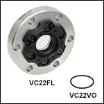
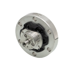
 High-Vacuum Viewports for Ø1" Flat Windows