16 mm Cage Cube-Mounted Turning Prism Mirrors
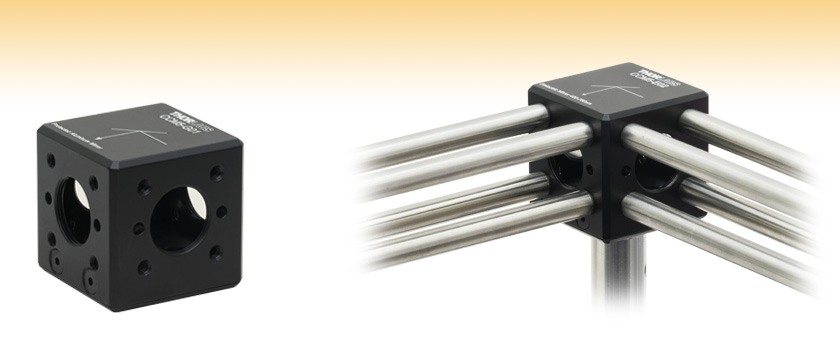
- Metallic- or Dielectric-Coated Turning Prism Mirrors
- Premounted in 16 mm Cage Cubes
- Compatible with SM05 Lens Tubes, Ø1/2" Optical Posts,
and 16 mm Cage Systems
CCM5-G01
4-40 Tapped Holes Provide
Compatibility with Thorlabs’
16 mm Cage System
8-32-Tapped Hole Allows for 1/2" Post Mounting

Please Wait
Click to Enlarge
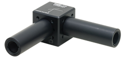
Figure 1.1 CCM5-M01 Cage Cube Shown with SM05 Lens Tubes
Features
- Choose from Seven Coating Options
- Metallic: UV-Enhanced Aluminum, Protected Aluminum, Protected Gold, Protected Silver
- Dielectric: E02 (400 - 750 nm), E03 (750 - 1100 nm), or K13 Nd:YAG (532 nm and 1064 nm)
- Compatible with Our Ø1/2" Lens Tubes and 16 mm Cage System
- Part Number and Coating are Engraved on the Housing for Easy Identification
- Post Mountable
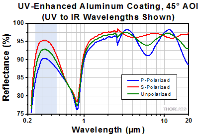
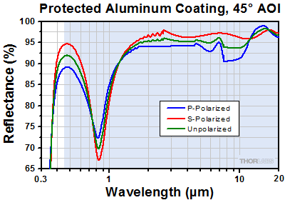
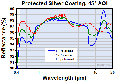
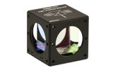
These Cage-Cube-Mounted Turning Mirrors provide additional flexibility when building optical devices based upon our 16 mm cage system and SM05 lens tube products. The mounted turning mirrors are prealigned so that the reflected beam exits to within ±20 arcmin of 90°, which can reduce the time needed for aligning the mirror in a setup. For higher accuracy or more alignment flexibility, see our 90° turning mirror kinematic mounts. The turning mirrors on this page are available with any of seven reflective coatings: UV-enhanced aluminum, protected aluminum, protected silver, protected gold, E02 broadband dielectric (400 - 750 nm), E03 broadband dielectric (750 - 1100 nm), or K13 Nd:YAG dielectric (532 nm and 1064 nm). A complete list of mirror specifications is provided on the Specs tab. Reflectance plots and data are provided on the Graphs tab.
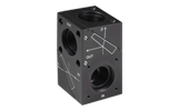
The bottom of the CCM5 cubes have either an 8-32 tapped hole for imperial parts or an M4 tapped hole for metric parts. The entrance and exit ports of these cubes also have SM05 threading (0.535"-40) as well as 4-40 taps on their sides which accept our SM05 Lens Tubes and Ø4 mm cage rods, respectively (refer to Figure 1.1 and the application image above). These mounted turning mirrors can be connected to other cage cubes through the use of our cage rods and SRSCA adapters.
| Item # | CCM5-F01(/M) | CCM5-G01(/M) | CCM5-P01(/M) | CCM5-M01(/M) | CCM5-E02(/M) | CCM5-E03(/M) | CCM5-K13(/M) |
|---|---|---|---|---|---|---|---|
| Unmounted Prism Item # | MRA20-F01 | MRA20-G01 | MRA20-P01 | MRA20-M01 | MRA20-E02 | MRA20-E03 | MRA20-K13 |
| Reflective Coating | UV-Enhanced Aluminum | Protected Aluminum | Protected Silver | Protected Gold | E02 Dielectric | E03 Dielectric | Nd:YAG Dielectric |
| Reflectance for 0° to 45° AOI |
Ravg > 90% (250 - 450 nm) |
Ravg > 90% (450 nm - 2.0 μm) |
Ravg > 97% (450 nm - 2 μm) Ravg > 95% (2 - 20 μm) |
Ravg > 96% (800 nm - 20.0 μm) |
Ravg > 99% (400 - 750 nm) |
Ravg > 99% (750 - 1100 nm) |
Rs and Rp: >98% (532 nm) >99% (1064 nm) |
Metallic-Coated Mirrors
| Item # | CCM5-F01(/M) | CCM5-G01(/M) | CCM5-P01(/M) | CCM5-M01(/M) |
|---|---|---|---|---|
| Unmounted Prism Item # | MRA20-F01 | MRA20-G01 | MRA20-P01 | MRA20-M01 |
| Reflective Coating | UV-Enhanced Aluminum | Protected Aluminum | Protected Silver | Protected Gold |
| Reflectance (Wavelength Range) |
Ravg > 90% (250 - 450 nm) | Ravg > 90% (450 nm - 2 μm) Ravg > 95% (2 - 20 μm) |
Ravg > 97% (450 nm - 2 μm) Ravg > 95% (2 - 20 μm) |
Ravg > 96% (800 nm - 20 μm) |
| Ports | 2 Ports, Each with SM05 (0.535"-40) Threading and Four 4-40 Taps for Cage Rods | |||
| Post Mounting | 8-32 (M4) Tapped Hole | |||
| Mirror Substrate | N-BK7a | |||
| Housing Material | Engraved Black Anodized Aluminum Housing | |||
| Surface Flatness (@ 633 nm) | <λ/10 Over Clear Aperture (Peak to Valley) | |||
| Clear Aperture | Ø12.5 mm | |||
| Surface Quality | 40-20 Scratch-Dig | |||
| Beam Path Deviation | 90° ± 20 arcmin | |||
Dielectric-Coated Mirrors
| Item # | CCM5-E02(/M) | CCM5-E03(/M) | CCM5-K13(/M) |
|---|---|---|---|
| Unmounted Prism Item # | MRA20-E02 | MRA20-E03 | MRA20-K13 |
| Reflective Coating | E02 Dielectric | E03 Dielectric | Nd:YAG Dielectric |
| Reflectance (Wavelength Range) |
Ravg > 99% (400 - 750 nm) | Ravg > 99% (750 - 1100 nm) | Rs and Rp: >98% (532 nm) >99% (1064 nm) |
| Ports | 2 Ports, Each with SM05 (0.535"-40) Threading and Four 4-40 Taps for Cage Rods | ||
| Post Mounting | 8-32 (M4) Tapped Hole | ||
| Mirror Substrate | N-BK7a | ||
| Housing Material | Engraved Black Anodized Aluminum Housing | ||
| Surface Flatness (@ 633 nm) | <λ/10 Over Clear Aperture (Peak to Valley) | ||
| Clear Aperture | Ø12.5 mm | ||
| Surface Quality | 10-5 Scratch-Dig | ||
| Beam Path Deviation | 90° ± 20 arcmin | ||
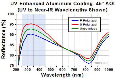
The shaded regions in the graphs denote the ranges over which we guarantee the specified reflectance. Please note that the reflectance outside of these bands is typical and can vary from lot to lot, especially in out-of-band regions where the reflectance is fluctuating or sloped.
UV-Enhanced Aluminum Coating (250 - 450 nm)
Protected Aluminum Coating (450 nm - 20 µm)
Protected Silver Coating (450 nm - 20 µm)
Protected Gold Coating (800 nm - 20 µm)
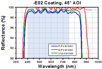
These plots show the reflectivity of our -E02 (400 - 750 nm) and -E03 (750 - 1100 nm) dielectric coatings for a typical coating run. The shaded region in each graph denotes the spectral range over which the coating is highly reflective. Due to variations in each run, this recommended spectral range is narrower than the actual range over which the optic will be highly reflective. If you have any concerns about the interpretation of this data, please contact Tech Support. For applications that require a mirror that bridges the spectral range between the dielectric coatings, please consider a metallic mirror.
-E02 Coating (400 - 750 nm)
Excel Spreadsheet with Raw Data for -E02 Coating, 8° and 45° AOI
-E03 Coating (750 - 1100 nm)
Excel Spreadsheet with Raw Data for -E03 Coating, 6° and 45° AOI
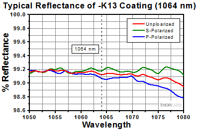
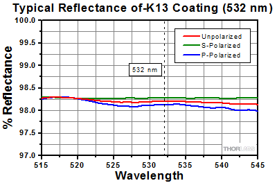
-K13 Coating (532 nm and 1064 nm)
These plots show the reflectance of our Nd:YAG (532 nm and 1064 nm) dielectric coating for a typical coating run. Although there will be variations in the broadband reflectance from run to run, this optic is guaranteed to meet the reflectivity specification at 532 nm and 1064 nm (see the table on the Overview tab). If you have any concerns about the interpretation of this data, please contact Tech Support.
Excel Spreadsheet with Raw Data for Dielectric Nd:YAG Laser Line Coating, 8° (Unpolarized) and 45° (S- and P-Polarized) AOI
Thorlabs offers a wide selection of optics optimized for use with Nd:YAG lasers. Please see below for more information.
| Posted Comments: | |
Franklin Wei
(posted 2021-06-22 17:26:50.05) Having an opposite-chirality version of these (with the 8-32 tap opposite from where it currently is) would add flexibility. YLohia
(posted 2021-06-28 10:52:39.0) Thank you for your feedback. We will consider this feature in a future revision of this product. Aritz Lazcoz
(posted 2019-12-09 10:26:42.523) The M4 tapped hole placed at the bottom of the CCM5 cubes has a critical drawback: instead of having a mechanical top, the hole directly reaches one of the surfaces of the Silver Turning Prism Mirror. We have screwed a long M4 screw till the end and it has produced an unintended rotation of the prealigned mirror, which has destroyed the factory precision of this piece. This is an expected use case that should be avoided by a proper design of the piece. llamb
(posted 2019-12-10 09:52:09.0) Thank you for your feedback, and I apologize for the inconvenience with this product. I have added this product idea into our internal engineering forum for improvement. I have also reached out to you directly to assess if a return or replacement is needed. In general, we do not recommend threading a screw into the CCM5- series turning mirrors further than 0.235". cmar5964
(posted 2016-07-15 17:40:39.563) From the step file it looks like the prism hypotenuse and thus reflecting surface is not actually the diagonal through the cube. Instead, I measure it to be offset by about 108 microns. This would mean that a beam entering centrally exits slightly off center. Is that actually the case or an artifact of the conversion from step to ipt that I have done? |
 Products Home









 16 mm Cage Cube-Mounted Turning Mirrors