Calcium Fluoride Bi-Convex Lenses, AR Coated: 2 - 5 µm
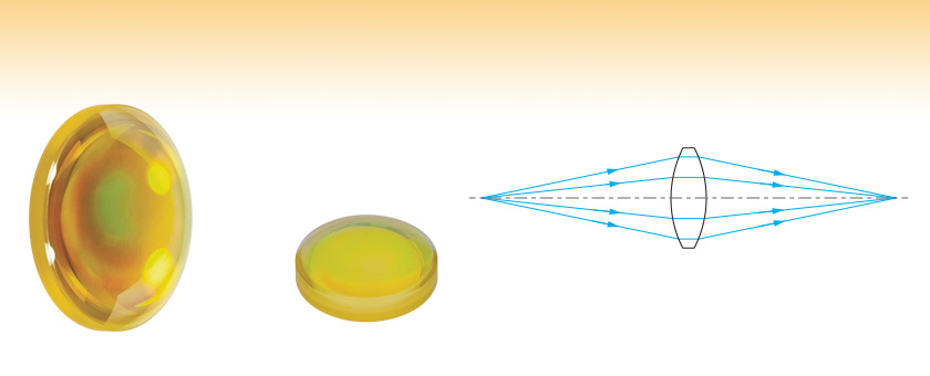
- AR Coating Optimized for the 2 - 5 µm Range
- Choose from Ø1/2" or Ø1"
LB5774-E1
LB5766-E1

Please Wait
| Common Specifications | |
|---|---|
| Substrate Material | Vacuum UV Grade Calcium Fluoridea |
| AR Coating Range | 2.0 - 5.0 μm |
| Reflectance over Coating Range (at 0° AOI) |
<1.25% (Avg.) <3.0% (Abs.) |
| Transmission over Coating Range (at 0° AOI) |
>94% (Avg.) >90% (Abs.) |
| Diameter Tolerance | +0.0/-0.1 mm |
| Thickness Tolerance | ±0.1 mm |
| Focal Length Tolerance | ±1% |
| Surface Quality | 40-20 (Scratch-Dig) |
| Spherical Surface Powerb | 3λ/2c |
| Spherical Surface Irregularity (Peak to Valley) |
λ/2c |
| Centration | <3 arcmin |
| Clear Aperture | >90% of Diameter |
| Design Wavelength | 588 nm |
Features
- Vacuum UV Grade Calcium Fluoride Substrate
- Ø1/2" and Ø1" Versions Available
- Broadband AR Coating for the 2.0 - 5.0 μm Range
- Focal Lengths from 15.0 mm to 200.0 mm
Thorlabs' Ø1/2" and Ø1" Calcium Fluoride (CaF2) Bi-Convex Lenses are available uncoated or with a broadband AR coating optimized for the 2 µm to 5 μm spectral range deposited on both surfaces. This coating greatly reduces the surface reflectivity of the substrate, yielding an average transmission in excess of 94% over the entire AR coating range. See the Graphs tab for detailed information.
CaF2 is commonly used for applications requiring high transmission in the infrared and ultraviolet spectral ranges. The material exhibits a low refractive index, varying from 1.35 to 1.51 within its usage range of 180 nm to 8.0 μm. Calcium fluoride is also fairly chemically inert and offers superior hardness compared to its barium fluoride, magnesium fluoride, and lithium fluoride cousins.
Bi-convex lenses are popular for many finite imaging applications. Both surfaces are spherical and have the same radius of curvature, minimizing aberrations in situations where the object and image distances are equal or nearly equal. As a guideline, bi-convex lenses are the best choice for minimizing aberrations if the conjugate ratio (object distance : image distance) is between 5:1 and 1:5. Outside this range, plano-convex lenses are usually preferred.
| Click on the red Document icon next to the item numbers below to access the Zemax file download. Our entire Zemax Catalog is also available. |
| Selection Guide |
|---|
| Calcium Fluoride Lenses |
| Other MIR Lenses |
| Other Spherical Singlets |
| Plano-Convex |
| Bi-Convex |
| Best Form |
| Plano-Concave |
| Bi-Concave |
| Positive Meniscus |
| Negative Meniscus |
2 - 5 µm AR Coating Graphs
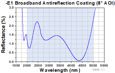
Click to Enlarge
Click Here for an Excel File with Plot Data
Shown above is a graph of the measured percent reflectance of the enhanced AR coating as a function of wavelength. The average reflectance in the 2 - 5 μm range is <1.25%. The blue shading indicates the region for which the AR coating is optmized. Performance outside of the specified range is not guaranteed and varies from lot to lot. The excel file above provides the coating curve data over an extended wavelength range.
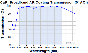
Click to Enlarge
Click Here for an Excel File with Plot Data
Shown above is a graph of the measured percent transmission of the enhanced AR coating as a function of wavelength. The blue shading indicates the region for which the AR coating is optmized. Performance outside of the specified range is not guaranteed and varies from lot to lot. The excel file above provides the coating curve data over an extended wavelength range.
CaF2 Transmission
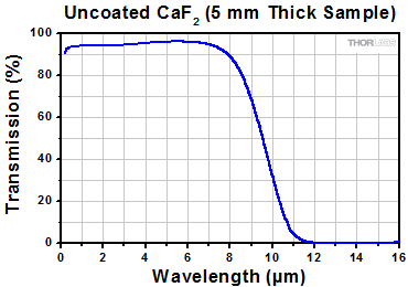
Click to Enlarge
Click Here for an Excel File with Plot Data
Shown above is a graph of the measured transmission of an uncoated, 5 mm thick sample of CaF2.
Wavelength-Dependent Focal Length Shift
The paraxial focal length of a lens is wavelength dependent. The focal length listed below for a given lens corresponds to the value at the design wavelength (i.e., the focal length at 588 nm). Since CaF2 offers high transmission from 0.18 - 8.0 µm, users may wish to use these lenses at other popular wavelengths. Click on the icons below to view theoretically-calculated focal length shifts for wavelengths within the 0.18 - 8.0 µm range.
The blue shading indicates the region for which the AR coating is optimized. Please see the Graphs tab for more information.
| Recommended Mounting Options for Thorlabs Lenses | ||
|---|---|---|
| Item # | Mounts for Ø2 mm to Ø10 mm Optics | |
| Imperial | Metric | |
| (Various) | Fixed Lens Mounts and Mini-Series Fixed Lens Mounts for Small Optics, Ø5 mm to Ø10 mm | |
| (Various) | Small Optic Adapters for Use with Standard Fixed Lens Mounts, Ø2 mm to Ø10 mm | |
| Item # | Mounts for Ø1/2" (Ø12.7 mm) Optics | |
| Imperial | Metric | |
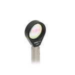
| LMR05 | LMR05/M | Fixed Lens Mount for Ø1/2" Optics |
| MLH05 | MLH05/M | Mini-Series Fixed Lens Mount for Ø1/2" Optics |
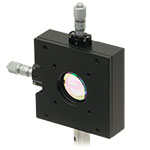
| LM05XY | LM05XY/M | Translating Lens Mount for Ø1/2" Optics |
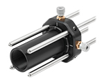
| SCP05 | 16 mm Cage System, XY Translation Mount for Ø1/2" Optics | |
| (Various) | Ø1/2" Lens Tubes, Optional SM05RRC Retaining Ring for High-Curvature Lenses (See Below) |
|
| Item # | Mounts for Ø1" (Ø25.4 mm) Optics | |
| Imperial | Metric | |
| LMR1 | LMR1/M | Fixed Lens Mount for Ø1" Optics |
| LM1XY | LM1XY/M | Translating Lens Mount for Ø1" Optics |
| ST1XY-S | ST1XY-S/M | Translating Lens Mount with Micrometer Drives (Other Drives Available) |
| CXY1A | 30 mm Cage System, XY Translation Mount for Ø1" Optics | |
| (Various) | Ø1" Lens Tubes, Optional SM1RRC Retaining Ring for High-Curvature Lenses (See Below) |
|
| Item # | Mount for Ø1.5" Optics | |
| Imperial | Metric | |
| LMR1.5 | LMR1.5/M | Fixed Lens Mount for Ø1.5" Optics |
| (Various) | Ø1.5" Lens Tubes, Optional SM1.5RR Retaining Ring for Ø1.5" Lens Tubes and Mounts |
|
| Item # | Mounts for Ø2" (Ø50.8 mm) Optics | |
| Imperial | Metric | |
| LMR2 | LMR2/M | Fixed Lens Mount for Ø2" Optics |
| LM2XY | LM2XY/M | Translating Lens Mount for Ø2" Optics |
| CXY2 | 60 mm Cage System, XY Translation Mount for Ø2" Optics |
|
| (Various) | Ø2" Lens Tubes, Optional SM2RRC Retaining Ring for High-Curvature Lenses (See Below) |
|
| Item # | Adjustable Optic Mounts | |
| Imperial | Metric | |
| LH1 | LH1/M | Adjustable Mount for Ø0.28" (Ø7.1 mm) to Ø1.80" (Ø45.7 mm) Optics |
| LH2 | LH2/M | Adjustable Mount for Ø0.77" (Ø19.6 mm) to Ø2.28" (Ø57.9 mm) Optics |
| VG100 | VG100/M | Adjustable Clamp for Ø0.5" (Ø13 mm) to Ø3.5" (Ø89 mm) Optics |
| SCL03 | SCL03/M | Self-Centering Mount for Ø0.15" (Ø3.8 mm) to Ø1.77" (Ø45.0 mm) Optics |
| SCL04 | SCL04/M | Self-Centering Mount for Ø0.15" (Ø3.8 mm) to Ø3.00" (Ø76.2 mm) Optics |
| LH160C | LH160C/M | Adjustable Mount for 60 mm Cage Systems, Ø0.50" (Ø13 mm) to Ø2.00" (Ø50.8 mm) Optics |
| SCL60CA | SCL60C/M | Self-Centering Mount for 60 mm Cage Systems, Ø0.15" (Ø3.8 mm) to Ø1.77" (Ø45.0 mm) Optics |
Mounting High-Curvature Optics
Thorlabs' retaining rings are used to secure unmounted optics within lens tubes or optic mounts. These rings are secured in position using a compatible spanner wrench. For flat or low-curvature optics, standard retaining rings manufactured from anodized aluminum are available from Ø5 mm to Ø4". For high-curvature optics, extra-thick retaining rings are available in Ø1/2", Ø1", and Ø2" sizes.
Extra-thick retaining rings offer several features that aid in mounting high-curvature optics such as aspheric lenses, short-focal-length plano-convex lenses, and condenser lenses. As shown in the animation to the right, the guide flange of the spanner wrench will collide with the surface of high-curvature lenses when using a standard retaining ring, potentially scratching the optic. This contact also creates a gap between the spanner wrench and retaining ring, preventing the ring from tightening correctly. Extra-thick retaining rings provide the necessary clearance for the spanner wrench to secure the lens without coming into contact with the optic surface.
| Posted Comments: | |
| No Comments Posted |


 Products Home



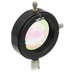
 CaF2, -E1 Coated