Beamsplitter Guide

Please Wait
Beamsplitter Overview
Beamsplitters separate incident light into two or more beams of the same wavelength. These exiting beams are differentiated by either their optical power (non-polarizing) or polarization states (polarizing). Non-polarizing beamsplitters are specified by their splitting ratio, i.e. the amount of light in the reflected arm versus the amount of light in the transmitted arm, while polarizing beamsplitters are specified by their extinction ratio, i.e. the ratio of P-polarized light to S-polarized light in the transmitted arm.
Most beamsplitters are produced in two varieties: plate beamsplitters and beamsplitting cubes. Other beamsplitting solutions are available, including pellicle beamsplitters, crystal beamsplitters, Brewster Windows and wedged plates. Each variety is described below with some of their features and strengths. For detailed spec comparisons, see the BS Selection Guide tab.
The beams exiting a beamsplitter have the same wavelength as the incident light. This distinguishes beamsplitters from dichroic mirrors and hot and cold mirrors, which split an input beam into two wavelength bands. Conversely, some polarizing optics have two or more exiting beams whose polarization states are not distinct from each other; these are known as polarizers.

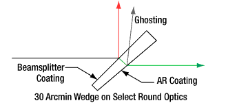
Plate Beamsplitters
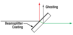
Plate beamsplitters offer a relatively lightweight solution in a small footprint, which is beneficial in space-constrained setups. They are usually placed in a beam path at a 45° angle of incidence (AOI). The plates are coated with a thin film that reflects a portion of the beam while the rest is transmitted. The transmitted beam is offset from the incident beam due to refraction. At the back surface of a plate beamsplitter, a second reflection is created, often referred to as a ghost reflection or ghosting. To mitigate ghosting, Thorlabs may apply an anti-reflective (AR) coating, 30 arcmin wedge, or a combination of the two to the back surface of some of our plate beamsplitters.
In high-sensitivity applications, the reflected beam may need to be put through a compensation plate to match its path length to that of the transmitted beam. A compensation plate is a window of the same material and thickness as the beamsplitter, which accounts for the path difference acquired traveling through the beamsplitter.
Plate Beamsplitter Features
| Beamsplitters | Polarization | Available Wedged | Backside AR Coating | AOI | Bandwidth | Mounted | Applications and Features | Diagram (Click to Enlarge) |
|---|---|---|---|---|---|---|---|---|
| Economy Beamsplitters | Non-Polarizing | No | No | 45° | Broadband | Unmounted | Preliminary Set-Ups; Single-Use Applications |
 |
| Standard Non-Polarizing Plate Beamsplitters |
Yesa | Most | 45° | Broadband | Unmounted | Low Aberrations Compared to Cubes |
 |
|
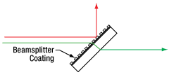
| Polka Dot Beamsplitter | No | No | 0 - 45° | Broadband | Unmounted | Splitting without Polarization Artifacts; Controlling Lamp Intensity |
 |
|
| Ultrafast Beamsplitters with Low Dispersion |
Non-Polarizingb | No | Yes | 45° | Broadband | Unmounted | Ultrafast Laser Experiments | 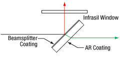 |
| Standard Polarizing Plate Beamsplitters |
Polarizing | Yesa | No | 45° | Narrowband | Unmounted | Small Footprint and Low Weight Compared to Cubes |
 |
Cube Beamsplitters
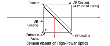
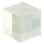
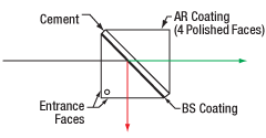
Cube beamsplitters are a more mechanically robust solution when compared to plates or pellicles. They are constructed from two right-angle prisms, joined at their hypotenuses, with a thin film coating at the interface which causes the beam to split. The two halves are connected either by cement or optical contacting. Optical contacting is a more difficult means of binding two glass surfaces together, but it removes the need for cement, which is often the limiting factor in calculating laser damage threshold.
These cubes are ordinarily placed in a beam path at a 0° angle of incidence (AOI) and cause one exiting beam to stay in line with the optical axis and one exiting beam to be deviated 90°. One of the benefits of a 0° AOI is that the transmitted beam is minimally offset by refraction. This and the AR coatings on the entrance and exit faces reduce ghosting. Conversely, their thickness introduces increases in optical path length and group delay dispersion (GDD) when compared to plate or pellicle beamsplitters. Cube beamsplitters also require more space to mount, which can be a disadvantage in space-constrained setups. See the BS Cube Mounting tab for our cube mounting options.
Cube Beamsplitter Features
| Beamsplitters | Polarization | Cemented | AR Coating | AOI | Bandwidth | Mounted | Applications and Features | Diagram (Click to Enlarge) |
|---|---|---|---|---|---|---|---|---|
| Standard Non-Polarizing Beamsplitter Cubes | Non-Polarizing | Yes | Yes | 0° | Broadband | Mounted and Unmounted |
Low Influence from Mechanical Stress Compared to Plate Beamsplitters |
 |
| Wire Grid Beamsplitters (Mounted and Unmounted) | Polarizing | Yes | Yes | 0° - 25° | Broadband | Mounted and Unmounted |
High Imaging Contrast; Wide Acceptance Angle | 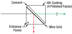 |
| Standard Polarizing Beamsplitter Cubes | Yes | Yes | 0° | Broadband | Mounted and Unmounted |
Transmits P-Polarized Light with Extinction Ratio TP:TS > 1000:1 | 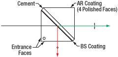 |
|
| Laser Line Beamsplitter Cubes (Mounted and Unmounted) |
Yes | Yes | 0° | Narrowband | Mounted and Unmounted |
Beam Sampling | ||
| High-Power, Laser Line Beamsplitter Cubes | No | Yes | 0° | Narrowband | Mounted and Unmounted |
High-Power Durability | 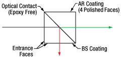 |
|
| Variable Beamsplitter | Yes | Yes | 0° | Narrowband or Broadband | Mounted | Beam Polarization Analysis | 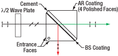 |
|
| Circular Polarizing Beamsplitter Cubes | Yes | Yes | 0° | Narrowband or Broadband | Mounted | Generate Circularly, Elliptically, or Linearly Polarized Light |  |
Pellicle Beamsplitters
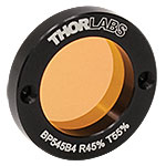
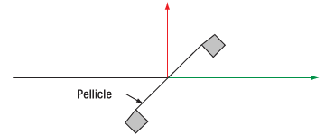
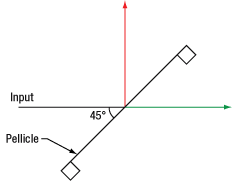
Pellicle beamsplitters are comprised of a nitrocellulose membrane mounted under tension in a metal housing. Since the membrane is only a few microns thick, the second surface reflection is superimposed on the first, effectively eliminating ghosting. Pellicle beamsplitters minimize chromatic dispersion and aberrations, making them ideal for use in applications requiring focused beams.
While pellicles are among the lightest beamsplitting solutions, their membrane is extremely delicate and flammable. These optics should be handled carefully and only used in low-power applications. A pellicle beamsplitter should be chosen carefully to match an experiment's operating conditions, as thin film interference causes sinusoidal fluctuations in the output intensity with wavelength. For details on interference effects, see the main presentation of our Pellicle Beamsplitters.
Pellicle Beamsplitter Features
| Beamsplitters | Polarization | Cemented | AR Coating |
AOI | Bandwidth | Mounted | Applications and Features | Diagram (Click to Enlarge) |
|---|---|---|---|---|---|---|---|---|
| Pellicle Beamsplitters | Non-Polarizing | No | No | 45° | Broadband | Mounted and Unmounted |
Minimizes Chromatic Dispersion; Eliminates Ghosting; Low Power Applications |
 |
Crystal Beamsplitters
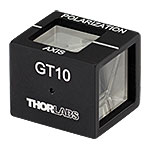
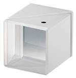
Some crystals, like calcite, MgF2, quartz, α-BBO, and YVO4, can induce polarization in transmitted and reflected beams via the light's interaction with the optical axes of the crystals. The main advantage of crystal beamsplitters over polarizing plate or cube beamsplitters is their relatively high laser damage threshold and extinction ratio, making them ideal for polarizing laser sources. These beamsplitters can be either single bulk crystals or multiple crystals bonded to each other through either cement or optical contacting. Care should be taken when changing the temperature of these crystals, as some may experience thermal shock if the temperature change is too rapid, leading to fractures or breakage.
The different substrates of our crystal beamsplitters each offer an exceptional extinction ratio of 100 000:1 within their respective wavelength ranges. Our α-BBO beamsplitters are ideal for UV, calcite is best for visible to near-IR, and yttrium orthovanadate (YVO4) has the best performance from near-IR to mid-IR.
Crystal Beamsplitter Features
| Beamsplitters | Polarization | Cemented | AR Coating | AOI | Bandwidth | Mounted | Applications and Features | Diagram (Click to Enlarge) |
|---|---|---|---|---|---|---|---|---|
| Calcite Beam Displacers | Polarizing | No | No | 0° | Broadband | Unmounted | Parallel Exit Beams; Orthogonally Polarized Outputs; High Extinction Ratio in Both Beams |
 |
| Yttrium Orthovanadate Beam Displacers | Yes | Mounted and Unmounted |
||||||
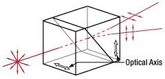
| Wollaston Prisms | Mosta | Yes | 0° | Broadband | Mounted and Unmounted |
Non-Orthogonal Beam Exit Angles, Symmetric Around Entrance Beam; Orthogonally Polarized Outputs; High Extinction Ratio in Both Beams |
 |
|
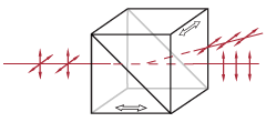
| Rochon Prisms | No | No | 0° | Broadband | Mounted | Non-Orthogonal Beam Exit Angles; Orthogonally Polarized Outputs; High Extinction Ratio in Both Beams; Ordinary Ray is Not Deflected |
 |
|
| Glan-Taylor Polarizers | No | Yes | 0° | Broadband | Mounted | Low Scatter; Air-Spaced Birefringent Crystal Prisms |
 |
|
| Glan-Laser Polarizers (α-BBO and Calcite) |
No | Yes | 0° | Broadband | Mounted | Specialized Glan-Taylor Polarizer Designed for High-Power Applications |
||
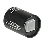
| Double Glan-Taylor Polarizers | No | No | 0° | Broadband | Mounted | Ideal for High-Quality Polarization with Extinction Ratios Greater than 100 000:1 in the 0.35 - 2.3 µm Wavelength Range |
 |
|
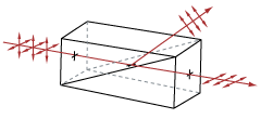
| Glan-Thompson Polarizers (Mounted and Unmounted) |
Yes | Yes | 0° | Broadband | Mounted and Unmounted |
Offers the Wide Field of View of Calcite Polarizers While Maintaining a High Extinction Ratio |
 |
Brewster Windows
Brewster windows are windows of uncoated substrate (UV Fused Silica) that form a circular profile with the optical axis when positioned at Brewster's Angle. At this angle, the p-polarized component of incident light enters and exits the window without reflection losses, while the s-polarized component is partially reflected. Brewster windows can be used in series as polarizers or to improve a beam's polarization ratio.
Brewster Window Features
| Beamsplitters | Polarization | Cemented | AR Coating | AOI | Bandwidth | Mounted | Applications and Features | Diagram (Click to Enlarge) |
|---|---|---|---|---|---|---|---|---|
| Brewster Windows | Polarizing | No | No | 55° 32' @ 633 nm |
Broadband | Unmounted | Improving Polarization Ratio | 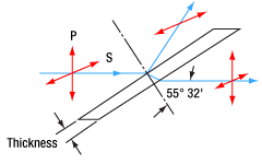 |
Wedged Plate Beamsplitter
A wedged plate beamsplitter splits a single input beam into multiple copies through successive reflections and refractions. This creates separate, progressively more attenuated copies of the incident beam at different exits angles. The angular deviation of each exit beam can easily be calculated. For details, see here.
Wedged Plate Beamsplitter Features
| Beamsplitters | Polarization | Cemented | AR Coating | AOI | Bandwidth | Mounted | Applications and Features | Diagram (Click to Enlarge) |
|---|---|---|---|---|---|---|---|---|
| Wedged Plate Beamsplitter | Non-Polarizing | No | No | Variable | Broadband | Unmounted | Duplicating a Source Beam | 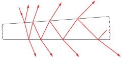 |
Beamsplitter Selection Guide
Thorlabs' portfolio contains many different kinds of beamsplitters, which can split beams by intensity or by polarization. We offer plate and cube beamsplitters, though other form factors exist, including pellicle and birefringent crystal. For an overview of the different types and a comparison of their features and applications, please see our overview. Many of our beamsplitters come in premounted or unmounted variants. In this tab is a complete listing of our beamsplitter offerings. To explore the available types, wavelength ranges, splitting/extinction ratios, transmission, and available sizes for each beamsplitter category, click More [+] in the appropriate row.Plate Beamsplitters
| Non-Polarizing Plate Beamsplitters |
|---|
| Polarizing Plate Beamsplitters |
|---|
Cube Beamsplitters
| Non-Polarizing Cube Beamsplitters |
|---|
| Polarizing Cube and Polyhedron Beamsplitters |
|---|
Pellicle Beamsplitters
| Non-Polarizing Pellicle Beamsplitters |
|---|
Crystal Beamsplitters
| Polarizing Crystal Beamsplitters |
|---|
Other
| Other Beamsplitters |
|---|
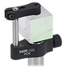
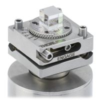
Thorlabs offers a variety of mounting solutions for our beamsplitter cubes. The mounts listed here allow our cubes to be post-mounted or integrated into our 16 mm or 30 mm cage systems. Post-mountable solutions are compatible with our Ø1/2" Posts as well as Ø1" Posts with 8-32 (M4) taps.
| Post-Mountable Mounts for Beamsplitter Cubes | ||||||||
|---|---|---|---|---|---|---|---|---|
| Click Photo to Enlarge (Cubes Not Included) |
 |
 |
 |
 |
 |
 |
 |
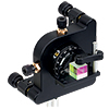 |
| Item # | PCM(/M) | BSH10(/M) BSH05(/M) BSH20(/M) BSH1(/M) BSH2(/M) |
FBTB(/M) | KM100PM(/M) | KM200PM(/M) | KM100B(/M) | KM200B(/M) | K6XS |
| Required Accessories | Base: PCMP(/M) | - | - | Clamp: PM3(/M) or PM4(/M) |
Clamp: PM3(/M) or PM4(/M) |
Clamp: PM3(/M) or PM4(/M) |
Clamp: PM3(/M) or PM4(/M) |
Adapter: K6A1(/M) |
| Mounting Options | Ø1/2" Posts | Ø1/2" Postsa,b | Ø1/2" Posts | Ø1/2" Posts | Ø1/2" Posts | Ø1/2" Posts | Ø1/2" Posts | Ø1/2" Posts |
| Features | Compact | Compact | Glue-In Mount with Precision Tip, Tilt, and Rotation | Tip and Rotation | Tip and Rotation | Kinematic Mount | Kinematic Mount | 6-Axis Mount |
| Compatible Beamsplitter Cube Size(s) |
Up to 20 mm | 10 mm, 1/2", 20 mm, 1", 2" |
5 mm | Up to 20 mmc Up to 1" d |
Up to 20 mmc Up to 1" d Up to 2" e |
Up to 20 mmc Up to 1" d |
Up to 20 mmc Up to 1" d Up to 2" e |
5 mm 10 mm 1/2" |
| Cage System Mounts for Beamsplitter Cubes | |||||||||
|---|---|---|---|---|---|---|---|---|---|
| Click Photo to Enlarge (Cubes Not Included) |
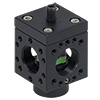 |
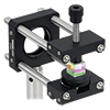 |
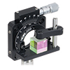 |
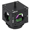 |
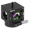 |
 |
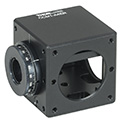 |
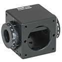 |
 |
| Item # | Cage Cube: SC6W |
ARV1 | CRM1(/M) or CRM1P(/M) | Cage Cube: C4W or C6W a | CCM1-4ER(/M) | CCM1-A4ER(/M) | CCM1-B4ER(/M) | CCM1-C4ER(/M) | |
| Required Accessories | Clamp: SB6C, Platform: SPM2 |
- | Adapter: K6A1(/M) |
Clamp: B6C, Platform: B3C(/M) or B4C(/M) |
Clamp: B6C, Platform: B3CR(/M) or B4CRP(/M) |
- | - | - | - |
| Mounting Options |
16 mm Cage Systems | 30 mm Cage Systems | 30 mm Cage Systems or Ø1/2" Posts | 30 mm Cage Systems | 30 mm Cage Systems or Ø1/2" Posts | ||||
| Features | Compact | Compact | Rotation Mount | Fixed or Kinematic Platforms | Rotation Platforms | - | One Rotation Mount | Two Rotation Mounts @ 180° | Two Rotation Mounts @ 90° |
| Compatible Beamsplitter Cube Size(s) |
10 mm | 5 mm 10 mm |
5 mm 10 mm 1/2" |
1/2" 20 mm 1" |
5 mm (with BS5CAM Adapter) 10 mm (with BS10CAM Adapter) 1/2" (with BS127CAM Adapter) 20 mm (with BS20CAM Adapter) 1" (Directly Compatible) |
||||
Thorlabs Lab Fact: Beamsplitter Package Matters
We present laboratory measurements of the polarization angle, split ratio, and total throughput power of a beam transmitted through Thorlabs plate, cube, and pellicle beamsplitters. While all non-polarizing beamsplitters function similarly, the exact performance is different for different types of beamsplitter. Each type of beamsplitter contains its own advantages and disadvantages compared to other types of beamsplitters. Appropriate choice of beamsplitter is essential to sensitive experimental systems. We present a complete analysis and comparison of optical parameters for three common types of non-polarizing beamsplitters.
For our experiment we used the previous-genration HRS015 stabilized HeNe as the light source for our investigation. A linear polarizer is used to set the laser beam's polarization axis to 45° in order to provide equal s- and p-polarized light incident on the beamsplitter. The beamsplitter under investigation was then placed in the beampath, and its split beams directed to appropriate detectors. The total power though the optic, polarization states, split ratios, and angle of incidence effects were investigated under this configuration.
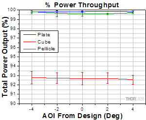
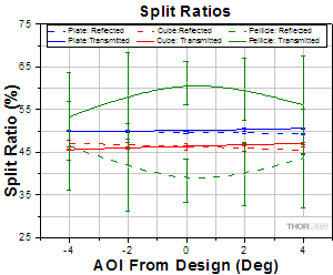
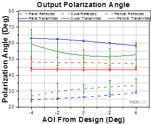
The plots below summarize the measured results for all three types of beamsplitters. From these graphs the performance of each optic can be easily compared to one another. Figure 4.1 summarizes the results for the total power throughput for each optic. The total power throughput is measured as the fraction of input power. While the plate and pellicle beamsplitters perform rather similarly, the cube shows signs of absorption inside the optic. Additionally, this plot shows the relative insensitivity of throughput power to angle of incidence. Figure 4.2 summarizes the results for the output polarization angle for each optic. The cube shows the most similar polarization angles between the reflected and transmitted beams, with the plate producing the largest difference in polarization between beams. Figure 4.3 summarizes the results for the split ratio, as a fraction of input power, for the beamsplitters. Here it can be shown that the plate beamsplitter demonstrates the most ideal for 50/50 power splitting. For details on the experimental setup employed and the results summarized here, please click here.
Click to Enlarge
Figure 4.1 Beamsplitter Power Throughput Comparison
Click to Enlarge
Figure 4.3 Beamsplitter Split Ratio Comparison
Click to Enlarge
Figure 4.2 Beamsplitter Polarization Angle Comparison
| Posted Comments: | |
user
(posted 2023-11-08 11:09:05.277) Regarding the change in polarization angle between reflected and transmitted beams, do all of your cube and plate beamsplitters behave similarly to the BSW10 tested in the lab facts slides?
i.e. with an IR beamsplitter such as BSW42, do you see the same behaviour where the cube BS preserves polarisation angle and the plate BS does not?
Thanks cdolbashian
(posted 2023-11-17 11:24:39.0) Thank you for reaching out to us with this inquiry. It is very likely you would see the same effect. Reflections from non-normal incidence of dielectric stacks tend to produce this effect. Following the trends we show here, you should be able to pick a style of polarizer which is best for your application. bruce harrison
(posted 2019-04-04 21:27:10.27) How about how beamsplitters are used as beam combiners? How does the side 2 coating come into play with the different types of splitters? How well can they combine two beams of the same wavelength and then two beams of different wavelength? YLohia
(posted 2019-04-05 04:59:46.0) Hello, thank you for your valuable feedback. We have added this to our list of tasks and intend to have this information available on our website as a future Lab Fact or just a general guide on the relevant beamsplitter pages. |
 Products Home



 Beamsplitters