
 Operation Starter Sets page for pricing and availability information")
Complete Laser Diode (LD) Operation Starter Sets

- Bundles Include LD Controller, TEC Controller, LD Mount, Collimation Optic, and Accessories
- Ideal for Stable and Safe Operation of Standard Laser Diodes
Included Accessories
LTC56B
Ø5.6 mm LD Controller Kit
(Controller Cables Included)
SM1NT
C230TMD-B
(Coating Varies
with Item #)
BA2
S1TM09
SPW301
SPW909
WS02
2x
TR1.5
2x
PH1.5
OVERVIEW
| Key Specifications | |
|---|---|
| Specification | Value |
| LDC205C Laser Diode Current Controllera | |
| LD Current Control Range | 0 to ±500 mA |
| Compliance Voltage | >10 V |
| Photocurrent Control Range | 25 µA to 10 mA |
| Small Signal 3 dB Bandwidth | DC to 150 kHz |
| TED200C Temperature Controllera | |
| TEC Current Control Range | -2 A to +2 A |
| Compliance Voltage | >6 V |
| Maximum Output Power | 12 W |
| Thermistor Control Range | 10 Ω to 20 kΩ / 100 Ω to 200 kΩ (2 Ranges) |
| Supported IC Sensors | AD590, AD592, LM135, LM335 |
| LDM56(/M) Laser Diode Mount with Integrated TECb | |
| Supported Laser Diode Package/ Pin Configurations |
Ø5.6 mm TO Can, A, B, C, D, E, G, and H |
| Laser Current (Max) | 2 A |
| TEC Current | 5 A |
| TEC Heating/Cooling Capacity | 8 W (@ 25 ºC) |
| RF Modulation Frequency | 100 kHz to 600 MHz |
Included Items:
- LDC205C Benchtop LD Current Controller
- TED200C Benchtop Temperature Controller
- LDM56(/M) LD/TEC Mount for Ø5.6 mm TO-Can Laser Diodes
- AR-Coated Collimation Optic:
- LTC56A(/M): C230TMD-A for 350 - 700 nm
- LTC56B(/M): C230TMD-B for 600 - 1050 nm
- LTC56C(/M): C230TMD-C for 1050 - 1700 nm
- Connection Cables and Related Accessories (See Kit Contents Tab for Details)
 Click To Enlarge
For setups needing additional working distance, our 30 mm cage system components can be mounted into the face plate.
Thorlabs' LTC56 Series Kits are complete laser diode (LD) current and temperature controller sets including a laser diode mount, collimating optic, and accessories. They include the LDC205C LD Current Controller, TED200C Temperature Controller, LDM56(/M) Laser Diode Mount, and other items necessary for the stable and safe operation of standard Ø5.6 mm laser diodes. These starter sets are offered at a discount over the cost of individual components.
The kit is offered in three versions depending of the anti-reflection coating of the collimation optic: LTC56A(/M) for 350 - 700 nm, LTC56B(/M) for 600 - 1050 nm, and LTC56C(/M) for 1050 - 1700 nm. For detailed information about the included components, please refer to the Kit Contents tab above. Each unit ships with two cables, one for the temperature controller (CAB420-15) and one for the laser diode controller (CAB400). Although all necessary cables are packaged with the purchase of the controllers and starter sets presented above, replacements can be purchased separately.
The LDMXY Flexure Adapter, sold separately below, attaches to the laser diode mount and enables precise positioning of a collimating aspheric lens. The two piece design also enables coarse repositioning of the attached 30 mm or 60 mm cage system that is independent of the laser diode and collimating optic. We also offer the LDM56DJ Mounting Flange for use with 532 nm DPSS lasers, available separately below.
These sets are available with imperial or metric mounting hardware. The LDC205C and TED200C controllers operate with a line voltage of 100, 115, or 230 VAC.
| Laser Diode Accessory Selection Guide | |||||
|---|---|---|---|---|---|
| Other Temperature Controlled Mounts |
Passive Mounts | Passive Mounts with Collimation Package |
Strain Relief Cables | Diode Sockets | Other Controllers |
 |
 |
 |
 |
 |
 |
CONTROLLER SPECS
| Item # | LDC205C |
|---|---|
| Current Control (Constant Current Mode) | |
| Control Range | 0 to ±500 mA |
| Compliance Voltage | >10 V |
| Resolution | 10 µA |
| Accuracy | ±0.5 mA |
| Noise Without Ripple (10 Hz to 10 MHz, rms, typ.) |
< 3 µA |
| Ripple (50/60 Hz, rms, typ.) | < 2 µA |
| Transients (Typ.) | < 0.5 mA |
| Drift, 24 hours (typ., 0-10Hz, at constant ambient temperature) |
<10 µA |
| Temperature Coefficient | <50 ppm/ °C |
| Current Limit | |
| Setting Range | 0 to >500 mA |
| Resolution | 10 µA |
| Accuracy | ±1.5 mA |
| Power Control (Constant Power Mode) | |
| Photocurrent Control Range | 25 µA to 10 mA |
| Photocurrent Resolution | 1 µA |
| Photocurrent Accuracy | ±10 µA |
| Analog Modulation Input | |
| Input Resistance | 10 kΩ |
| Small Signal 3 dB Bandwidth, CC Mode |
DC to 150 kHz |
| Modulation Coefficient, CC Mode |
50 mA/V ±5% |
| Modulation Coefficient, CP Mode |
1 mA/V ±5% |
| Laser Current Monitor Output | |
| Load Resistance | >10 kΩ |
| Transmission Coefficient | 20 V/A ±5% |
| General Data | |
| Safety Features | Interlock, Laser Current Limit, Soft Start, Short Circuit when Laser Off, Open Circuit Detection, Over Temperature Protection |
| Display | LED, 5 Digits |
| Connector for Laser, Photodiode, Interlock & Laser On Signal |
9-pin D-Sub Jack |
| Connectors for Control Input / Output |
BNC |
| Chassis Ground Connector | 4 mm Banana Jack |
| Line Voltage / Frequency | 100 V, 115 V, 230 V +15% –10% each / 50 to 60 Hz |
| Maximum Power Consumption | 30 VA |
| Mains Supply Overvoltage | Category II (Cat II) |
| Operating Temperature | 0 to +40 °C |
| Storage Temperature | -40 to +70 °C |
| Relative Humidity | Max. 80% Up to 30 °C, Decreasing to 50% at 40 °C |
| Pollution Degree (Indoor Use Only) | 2 |
| Operation Altitude | <2000 m |
| Warm-up Time for Rated Accuracy | 10 min |
| Weight | <3.1 kg |
| Dimensions (W X H X D) without Operating Elements |
146 mm x 66 mm x 290 mm |
| Dimensions (W X H X D) with Operating Elements |
146 mm x 77 mm x 320 mm |
| Item # | TED200C |
|---|---|
| TEC Current Output | |
| Control Range | -2 A to +2 A |
| Compliance Voltage | >6 V |
| Maximum Output Power | 12 W |
| Measurement Resolution | 1 mA |
| Measurement Accuracy | ±10 mA |
| Noise and Ripple (typ.) | <1 mA |
| TEC Current Limit | |
| Setting Range | 0 to >2 A |
| Resolution | 1 mA |
| Setting Accuracy | ±20 mA |
| Thermistor Sensorsa | |
| Control Range | 10 Ω to 20 kΩ / 100 Ω to 200 kΩ (2 Ranges) |
| Resolution (20kΩ / 200 kΩ Range) |
1 Ω / 10 Ω |
| Accuracy (20 kΩ / 200 kΩ Range) |
±10 Ω / ±100 Ω |
| Temperature Stability, 24 hoursb (20 kΩ / 200 kΩ Range) |
<0.5 Ω / <5 Ω |
| IC Sensors | |
| Supported Sensors | AD590, AD592, LM135, LM335 |
| Control Range with AD590, LM135 |
-45 °C to +145 °C |
| Control Range with AD592 | -25 °C to +105 °C |
| Control Range with LM335 | -40 °C to +100 °C |
| Resolution | 0.01 °C |
| Accuracy | ±0.1 °C |
| Temperature Stability, 24 Hours | <0.002 °C |
| Temperature Control Input | |
| Input Resistance | 10 kΩ |
| Control Voltage | -10V to +10V |
| Transmission Coefficient Thermistor (20 kΩ / 200 kΩ Range) |
2 kΩ/V / 20 kΩ/V ±5% |
| Transmission Coefficient IC-Sensors |
20 °C/V ±5% |
| Temperature Control Output | |
| Load Resistance | >10 kΩ |
| Transmission Coefficient Thermistor (20 kΩ / 200 kΩ Range) |
500 mV/kΩ / 50 mV/kΩ ±5% |
| Transmission Coefficient IC-Sensors |
50 mV/ °C ±5% |
| General Data | |
| Safety Features | TEC Current Limit, Short Circuit when TEC Off, Missing Sensor Protection, Open Circuit Detection, Over Temperature Protection |
| Display | LED, 5 Digits |
| Connector for Sensor, TE Cooler, TEC On Signal |
15-pin D-sub Jack |
| Connectors for Control Input / Output |
BNC |
| Chassis Ground Connector | 4mm Banana Jack |
| Line Voltage / Frequency | 100 V, 115 V, 230 V +15% -10% each / 50 to 60Hz |
| Maximum Power Consumption |
60 VA |
| Mains Supply Overvoltage | Category II (Cat II) |
| Operating Temperature | 0 to +40 °C |
| Storage Temperature | -40 to +70 °C |
| Relative Humidity | Max. 80% Up to 30 °C, Decreasing to 50% at 40 °C |
| Pollution Degree (Indoor Use Only) | 2 |
| Operation Altitude | <2000 m |
| Warm-up Time for Rated Accuracy |
10 min |
| Weight | <3.1 kg |
| Dimensions (W x H x D) without Operating Elements |
146 mm x 66 mm x 290 mm |
| Dimensions (W x H x D) with Operating Elements |
146 mm x 77 mm x 320 mm |
DIODE MOUNT SPECS
| Item # | LDM56(/M) | |
|---|---|---|
| Laser Diode | ||
| Supported Laser Diode Package | Ø5.6 mm | |
| Supported Pin Configuration(s) | A, B, C, D, E, Ga, and H (Switch Selectable) |
|
| Accepted Pin Lead Diameter | 0.015" - 0.020" (0.38 mm - 0.51 mm) | |
| Accepted Pin Lead Length | Up to 0.6" (15.24 mm) | |
| Laser Current (Max) | 2 A | |
| RF Modulation Frequency (Bias-T) | 100 kHz to 600 MHz | |
| RF Input Impedance | 50 Ω | |
| RF Max Power | 200 mW | |
| Temperature Controller | ||
| TEC Current (Max)b | 5 Ac | |
| TEC Voltage (Max) | 4 V | |
| TEC Heating/Cooling Capacity | 8 W (25 ºC) | |
| Typical Temperature Range (LD Dependent) |
0 to 70 °C | |
| Temperature Sensor |
Thermistor | 10 kΩ ± 3% @ 25 °C, NTC, β = 3977 K ± 0.75% |
| Thermocouple | AD592AN (1 μA/°K) | |
| General Specifications | ||
| Laser Interface | DB9 Female | |
| TEC Interface | DB9 Male | |
| RF Modulation Connector | SMA | |
| Interlock Connector | 2.5 mm Phono Jack | |
| Indicator | Green LED - LD Enabled | |
| Mounting Holes |
Imperial Mounts | 1/4"-20 (9 Places) |
| Metric Mounts | M6 x 1.0 (9 Places) | |
| Cage Compatibility | 4-40 Taps (8 Places) for 30 mm and 60 mm Cage Systems |
|
| Operating Temperature | 10 to 40 °C | |
| Storage Temperature | 10 to 80 °C | |
| Dimensions (L x W x D) | 4.00" x 4.00" x 2.07" (101.6 mm × 101.6 mm × 52.6 mm) |
|
| Weight | 1.9 lbs (0.87 kg) | |

Click to Enlarge
LDM56(/M) Mounting Features Diagram
FRONT & BACK PANEL
LDC205C Front Panel
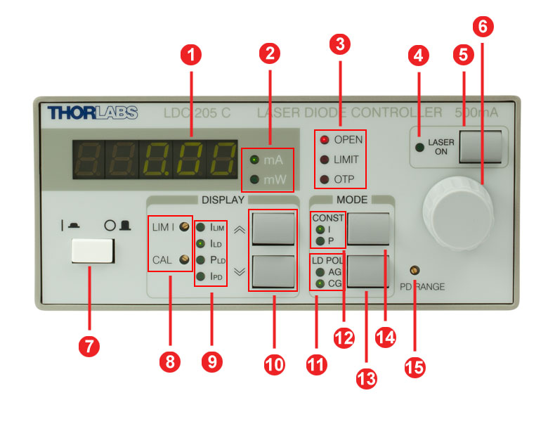
| Callout | Connection | Callout | Connection |
|---|---|---|---|
| 1 | 5-Digit LED Display | 9 | Display Indicators |
| 2 | Display Units | 10 | Up/Down Display Select |
| 3 | Interlock Indicators | 11 | Diode Polarization Indicator |
| 4 | Laser Status Indicator | ||
| 5 | Laser Current On/Off Switch | 12 | Output Mode Indicator |
| 6 | Display Adjustment Knob | 13 | Diode Polarization Select |
| 7 | Supply Power Switch | 14 | Output Mode Select |
| 8 | Current Limit and Power Calibration Pots | 15 | Photodiode Current Range Pot |
LDC205C Back Panel

| Callout | Connection | Callout | Connection |
|---|---|---|---|
| 1 | TTL Input "LD REM" 0 to 5 V | 6 | Connector "LD OUT" for LD, PD, Interlock, & Status LED |
| 2 | Modulation Input / Analog Control Input "MOD IN", -10 to +10 V | 7 | Serial Number of the Unit |
| 3 | Analog Control Output "CTL OUT", -10 to +10 V |
8 | Indicator / Switch for Line Voltage (Included in Fuse Holder) |
| 4 | Cooling Fan | ||
| 5 | 4 mm Banana Jack for Chassis Ground | 9 | Power Connector and Fuse Holder |
TED200C Front Panel
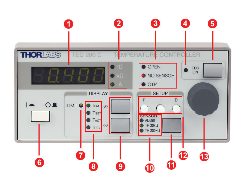
| Callout | Connection | Callout | Connection |
|---|---|---|---|
| 1 | 5-Digit LED Display | 8 | Display Indicators |
| 2 | Display Units | 9 | Up/Down Display Select |
| 3 | Interlock Indicators | 10 | Selected Sensor Inticators |
| 4 | TEC Status Indicator | 11 | Sensor Select Key |
| 5 | TEC Current On/Off Switch | 12 | Potentiometers for PID Gain Settings |
| 6 | Supply Power Switch | ||
| 7 | Potentiometer for Current Limit Setting | 13 | Display Adjustment Knob |
TED200C Back Panel

| Callout | Connection | Callout | Connection |
|---|---|---|---|
| 1 | Analog Temperature Control Input "Tune In", -10 to 10 V | 5 | 15-pin D-sub Jack for the TEC Element and the Temperature Sensor "TE OUTPUT" |
| 2 | Analog Temperature Control Output "CTL Out", -10 to 10 V | 6 | Serial Number of the Unit |
| 3 | Cooling Fan | 7 | Indicator / Switch for Line Voltage (Included in Fuse Holder) |
| 4 | 4 mm Banana Jack for Chassis Ground | 8 | Power Connector and Fuse Holder |
PIN DIAGRAMS
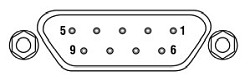
LDC205C - Benchtop LD Current Controller
| Pin | Connection | Pin | Connection |
|---|---|---|---|
| 1 | Interlock and Status LASER ON/OFF | 6 | Not Connected |
| 2 | Photodiode Cathode | 7 | Laser Diode Cathode (with Polarity Anode Grounded - AG) |
| 3 | Laser Diode Ground | 8 | Laser Diode Anode (with Polarity Cathode Grounded - CG) |
| 4 | Photodiode Anode | ||
| 5 | Ground for Pin 1 | 9 | Not Connected |
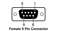
Laser Diode Connector
Laser Diode Remote
TTL Input (0 to +5 V)
Modulation Input
Analog Control Input
(-10 V to 10V)
Control Output
Analog Control Output
(0 to ±10 V)
Chassis Ground

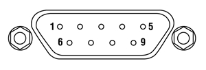
TED200C - Benchtop Temperature Controller
| Pin | Connection | Pin | Connection |
|---|---|---|---|
| 1 | Status LED (+) TEC ON/OFF | 9 | Not Connected |
| 2 | Not Connected | 10 | Transducer AD 590/592 (-), LM 135/335 (+) |
| 3 | Thermistor (-), Ground | 11 | Transducer AD 590/592 (+), LM 135/335 (+) |
| 4 | Thermistor (+) | ||
| 5 | TEC (+) | 12 | Not Connected |
| 6 | TEC (+) | 13 | TEC (-), Status-LED (-) |
| 7 | TEC (+) | 14 | TEC (-), Status-LED (-) |
| 8 | AGND LM 135/335 (-) | 15 | TEC (-), Status-LED (-) |
Temperature Sensor and Controller

Analog Temperature Control Input
Analog Temperature Control Output
LDM56(/M) - Laser Diode Mount
LD Controller: D-Type Female
| Pin | Signal | Description |
|---|---|---|
| 1 | Interlock and Status Pin (LDC Specific) |
Laser Diode (LD) Status Indicator and Interlock Circuits input. |
| 2 | Photodiode Cathode | This pin is connected to the 9 o'clock pin on the laser socket when the photodiode (PD) polarity switch is set to anode ground (AG). It is attached to ground and the 12 o'clock and 6 o'clock pins on the laser socket when the PD polarity switch is set to cathode ground (CG). |
| 3 | Laser Ground (Case) | This pin is connected to the 12 o'clock and 6 o'clock pins on the laser socket and corresponds to the settings of the LD and PD polarity switches (i.e. If the LD and PD switches are set to AG then this pin grounds the anodes of the laser and photodiodes). |
| 4 | Photodiode Anode | This pin is connected to the 9 o'clock pin on the laser socket when the PD polarity switch is set to CG. It is attached to ground and the 12 o'clock and 6 o'clock pins on the laser socket when the PD polarity switch is set to AG. |
| 5 | Interlock and Status Return |
Status and interlock circuitry return. |
| 6 | Laser Diode Voltage (Cathode) |
This pin is connected to LD interface pin 7, through a 499 Ω resistor, when the LD polarity switch is set to AG. It is attached directly to LD interface pin 3 when the LD polarity switch is set to CG. |
| 7 | Laser Diode Cathode | This pin is connected to the 3 o'clock pin on the laser socket when the LD polarity switch is set to AG, and it floats otherwise. |
| 8 | Laser Diode Anode | This pin is connected to the 3 o'clock pin on the laser socket when the LD polarity switch is set to CG, and it floats otherwise. |
| 9 | Laser Diode Voltage (Anode) |
This pin is connected to LD interface pin 8, through a 499 Ω resistor, when the LD polarity switch is set to CG. It is attached directly to LD interface pin 3 when the LD polarity switch is set to AG. |
TEC Controller: D-Type Male
| Pin | Signal | Description |
|---|---|---|
| 1 | TEC Lockout (+) | This pin is connected to the anode of the photo-relay side of the TEC Lockout circuit. When using Thorlabs TEDs no external circuitry is required. To use these features with third-party controllers please refer to the Status and Interlock section of the mount's manual. |
| 2 | +Thermistor | The 10 kΩ at 25 °C NTC thermistor (provided for temperature feedback). |
| 3 | -Thermistor | The thermistor return pin. |
| 4 | +TEC | This pin is connected to the positive terminal of the TEC element. |
| 5 | -TEC and TEC Lockout (-) | This pin is connected to the negative terminal of the TEC element, and also is common to the cathode of the photo-relay of the TEC Lockout circuit - refer to the Status and Interlock section of the mount's manual. |
| 6 | N.C. | Not Used. |
| 7 | AD592(-) | The negative terminal of the AD592 temperature transducer. When using Thorlabs TEDs no external circuitry is required. To use this device with third party controllers it must be properly biased. Refer to Analog Devices AD592 Data for application information. |
| 8 | N.C. | Not Used. |
| 9 | AD592(+) | The positive terminal of the AD592 |
Optional Remote Interlock
2.5 mm Female Mono Phono Jack
| Specification | Value |
|---|---|
| Type of Mating Connector | 2.5 mm Mono Phono Jack |
| Open Circuit Voltage | +5 VDC with Respect to System Ground (When Used in Conjunction with Thorlabs Drivers) |
| Short Circuit Current | 10 mA DC (Typ.) |
| Connector Polarity | Tip: Positive; Barrel: Ground |
| Interlock Switch Requirements | Must be N.O. dry contacts. Under no circumstances should any external voltages be applied to the Interlock input. |
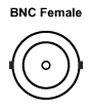
RF Laser Modulation Input
SMA Female
RF input for modulation with an external source up to 600 MHz. This is a 50 Ω input that is AC-coupled directly to the laser through a Bias-T network.
KIT CONTENTS
| Photo (Click to Enlarge) |
Quantity | Item # in Imperial Kits |
Item # in Metric Kits |
Description |
|---|---|---|---|---|
 |
1 | LDC205C | Benchtop LD Current Controller, ±500 mA HV | |
 |
1 | TED200C | Benchtop Temperature Controller, ±2 A / 12 W | |
 |
1 | LDM56 | LDM56/M | TE-Cooled Mount for Ø5.6 mm Laser Diodes, 1/4"-20 (M6) Taps |
 |
1 | LTC56A(/M) Kit: C230TMD-A | Mounted Aspheric Lens, AR: 350 - 700 nm, f = 4.51 mm, NA = 0.55 | |
| LTC56B(/M) Kit: C230TMD-B | Mounted Aspheric Lens, AR: 650 - 1050 nm, f = 4.51 mm, NA = 0.55 | |||
| LTC56C(/M) Kit: C230TMD-C | Mounted Aspheric Lens, AR: 1050 - 1700 nm, f = 4.51 mm, NA = 0.55 | |||
 |
1 | S1TM09 | SM1 to M9 x 0.5 Lens Cell Adapter | |
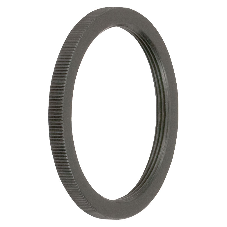 |
1 | SM1NT | SM1 (1.035"-40) Locking Ring | |
 |
2 | TR1.5 | TR40/M | Ø1/2" Optical Post, SS, 8-32 Setscrew, 1/4"-20 Tap, L = 1.5" (Ø12.7 mm Optical Post, SS, M4 Setscrew, M6 Tap, L = 40 mm) |
 |
2 | PH1.5 | PH40/M | Ø1/2" Post Holder, Spring-Loaded Hex-Locking Thumbscrew, L = 1.5" (Ø12.7 mm Post Holder, Spring-Loaded Hex-Locking Thumbscrew, L = 40 mm) |
 |
1 | BA2 | BA2/M | Mounting Base, 2" x 3" x 3/8" (50 mm x 75 mm x 10 mm) |
 |
1 | SPW909 | Spanner Wrench for SM1-Threaded Adapters, Length = 1" | |
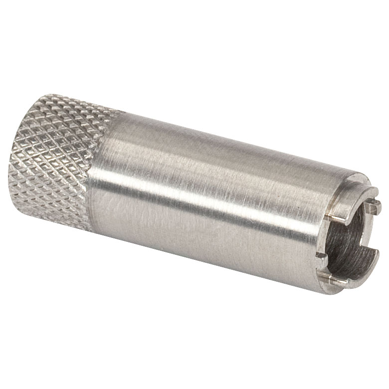 |
1 | SPW301 | Spanner Wrench for an M9 x 0.5 Optics Housing, Length = 1" | |
 |
1 | WS02 | Fabric Grounding Wrist Strap, Adjustable Circumference, 6 ft Coiled Cord | |
 |
2 Pieces | SS25E63Da | SS6M16Da | 1/4"-20 Stainless Steel Setscrew with Hex on Both Ends, 5/8" Long (M6 x 1.0 Stainless Steel Setscrew with Hex on Both Ends, 16 mm Long) |
PID TUTORIAL
PID Basics
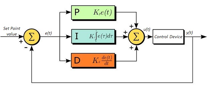
The PID circuit is often utilized as a control loop feedback controller and is commonly used for many forms of servo circuits. The letters making up the acronym PID correspond to Proportional (P), Integral (I), and Derivative (D), which represents the three control settings of a PID circuit. The purpose of any servo circuit is to hold the system at a predetermined value (set point) for long periods of time. The PID circuit actively controls the system so as to hold it at the set point by generating an error signal that is essentially the difference between the set point and the current value. The three controls relate to the time-dependent error signal. At its simplest, this can be thought of as follows: Proportional is dependent upon the present error, Integral is dependent upon the accumulation of past error, and Derivative is the prediction of future error. The results of each of the controls are then fed into a weighted sum, which then adjusts the output of the circuit, u(t). This output is fed into a control device, its value is fed back into the circuit, and the process is allowed to actively stabilize the circuit’s output to reach and hold at the set point value. The block diagram below illustrates the action of a PID circuit. One or more of the controls can be utilized in any servo circuit depending on system demand and requirement (i.e., P, I, PI, PD, or PID).
Through proper setting of the controls in a PID circuit, relatively quick response with minimal overshoot (passing the set point value) and ringing (oscillation about the set point value) can be achieved. Let’s take as an example a temperature servo, such as that for temperature stabilization of a laser diode. The PID circuit will ultimately servo the current to a Thermo Electric Cooler (TEC) (often times through control of the gate voltage on an FET). Under this example, the current is referred to as the Manipulated Variable (MV). A thermistor is used to monitor the temperature of the laser diode, and the voltage over the thermistor is used as the Process Variable (PV). The Set Point (SP) voltage is set to correspond to the desired temperature. The error signal, e(t), is then the difference between the SP and PV. A PID controller will generate the error signal and then change the MV to reach the desired result. For example, if e(t) states that the laser diode is too hot, the circuit will allow more current to flow through the TEC (proportional control). Since proportional control is proportional to e(t), it may not cool the laser diode quickly enough. In that event, the circuit will further increase the amount of current through the TEC (integral control) by looking at the previous errors and adjusting the output to reach the desired value. As the SP is reached (e(t) approaches zero), the circuit will decrease the current through the TEC in anticipation of reaching the SP (derivative control).
Please note that a PID circuit will not guarantee optimal control. Improper setting of the PID controls can cause the circuit to oscillate significantly and lead to instability in control. It is up to the user to properly adjust the PID gains to ensure proper performance.
PID Theory
The output of the PID control circuit, u(t), is given as
where
Kp= Proportional Gain
Ki = Integral Gain
Kd = Derivative Gain
e(t) = SP - PV(t)
From here we can define the control units through their mathematical definition and discuss each in a little more detail. Proportional control is proportional to the error signal; as such, it is a direct response to the error signal generated by the circuit:
Larger proportional gain results in larger changes in response to the error, and thus affects the speed at which the controller can respond to changes in the system. While a high proportional gain can cause a circuit to respond swiftly, too high a value can cause oscillations about the SP value. Too low a value and the circuit cannot efficiently respond to changes in the system.
Integral control goes a step further than proportional gain, as it is proportional to not just the magnitude of the error signal but also the duration of the error.
Integral control is highly effective at increasing the response time of a circuit along with eliminating the steady-state error associated with purely proportional control. In essence integral control sums over the previous error, which was not corrected, and then multiplies that error by Ki to produce the integral response. Thus, for even small sustained error, a large aggregated integral response can be realized. However, due to the fast response of integral control, high gain values can cause significant overshoot of the SP value and lead to oscillation and instability. Too low, and the circuit will be significantly slower in responding to changes in the system.
Derivative control attempts to reduce the overshoot and ringing potential from proportional and integral control. It determines how quickly the circuit is changing over time (by looking at the derivative of the error signal) and multiplies it by Kd to produce the derivative response.
Unlike proportional and integral control, derivative control will slow the response of the circuit. In doing so, it is able to partially compensate for the overshoot as well as damp out any oscillations caused by integral and proportional control. High gain values cause the circuit to respond very slowly and can leave one susceptible to noise and high frequency oscillation (as the circuit becomes too slow to respond quickly). Too low and the circuit is prone to overshooting the SP value. However, in some cases overshooting the SP value by any significant amount must be avoided and thus a higher derivative gain (along with lower proportional gain) can be used. The chart below explains the effects of increasing the gain of any one of the parameters independently.
| Parameter Increased | Rise Time | Overshoot | Settling Time | Steady-State Error | Stability |
|---|---|---|---|---|---|
| Kp | Decrease | Increase | Small Change | Decrease | Degrade |
| Ki | Decrease | Increase | Increase | Decrease Significantly | Degrade |
| Kd | Minor Decrease | Minor Decrease | Minor Decrease | No Effect | Improve (for small Kd) |
Tuning
In general the gains of P, I, and D will need to be adjusted by the user in order to best servo the system. While there is not a static set of rules for what the values should be for any specific system, following the general procedures should help in tuning a circuit to match one’s system and environment. A PID circuit will typically overshoot the SP value slightly and then quickly damp out to reach the SP value.
Manual tuning of the gain settings is the simplest method for setting the PID controls. However, this procedure is done actively (the PID controller turned on and properly attached to the system) and requires some amount of experience to fully integrate. To tune your PID controller manually, first the integral and derivative gains are set to zero. Increase the proportional gain until you observe oscillation in the output. Your proportional gain should then be set to roughly half this value. After the proportional gain is set, increase the integral gain until any offset is corrected for on a time scale appropriate for your system. If you increase this gain too much, you will observe significant overshoot of the SP value and instability in the circuit. Once the integral gain is set, the derivative gain can then be increased. Derivative gain will reduce overshoot and damp the system quickly to the SP value. If you increase the derivative gain too much, you will see large overshoot (due to the circuit being too slow to respond). By playing with the gain settings, you can maximize the performance of your PID circuit, resulting in a circuit that quickly responds to changes in the system and effectively damps out oscillation about the SP value.
| Control Type | Kp | Ki | Kd |
|---|---|---|---|
| P | 0.50 Ku | - | - |
| PI | 0.45 Ku | 1.2 Kp/Pu | - |
| PID | 0.60 Ku | 2 Kp/Pu | KpPu/8 |
While manual tuning can be very effective at setting a PID circuit for your specific system, it does require some amount of experience and understanding of PID circuits and response. The Ziegler-Nichols method for PID tuning offers a bit more structured guide to setting PID values. Again, you’ll want to set the integral and derivative gain to zero. Increase the proportional gain until the circuit starts to oscillate. We will call this gain level Ku. The oscillation will have a period of Pu. Gains for various control circuits are then given below in the chart.
Complete Laser Diode Operation Starter Sets
Part Number | Description | Price | Availability |
|---|---|---|---|
LTC56A/M | Laser Diode Starter Set with Current and Temperature Controllers, Mount, Accessories, Optic for 350-700 nm, Metric | $3,132.86 | Today |
LTC56B/M | Laser Diode Starter Set with Current and Temperature Controllers, Mount, Accessories, Optic for 600-1050 nm, Metric | $3,132.86 | Today |
LTC56C/M | Laser Diode Starter Set with Current and Temperature Controllers, Mount, Accessories, Optic for 1050-1700 nm, Metric | $3,132.86 | Today |
LTC56A | Laser Diode Starter Set with Current and Temperature Controllers, Mount, Accessories, Optic for 350-700 nm, Imperial | $3,132.86 | Today |
LTC56B | Laser Diode Starter Set with Current and Temperature Controllers, Mount, Accessories, Optic for 600-1050 nm, Imperial | $3,132.86 | Today |
LTC56C | Laser Diode Starter Set with Current and Temperature Controllers, Mount, Accessories, Optic for 1050-1700 nm, Imperial | $3,132.86 | Today |
XY Flexure Adapter

| LDMXY Adapter Specifications | |
|---|---|
| Flexure | |
| Optic Cell Travel | ±1.0 mm |
| Optic Cell Threading | SM1 (1.035"-40) Through Tapped |
| XY Adjusters | M3 x 0.25 (250 μm/rev) |
| Slip Plate | |
| Slip Plate Travel | ±1.0 mm (Coarse Adjustment) |
| Cage Compatibility | 4-40 Taps (8 Places) for 30 mm and 60 mm Cage Systems |
| General | |
| Material | Aluminum |
| Dimensions | 4.00" x 4.00" x 0.60" (101.6 mm x 101.6 mm x 15.2 mm) |
| Mass | 0.33 kg (0.73 lbs) |
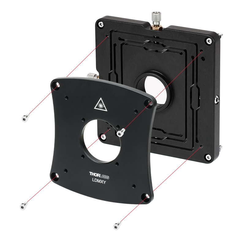
- XY Flexure Translation of SM1 Thread (±1.0 mm Travel)
- Slip Plate with Cage System Taps for Independent Translation (±1.0 mm Travel)
- Compatible with 30 mm and 60 mm Cage Systems
- Mounts Directly to the Front of LDM Series Laser Diode Mounts
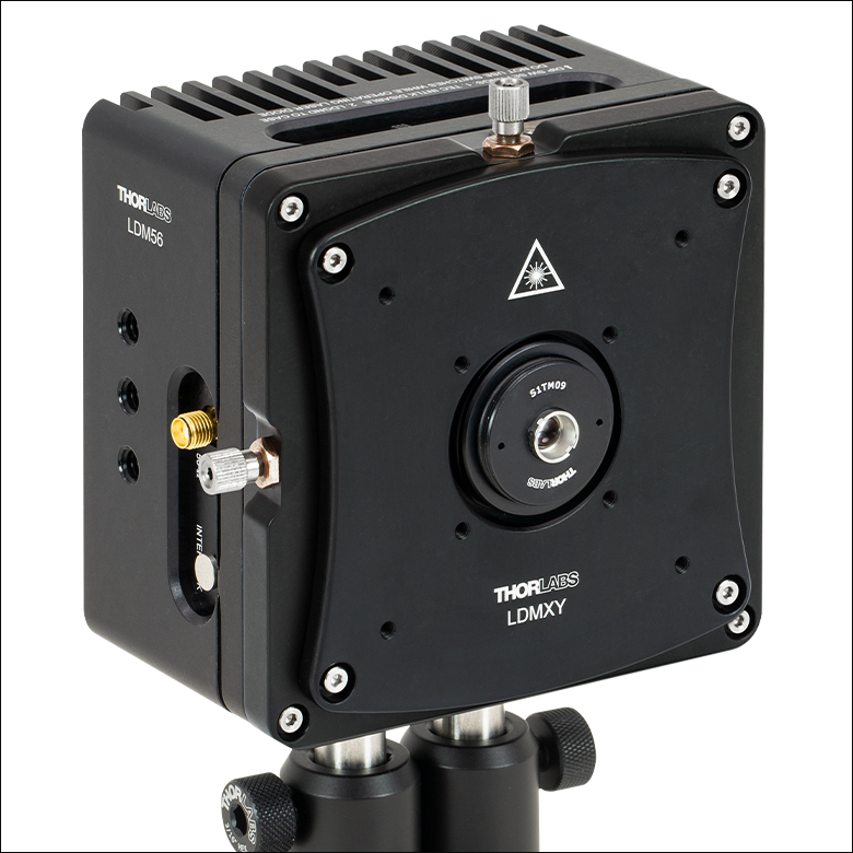
The LDMXY Flexure Adapter provides collimation optics with ±1.0 mm of XY translation. The translating optic cell is SM1 threaded for compatibility with our aspheric lens adapters and aspheric lenses. The front slip plate also offers ±1.0 mm of coarse XY translation independently of the SM1-threaded optic cell and features the same eight 4-40 taps for 30 mm and 60 mm cage system compatibility. This isolates the load of attached cage systems to the LDM Series LD Mount rather than the flexure mechanism. Four standard cap screws can be loosened to adjust the slip plate, while four captive screws are used to attach the LDMXY adapter to the laser diode mount. All screws are compatible with 5/64" (2.0 mm) hex balldrivers and hex keys.
Click to Enlarge
The LDMXY can be used to increase the working distance to the lens, as well as provide X and Y translation.
Click to Enlarge
The flexure translates the
SM1-threaded optic cell independently from the cage system slip plate.
Part Number | Description | Price | Availability |
|---|---|---|---|
LDMXY | XY Flexure Adapter for LDM Series Laser Diode Mounts | $412.58 | Today |
Mounting Flange for DPSS Lasers

The LDM56DJ mounting flange is used to secure a 532 nm DPSS laser to the LDM56(/M) temperature-controlled laser diode mount. To use, mount either the DJ532-10 or the DJ532-40 laser in the LDM56(/M) mount. Using the two 2-56 x 3/8" cap head screws provided with the flange, or with the mount itself, attach the flange to the mount.
Please note: this flange is sold separately from the LDM56(/M) Temperature Controlled Laser Diode Mount.
Part Number | Description | Price | Availability |
|---|---|---|---|
LDM56DJ | DPSS Laser Mounting Flange for LDM56(/M) Laser Diode Mount | $29.99 | Today |