

Fiber-Coupled LEDs

- UV, Visible, and NIR Versions
- Optimized Heat Management Results in Stable Output
- Integrated Chip Stores LED Operating Parameters
- Accepts SMA Fiber Connector
M625F2
625 nm Fiber-Coupled LED
Ø400 µm Core Patch Cable
(Not Included)
Integrated Power Cable
Large Heat Sink for
Optimized Heat Dissipation
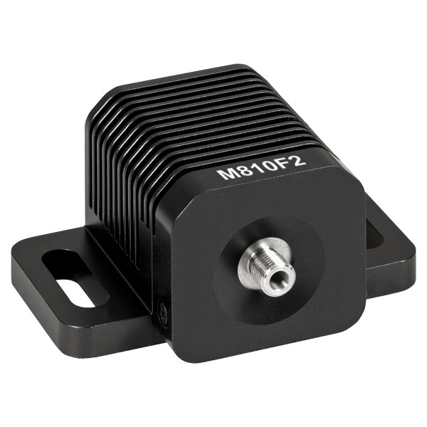
M385FP1
385 nm Fiber-Coupled LED
OVERVIEW
| Legend | |
|---|---|
| LED Mounted to a 50 mm Long Heat Sink | LED Mounted to a 34 mm Long Heat Sink |
| Item # | Color (Click for Spectrum)a |
Nominal Wavelengtha,b |
Ø200 µm Core Fiber Output (Typ.)c,d,e |
Ø400 µm Core Fiber Output (Typ.)c,e,f |
|---|---|---|---|---|
| M280F5g | Deep UV | 280 nm | 0.2 mW | 0.8 mW |
| M310F1g | Deep UV | 308 nm | 0.14 mW | 0.51 mW |
| M325F4g | Deep UV | 325 nm | 100 µW | 350 µW |
| M340F4g | Deep UV | 340 nm | 0.16 mW | 0.75 mW |
| M365FP1g | UV | 365 nm | 5.29 mW | 15.5 mW |
| M375F3g | UV | 375 nm | 1.57 mW | 4.23 mW |
| M385FP1g | UV | 385 nm | 7.7 mW | 23.2 mW |
| M395F3g | UV | 395 nm | 1.91 mW | 6.8 mW |
| M395FP1g | UV | 395 nm | 7.7 mW | 29.8 mW |
| M405F3g | UV | 405 nm | 0.93 mW | 3.7 mW |
| M405FP1g | UV | 405 nm | 7.7 mW | 24.3 mW |
| M415F3g | Violet | 415 nm | 7.0 mW | 21.3 mW |
| M430F1g | Violet | 430 nm | 2.9 mW | 7.5 mW |
| M455F3 | Royal Blue | 455 nm | 5.4 mW | 24.5 mW |
| M470F4 | Blue | 470 nm | 6.5 mW | 20 mW |
| M490F4 | Blue | 490 nm | 0.9 mW | 2.8 mW |
| M505F3 | Cyan | 505 nm | 3.7 mW | 11.7 mW |
| M530F3 | Green | 530 nm | 3.2 mW | 9.6 mW |
| MINTF4 | Mint | 554 nm | 8.5 mW | 28 mW |
| M565F3h | Lime | 565 nm | 4.4 mW | 13.5 mW |
| M590F3 | Amber | 590 nm | 1.5 mW | 4.6 mW |
| M595F2h | PC Amber | 595 nm | 4.0 mW | 11.5 mW |
| M617F2 | Orange | 617 nm | 4.4 mW | 13.2 mW |
| M625F2 | Red | 625 nm | 5.7 mW | 17.5 mW |
| M660FP1 | Red | 660 nm | 4.7 mW | 15.5 mW |
| M680F4 | Deep Red | 680 nm | 2.8 mW | 9 mW |
| M700F4 | Deep Red | 700 nm | 1.9 mW | 6.4 mW |
| M740F2 | Far Red | 740 nm | 2.1 mW | 6.0 mW |
| M780F2 | IR | 780 nm | 1.15 mW | 7.0 mW |
| M810F3 | IR | 810 nm | 6.1 mW | 19.3 mW |
| M850F3 | IR | 850 nm | 4.1 mW | 13.4 mW |
| M880F2 | IR | 880 nm | 0.58 mW | 3.4 mW |
| M940F3 | IR | 940 nm | 4.2 mW | 14.2 mW |
| M970F3 | IR | 970 nm | 2.4 mW | 8.1 mW |
| M1050F3 | IR | 1050 nm | 0.92 mW | 3.0 mW |
| M1100F1 | IR | 1100 nm | 1.1 mW | 5.4 mW |
| M1200F1 | IR | 1200 nm | 0.9 mW | 2.5 mW |
| M1300F1 | IR | 1300 nm | 0.77 mW | 2.31 mW |
| M1450F1 | IR | 1450 nm | 0.44 mW | 1.34 mW |
| MBB1F1i | Broadband | 470 - 850 nmj | 0.30 mW | 1.2 mW |
| MWWHF2k | Warm White | 4000 Kl | 7.9 mW | 23.1 mW |
| MCWHF2k | Cold White | 6200 Kl | 8.8 mW | 27.0 mW |
Features
- Nominal Wavelengths Ranging from 280 nm to 1450 nm
- Warm White (4000 K), Cold White (6200 K), and Broadband (470 - 850 nm) LEDs Also Available
- Integrated Identification Chip (EEPROM) Stores LED Operating Parameters
- Optimized Thermal Properties Lead to Stable Output Power
- SMA Bulkheads Are Ideal for Use with Multimode Fiber Optic Patch Cables
Each fiber-coupled LED consists of a single LED that is coupled to the optical fiber using the butt-coupling technique. During this process, the fiber connector is positioned so that the end of the fiber will be as close as possible to the emitter, thereby minimizing losses at the fiber input and maximizing output power. The coupling efficiency is primarily dependent on the core diameter and the numerical aperture (NA) of the connected fiber. Larger core diameters and higher NA values give rise to reduced losses and increased output power at the end of the fiber. Additionally, high-OH content or solarization-resistant fibers are recommended for use with LED wavelengths below 400 nm (please refer to the table below for recommended patch cables).
Please note that the connectors on these fiber-coupled LEDs are intended for SMA connectors only. To prevent mechanical damage to the LED, the ferrule length of the attached connector must not exceed the maximum length for SMA connectors of 9.812 mm as defined by the EN61754-22:2005 standard.
The spectrum of each LED and associated data file can be viewed by clicking on the links in the table to the right. Multiple windows can be opened simultaneously in order to compare LEDs.
Optimized Thermal Management
These fiber-coupled LEDs possess good thermal stability properties. The 34 mm long, passively cooled heat sink used in most of our fiber-coupled LEDs is in direct contact with the metal-core circuit board on which the LED is mounted. This minimizes the degradation of optical output power caused by increased LED junction temperature. Some of our fiber-coupled LEDs with a higher power output (M365FP1, M385FP1, M395FP1, M405FP1, and M660FP1) are mounted to a 50 mm long heat sink for increased heat dissipation and thermal stability.
White Light and Broadband LED
Our cold white and warm white LEDs feature broad spectra that span several hundred nanometers. The difference in perceived color between these two LEDs can be described using the correlated color temperature, which indicates that the LED's color appearance is similar to a black body radiator at that temperature. In general, warm white LEDs offer a spectrum similar to a tungsten source, while cold white LEDs have a stronger blue component to the spectrum. Cold white LEDs are more suited for fluorescence microscopy applications or cameras with white balancing, because of a higher intensity at most wavelengths compared to warm white LEDs.
The MBB1F1 fiber-coupled LED has been designed to have relatively flat spectral emission over a wide wavelength range. Its FWHM bandwidth ranges from 500 nm to 780 nm, while the 10 dB bandwidth ranges between 470 nm and 850 nm. For more information on the spectrum of this broadband source, please see the table to the right.
Driver Options
Thorlabs offers six drivers compatible with some or all of these LEDs: LEDD1B, UPLED, DC40, DC2200, DC4100, and DC4104 (the latter two require the DC4100-HUB). See the LED Drivers tab for a list of specifications, and the Specs tab for driver compatibility information. The UPLED, DC40, DC2200, DC4100, and DC4104 drivers are capable of reading the current limit from the EEPROM chip of the connected LED and automatically adjusting the maximum current setting to protect the LED.
Optogenetics Applications
Our fiber-coupled LEDs are ideal light sources for optogenetics applications. They feature a variety of wavelength choices and a convenient interconnection to optogenetics patch cables. Additionally, up to four different light sources can be driven and modulated simultaneously with our DC4100 controller and DC4100-HUB hub. Click here for our entire line of optogenetics products.
Patch Cable Options
These LEDs are compatible with many of our multimode fiber patch cables; see below for a list of recommended fiber patch cables for different wavelength LEDs. In addition to SMA-terminated patch cables, we also offer hybrid patch cables with an SMA connector on one end and an FC/PC connector, ferrule end, or bare fiber on the other end. Cable configurations not available from stock can be requested through our custom patch cable tool.
| Recommended Fiber and Patch Cables | ||
|---|---|---|
| LED Wavelength | Fiber Type | Stock Patch Cable |
| <350 nm | FG400AEA Ø400 µm, 0.22 NA, Solarization Resistant |
M113L SMA - SMA |
| 350 nm - 700 nm | FT400UMT Ø400 µm, 0.39 NA, High OH |
Custom Patch Cables |
| >400 nm | FT400EMT Ø400 µm, 0.39 NA, Low OH |
M28L SMA - SMA |
| M76L SMA - FC/PC | ||
| M118L SMA - Flat Cleave | ||
| M79L SMA - Ferrule | ||
SPECS
| Legend | |
|---|---|
| LED Mounted to a 50 mm Long Heat Sink | LED Mounted to a 34 mm Long Heat Sink |
| Item # | Color (Click for Spectrum and Data)a |
Nominal Wavelengtha,b |
Typical Ø200 µm Core Fiber Output Powerc,d,e |
Minimum Ø400 µm Core Fiber Output Powerc,e,f |
Typical Ø400 µm Core Fiber Output Powerc,e,f |
Maximum Current (CW)c |
Forward Voltagec,e |
Bandwidth (FWHM)c,e |
Typical Lifetimec |
Recommended Driversg |
|---|---|---|---|---|---|---|---|---|---|---|
| M280F5h | Deep UV | 280 nm | 0.2 mW | 0.5 mW | 0.8 mW | 500 mA | 6.26 V | 10 nm | >1 000 h | LEDD1B, DC40, UPLED, or DC2200 |
| M310F1h | Deep UV | 308 nm | 0.14 mW | 0.3 mW | 0.51 mW | 600 mA | 5 V | 30 nm | >10 000 h | LEDD1B, DC40, UPLED, DC2200, DC4100i, or DC4104i |
| M325F4h | Deep UV | 325 nm | 100 µW | 260 µW | 350 µW | 600 mA | 5.2 V | 12 nm | >5 000 h | LEDD1B, DC40, UPLED, or DC2200 |
| M340F4h | Deep UV | 340 nm | 0.16 mW | 0.45 mW | 0.75 mW | 600 mA | 6.6 V | 10 nm | >1 000 h | |
| M365FP1h | UV | 365 nm | 5.29 mW | 9.8 mW | 15.5 mW | 1400 mA | 3.75 V | 9 nm | >23 000 h | DC40 or DC2200 |
| M375F3h | UV | 375 nm | 1.57 mW | 3.2 mW | 4.23 mW | 500 mA | 3.7 V | 9 nm | >40 000 h | LEDD1B, DC40, UPLED, DC2200, DC4100i, or DC4104i |
| M385FP1h | UV | 385 nm | 7.7 mW | 18 mW | 23.2 mW | 1400 mA | 3.65 V | 12 nm | >40 000 h | DC40 or DC2200 |
| M395F3h | UV | 395 nm | 1.91 mW | 4.8 mW | 6.8 mW | 500 mA | 4.5 V | 16 nm | >10 000 h | LEDD1B, DC40, UPLED, DC2200, DC4100i, or DC4104i |
| M395FP1h | UV | 395 nm | 7.7 mW | 20.1 mW | 29.8 mW | 1400 mA | 4.0 V | 11 nm | >10 000 h | DC40 or DC2200 |
| M405F3h | UV | 405 nm | 0.93 mW | 3.0 mW | 3.7 mW | 500 mA | 3.6 Vj | 12 nmj | >10 000 h | LEDD1B, DC40, UPLED, DC2200, DC4100i, or DC4104i |
| M405FP1h | UV | 405 nm | 7.7 mW | 19.3 mW | 24.3 mW | 1400 mA | 3.45 V | 12 nm | >40 000 h | DC40 or DC2200 |
| M415F3h | Violet | 415 nm | 7.0 mW | 14.4 mW | 21.3 mW | 1500 mA | 3.1 V | 14 nm | >10 000 h | DC40 or DC2200 |
| M430F1h | Violet | 430 nm | 2.9 mW | 5.3 mW | 7.5 mW | 500 mA | 3.66 V | 17 nm | >10 000 h | LEDD1B, DC40, UPLED, DC2200, DC4100i, or DC4104i |
| M455F3 | Royal Blue | 455 nm | 5.4 mW | 17 mW | 24.5 mW | 1000 mA | 3.5 V | 14 nm | >10 000 h | |
| M470F4 | Blue | 470 nm | 6.5 mW | 14 mW | 20 mW | 1000 mA | 3.1 V | 20 nm | >50 000 h | |
| M490F4 | Blue | 490 nm | 0.9 mW | 1.8 mW | 2.8 mW | 350 mA | 3.2 V | 26 nm | >10 000 h | |
| M505F3 | Cyan | 505 nm | 3.7 mW | 8.5 mW | 11.7 mW | 1000 mA | 3.7 V | 25 nm | >10 000 h | |
| M530F3 | Green | 530 nm | 3.2 mW | 6.8 mW | 9.6 mW | 1000 mA | 2.9 V | 30 nm | >10 000 h | |
| MINTF4 | Mint | 554 nm | 8.5 mW | 21 mW | 28 mW | 1225 mA | 3.5 V | N/A | >10 000 h | DC40, DC2200, LEDD1Bk, UPLEDk, DC4100i, or DC4104i |
| M565F3l | Lime | 565 nm | 4.4 mW | 9.9 mW | 13.5 mW | 700 mA | 2.85 V | 105 nm | >10 000 h | LEDD1B, DC40, UPLED, DC2200, DC4100i, or DC4104i |
| M590F3 | Amber | 590 nm | 1.5 mW | 3.3 mW | 4.6 mW | 1000 mA | 2.6 V | 16 nm | >10 000 h | |
| M595F2l | PC Amber | 595 nm | 4.0 mW | 8.7 mW | 11.5 mW | 1000 mA | 3.1 V | 80 nm | >50 000 h | |
| M617F2 | Orange | 617 nm | 4.4 mW | 10.2 mW | 13.2 mW | 1000 mA | 2.2 V | 15 nm | >50 000 h | |
| M625F2 | Red | 625 nm | 5.7 mW | 13.2 mW | 17.5 mW | 1000 mA | 2.2 V | 15 nm | >50 000 h | |
| M660FP1 | Deep Red | 660 nm | 4.7 mW | 10.6 mW | 15.5 mW | 1400 mA | 2.7 V | 18 nm | >1 000 h | DC40 or DC2200 |
| M680F4 | Deep Red | 680 nm | 2.8 mW | 5.9 mW | 9 mW | 600 mA | 2.4 V | 20 nm | >10 000 h | LEDD1B, DC40, UPLED, DC2200, DC4100i, or DC4104i |
| M700F4 | Deep Red | 700 nm | 1.9 mW | 4.0 mW | 6.4 mW | 500 mA | 2.1 V | 19 nm | >10 000 h | |
| M740F2 | Far Red | 740 nm | 2.1 mW | 4.1 mW | 6.0 mW | 800 mA | 2.7 V | 22 nm | >10 000 h | |
| M780F2 | IR | 780 nm | 1.15 mW | 5.5 mW | 7.0 mW | 800 mA | 2.1 V | 28 nm | >10 000 h | |
| M810F3 | IR | 810 nm | 6.1 mW | 12.7 mW | 19.3 mW | 1000 mA | 3.6 V | 30 nm | >10 000 h | |
| M850F3 | IR | 850 nm | 4.1 mW | 8.6 mW | 13.4 mW | 1000 mA | 3.2 V | 30 nm | >10 000 h | |
| M880F2 | IR | 880 nm | 0.58 mW | 2.7 mW | 3.4 mW | 1000 mA | 1.7 V | 50 nm | >10 000 h | |
| M940F3 | IR | 940 nm | 4.2 mW | 10 mW | 14.2 mW | 1000 mA | 3.8 V | 60 nm | >50 000 h | |
| M970F3 | IR | 970 nm | 2.4 mW | 5.9 mW | 8.1 mW | 1000 mA | 1.9 V | 60 nm | >10 000 h | |
| M1050F3 | IR | 1050 nm | 0.92 mW | 2.3 mW | 3.0 mW | 600 mA | 1.4 V | 37 nm | >10 000 h | |
| M1100F1 | IR | 1100 nm | 1.1 mW | 2.0 mW | 5.4 mW | 1000 mA | 1.4 V | 50 nm | >10 000 h | |
| M1200F1 | IR | 1200 nm | 0.9 mW | 1.6 mW | 2.5 mW | 1000 mA | 2.2 V | 65 nm | >10 000 h | |
| M1300F1 | IR | 1300 nm | 0.77 mW | 1.42 mW | 2.31 mW | 1000 mA | 1.7 V | 80 nm | >10 000 h | |
| M1450F1 | IR | 1450 nm | 0.44 mW | 0.86 mW | 1.34 mW | 1000 mA | 1.88 V | 95 nm | >10 000 h | |
| MBB1F1m | Broadband | 470 - 850 nmn | 0.30 mW | 0.8 mW | 1.2 mW | 500 mA | 3.6 V | 250 nm | >10 000 h | |
| MWWHF2o | Warm White | 4000 Kp | 7.9 mW | 16.3 mW | 23.1 mW | 1000 mA | 2.9 V | N/A | >50 000 h | |
| MCWHF2o | Cold White | 6200 Kp | 8.8 mW | 21.5 mW | 27.0 mW | 1000 mA | 2.9 V | N/A | >50 000 h |
STABILITY

LED Lifetime
One characteristic of LEDs is that they naturally exhibit power degradation with time. Often this power degradation is slow, but there are also instances where large, rapid drops in power, or even complete LED failure, occur. LED lifetimes are defined as the time it takes a specified percentage of a type of LED to fall below some power level. The parameters for the lifetime measurement can be written using the notation BXX/LYY, where XX is the percentage of that type of LED that will provide less than YY percent of the specified output power after the lifetime has elapsed. Thorlabs defines the lifetime of our LEDs as B50/L50, meaning that 50% of the LEDs with a given Item # will fall below 50% of the initial optical power at the end of the specified lifetime. For example, if a batch of 100 LEDs is rated for 150 mW of output power, 50 of these LEDs can be expected to produce an output power of ≤75 mW after the specified LED lifetime has elapsed.
Optimized Thermal Management
The thermal dissipation performance of these fiber-coupled LEDs has been optimized for stable power output. The heat sink is directly mounted to the LED mount so as to provide optimal thermal contact. By doing so, the degradation of optical output power that can be attributed to increased LED junction temperature is minimized.
WAVELENGTH SHIFT

Click to Enlarge
The setup for testing the relationship between LED wavelength and current. See the table below for a complete item list.
| Item # | Description |
|---|---|
| - | Fiber-Coupled LED |
| - | SMA-to-FC/PC Fiber Patch Cable LEDs with Wavelengths ≤405 nm: Custom Cable with FG105ACA Solarization Resistant Fiber LEDs with Wavelengths >405 nm: M16L01 |
| DC2200 | High-Power LED Driver, 2 A Current Limit |
| - | Fourier Transform Optical Spectrum Analyzer |
LED Spectral Variation as a Function of Current
All LEDs will show some variation in their spectral profile and peak wavelength as a function of the drive current. For our fiber-coupled LEDs, we used an Optical Spectrum Analyzer (OSA) to track this wavelength shift as the current of the LED was increased from near zero to the maximum current.
LEDs have relatively broad, asymmetric emission profiles. The centroid wavelength of an LED is a weighted average of the wavelength across the emission profile (following a similar concept to center of mass calculations). It is defined as

where I(λ) is the intensity at each wavelength, λ. As a result, we chose to follow each LED's centroid wavelength as the current was varied in order to capture effects of both the peak wavelength shift and any changes to the overall spectral profile. The OSA's Peak Track mode will automatically calculate the centroid wavelength of a spectral peak, using a user-set lower intensity limit to determine the upper and lower limits (λ2 and λ1) of the wavelength range included in the calculation. In our case, we set the lower limit to 6 dB below the peak intensity.
For each LED, a DC2200 High-Power LED Driver was used to drive the LED over a range of preset current values. At each current value, the OSA took five scans across the LED spectrum and combined them to create an average spectrum. The OSA identified the peak wavelength by finding the highest intensity value within 50 nm of the predicted peak wavelength and then calculated a centroid wavelength as described above. Centroid wavelengths were identified every 0.05 A up to the current limit of the LED. The entire process was repeated four times for each LED. All measurements were taken with the OSA in the absolute power and high-resolution spectrometer modes (for more information on the OSA operating modes, see the full web presentation).
The results of these measurements are provided in the table below and can be viewed by clicking on the graph icons. For each LED, the centroid wavelengths over all of the runs were averaged for each current point and plotted. To give a sense of possible variation in performance, the minimum and maximum wavelengths measured at each current point over all of the experimental runs are indicated by red error bars. At the lowest current values, the LED intensity was too weak to rise above the level of the noise and provide a reasonably accurate measurement of the wavelength. In these cases, we have omitted the affected currents from the graphs.
Experimental Limitations
- Only one unit of each item # was tested. These plots are intended to provide a general sense of how the centroid wavelength changes with current and do not provide an absolute measure of the wavelength output; some variation in the centroid wavelength is expected for different LEDs with the same item #.
- The LEDs were not temperature controlled.
| Item # | Nominal Wavelength |
Max Current (CW) |
Centroid Wavelength vs. Current (Click for Plot) |
|---|---|---|---|
| M365FP1a | 365 nm | 1400 mA | |
| M375F3a | 375 nm | 500 mA | |
| M385FP1a | 385 nm | 1400 mA | |
| M405F3a | 405 nm | 500 mA | |
| M405FP1a | 405 nm | 1400 mA | |
| M530F3 | 530 nm | 1000 mA |
| Item # | Nominal Wavelength |
Max Current (CW) |
Centroid Wavelength vs. Current (Click for Plot) |
|---|---|---|---|
| M595F2 | 595 nm | 1000 mA | |
| M617F2 | 617 nm | 1000 mA | |
| M625F2 | 625 nm | 1000 mA | |
| M740F2 | 740 nm | 800 mA | |
| M780F2 | 780 nm | 800 mA | |
| M880F2 | 880 nm | 1000 mA |
PIN DIAGRAM
| Pin | Specification | Color |
|---|---|---|
| 1 | LED Anode | Brown |
| 2 | LED Cathode | White |
| 3 | EEPROM GND | Black |
| 4 | EEPROM IO | Blue |

Pin Connection
The diagram to the right shows the male connector of the fiber-coupled LED assembly. It is a standard M8 x 1 sensor circular connector. Pins 1 and 2 are the connection to the LED. Pins 3 and 4 are used for the internal EEPROM (electrically erasable programmable read-only memory) in these LEDs. If using an LED driver that was not purchased from Thorlabs, be careful that the appropriate connections are made to Pin 1 and Pin 2 and that you do not attempt to drive the LED through the EEPROM pins.
LED DRIVERS
To fully support the maximum optical power of the LED you intend to drive, ensure that the max voltage and max current of the driver are equal to or greater than those of the LED.
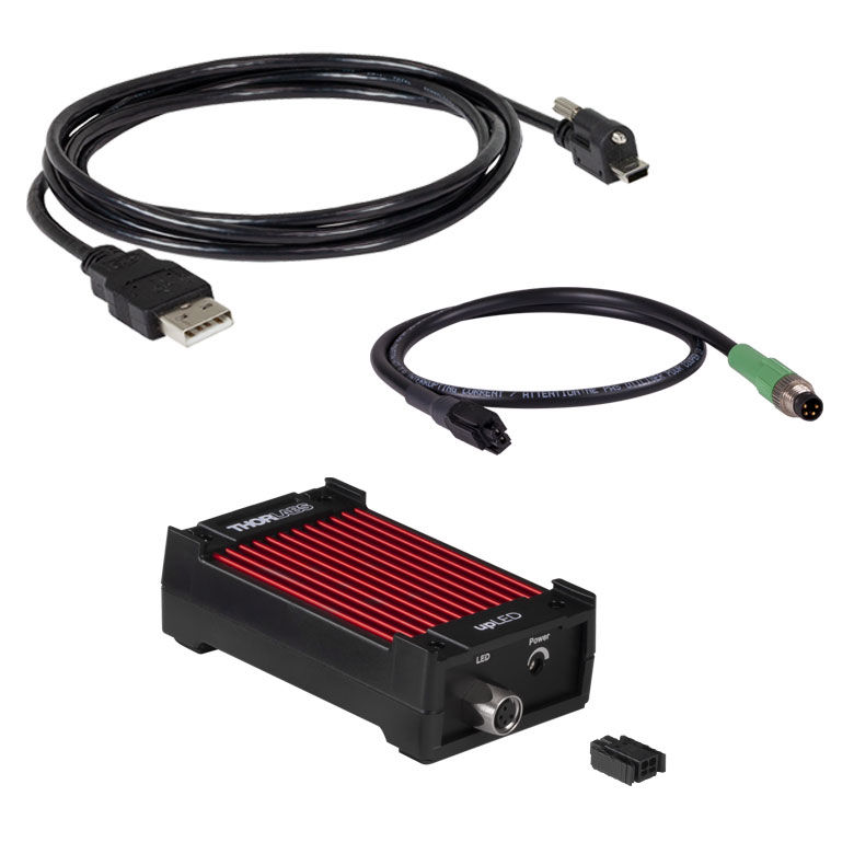
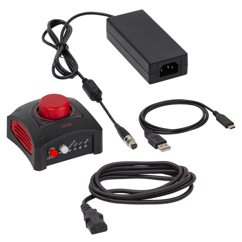
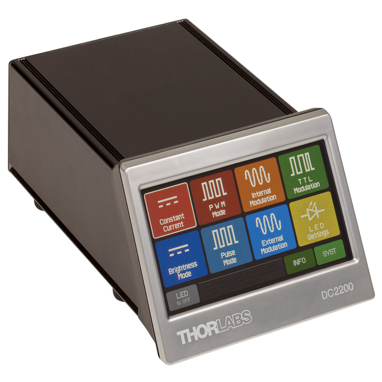
| Compatible Drivers | LEDD1B | UPLEDa | DC40a | DC2200a | DC4100a,b | DC4104a,b |
|---|---|---|---|---|---|---|
| Click Photos to Enlarge | 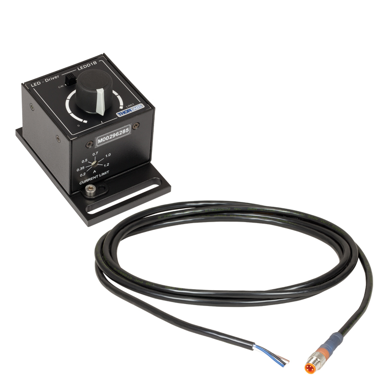 |
 |
 |
 |
 |
 |
| LED Driver Current Output (Max)c | 1.2 A | 1.2 A | 4.0 Ad | LED1 Terminal: 10.0 A LED2 Terminal: 2.0 Ae |
1.0 A per Channel | 1.0 A per Channel |
| LED Driver Forward Voltage (Max)f | 12 V | 8 V | 14.0 Vd | 50 V | 5 V | 5 V |
| Modulation Frequency Using External Input (Max) | 5 kHzg | - | 5 kHzg | 250 kHzg,h,i,j | 100 kHzg,h,j (Simultaneous Across all Channels) |
100 kHzg,h,j (Independently Controlled Channels) |
| External Control Interface(s) | Analog (BNC) | USB 2.0 | USB 2.0, TTL, and Analog (BNC) | USB 2.0 and Analog (BNC) | USB 2.0 and Analog (BNC) | USB 2.0 and Analog (8-Pin) |
| Main Driver Features | Very Compact Footprint 60 mm x 73 mm x 104 mm (W x H x D) |
USB-Controlled | Driver Current Up to 4.0 A, Manual and USB-Controlled |
Touchscreen Interface with Internal and External Options for Pulsed and Modulated LED Operation | 4 Channelsb | 4 Channelsb |
| EEPROM Compatible: Reads Out LED Data for LED Settings | - | |||||
| LCD Display | - | - | - |
LED SELECTION GUIDE
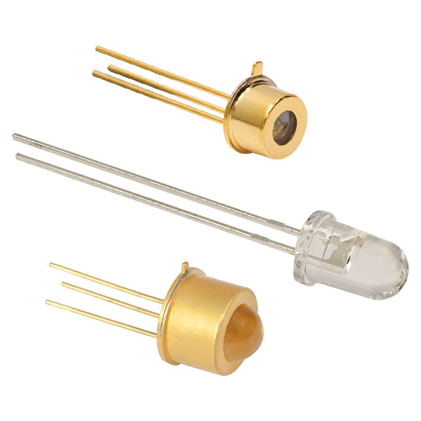
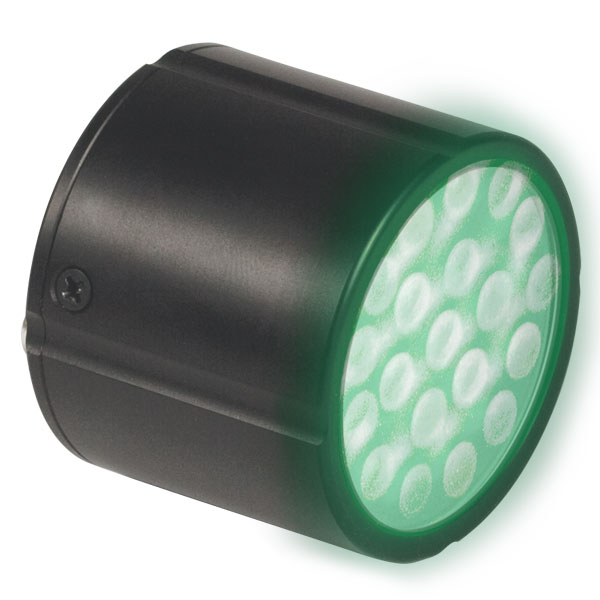
This tab includes all LEDs sold by Thorlabs. Click on More [+] to view all available wavelengths for each type of LED pictured below.
| Light Emitting Diode (LED) Selection Guide | ||||||
|---|---|---|---|---|---|---|
| Click Photo to Enlarge (Representative; Not to Scale) |
 |
 |
 |
 |
 |
 |
| Type | Unmounted LEDs | Pigtailed LEDs | LEDs in SMT Packages |
LED Arrays | LED Ring Light | Cage-Compatible Diffuse Backlight LED |
| Light Emitting Diode (LED) Selection Guide | ||||||
|---|---|---|---|---|---|---|
| Click Photo to Enlarge (Representative; Not to Scale) |
 |
 |
 |
 |
 |
 |
| Type | PCB- Mounted LEDs |
Heatsink- Mounted LEDs |
Collimated LEDs for Microscopyb | Fiber- Coupled LEDsc |
High-Power LEDs for Microscopy | Multi-Wavelength LED Source Optionsd |
Fiber-Coupled LEDs

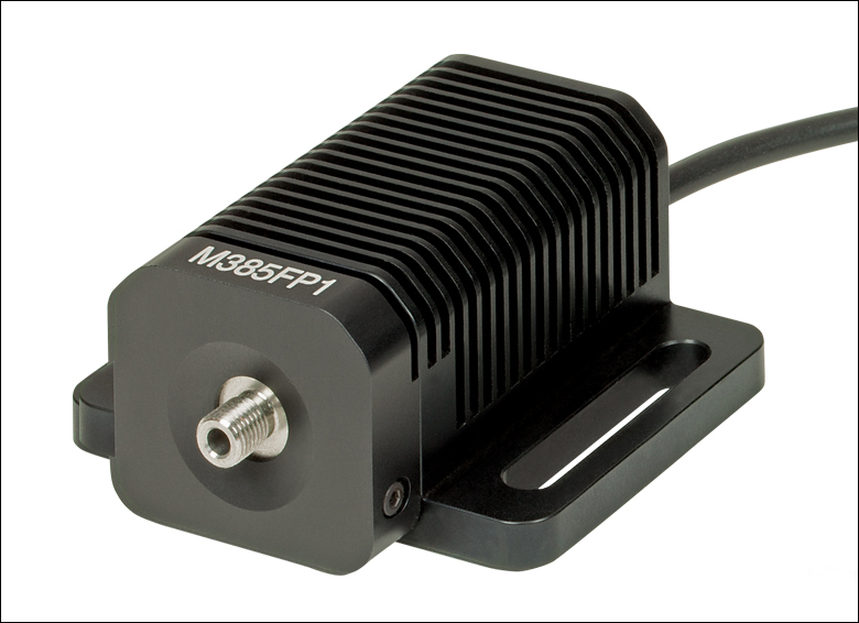
Click to Enlarge
M365FP1, M385FP1, M395FP1, M405FP1, and M660FP1 are each mounted to a 50 mm long heat sink.
- Integrated EEPROM for Automated LED Settings with Compatible Thorlabs Controllers
- Long Lifetimes >10 000 Hours (Except M280F5, M325F4, M340F4, and M660FP1; See Specs Tab for Details)
- Output can be Modulated with Suitable Controller (See LED Drivers Tab)
- Stable Output Intensity by Optimized Thermal Management
- Accepts SMA Fiber Connector
These fiber-coupled LEDs each consist of an LED mounted to a heat sink with an SMA fiber bulkhead. They can be easily integrated into an optical setup using one of our SMA-terminated multimode fiber patch cables. When the patch cable is connected to the SMA bulkhead on the LED housing, the LED will be butt-coupled to the SMA fiber connector. Hybrid patch cables can be used to transition from an SMA connector to an FC/PC connector, ferrule end, or bare fiber. For compatible drivers to power these LEDs, please see the LED Drivers tab. Please note that the minimum output powers specified below apply when the LED is used with a Ø400 µm core multimode fiber patch cable.
For applications where a hybrid patch cable is not practical, we can configure these fiber-coupled LEDs with FC/PC bulkheads; contact Tech Support for details.
Part Number | Description | Price | Availability |
|---|---|---|---|
M280F5 | 280 nm, 0.5 mW (Min) Fiber-Coupled LED, 500 mA, SMA | $480.70 | Today |
M310F1 | 308 nm, 300 µW (Min) Fiber-Coupled LED, 600 mA, SMA | $661.11 | Today |
M325F4 | 325 nm, 260 µW (Min) Fiber-Coupled LED, 600 mA, SMA | $977.02 | Lead Time |
M340F4 | 340 nm, 0.45 mW (Min) Fiber-Coupled LED, 600 mA, SMA | $467.02 | Today |
M365FP1 | 365 nm, 9.8 mW (Min) Fiber-Coupled LED, 1400 mA, SMA | $727.02 | Today |
M375F3 | 375 nm, 3.2 mW (Min) Fiber-Coupled LED, 500 mA, SMA | $531.00 | Today |
M385FP1 | 385 nm, 18 mW (Min) Fiber-Coupled LED, 1400 mA, SMA | $727.02 | Today |
M395F3 | 395 nm, 4.8 mW (Min) Fiber-Coupled LED, 500 mA, SMA | $417.16 | Today |
M395FP1 | 395 nm, 20.1 mW (Min) Fiber-Coupled LED, 1400 mA, SMA | $634.16 | Today |
M405F3 | 405 nm, 3.0 mW (Min) Fiber-Coupled LED, 500 mA, SMA | $531.00 | Today |
M405FP1 | 405 nm, 19.3 mW (Min) Fiber-Coupled LED, 1400 mA, SMA | $727.02 | Today |
M415F3 | 415 nm, 14.4 mW (Min) Fiber-Coupled LED, 1500 mA, SMA | $471.67 | Today |
M430F1 | 430 nm, 5.3 mW (Min) Fiber-Coupled LED, 500 mA, SMA | $257.17 | Today |
M455F3 | 455 nm, 17 mW (Min) Fiber-Coupled LED, 1000 mA, SMA | $469.25 | Today |
M470F4 | 470 nm, 14 mW (Min) Fiber-Coupled LED, 1000 mA, SMA | $296.82 | Today |
M490F4 | 490 nm, 1.8 mW (Min) Fiber-Coupled LED, 350 mA, SMA | $352.34 | Today |
M505F3 | 505 nm, 8.5 mW (Min) Fiber-Coupled LED, 1000 mA, SMA | $436.74 | Today |
M530F3 | 530 nm, 6.8 mW (Min) Fiber-Coupled LED, 1000 mA, SMA | $450.00 | Today |
MINTF4 | 554 nm, 21 mW (Min) Fiber-Coupled LED, 1225 mA, SMA | $582.32 | Today |
M565F3 | 565 nm, 9.9 mW (Min) Fiber-Coupled LED, 700 mA, SMA | $510.10 | Today |
M590F3 | 590 nm, 3.3 mW (Min) Fiber-Coupled LED, 1000 mA, SMA | $511.08 | Today |
M595F2 | 595 nm, 8.7 mW (Min) Fiber-Coupled LED, 1000 mA, SMA | $449.03 | Today |
M617F2 | 617 nm, 10.2 mW (Min) Fiber-Coupled LED, 1000 mA, SMA | $449.03 | Lead Time |
M625F2 | 625 nm, 13.2 mW (Min) Fiber-Coupled LED, 1000 mA, SMA | $449.03 | Today |
M660FP1 | 660 nm, 10.6 mW (Min) Fiber-Coupled LED, 1400 mA, SMA | $494.12 | Today |
M680F4 | 680 nm, 5.9 mW (Min) Fiber-Coupled LED, 600 mA, SMA | $289.19 | Today |
M700F4 | 700 nm, 4.0 mW (Min) Fiber-Coupled LED, 500 mA, SMA | $311.69 | Lead Time |
M740F2 | 740 nm, 4.1 mW (Min) Fiber-Coupled LED, 800 mA, SMA | $531.00 | Today |
M780F2 | 780 nm, 5.5 mW (Min) Fiber-Coupled LED, 800 mA, SMA | $457.35 | Today |
M810F3 | 810 nm, 12.7 mW (Min) Fiber-Coupled LED, 1000 mA, SMA | $328.03 | Today |
M850F3 | 850 nm, 8.6 mW (Min) Fiber-Coupled LED, 1000 mA, SMA | $332.64 | Today |
M880F2 | 880 nm, 2.7 mW (Min) Fiber-Coupled LED, 1000 mA, SMA | $457.35 | Today |
M940F3 | 940 nm, 10 mW (Min) Fiber-Coupled LED, 1000 mA, SMA | $452.29 | Today |
M970F3 | 970 nm, 5.9 mW (Min) Fiber-Coupled LED, 1000 mA, SMA | $401.80 | Today |
M1050F3 | 1050 nm, 2.3 mW (Min) Fiber-Coupled LED, 600 mA, SMA | $634.72 | Today |
M1100F1 | 1100 nm, 2.0 mW (Min), Fiber-Coupled LED, 1000 mA, SMA | $379.99 | Today |
M1200F1 | 1200 nm, 1.6 mW (Min) Fiber-Coupled LED, 1000 mA, SMA | $382.35 | Lead Time |
M1300F1 | 1300 nm, 1.42 mW (Min), Fiber-Coupled LED, 1000 mA, SMA | $386.39 | Today |
M1450F1 | 1450 nm, 0.86 mW (Min), Fiber-Coupled LED, 1000 mA, SMA | $380.47 | Today |
MBB1F1 | Broadband (470 - 850 nm), 0.8 mW (Min) Fiber-Coupled LED, 500 mA, SMA | $812.53 | Today |
MCWHF2 | 6200 K, 21.5 mW (Min) Fiber-Coupled LED, 1000 mA, SMA | $449.03 | Today |
MWWHF2 | 4000 K, 16.3 mW (Min) Fiber-Coupled LED, 1000 mA, SMA | $449.03 | Today |
Mounted LED Mating Connector

- Female 4-Pin Pico (M8) Receptacle
- M8 x 1 Thread for Connection to Mounted LED Power Cable
- M8 x 0.5 Panel-Mount Thread for Custom Housings
- 0.5 m Long, 24 AWG Wires
- IP 67 and NEMA 6P Rated
The CON8ML-4 connector can be used to mate mounted LEDs featured on this page to user-supplied power supplies. We also offer a male 4-Pin M8 connector cable (item # CAB-LEDD1).
| Pin | Color | Specification |  |
|---|---|---|---|
| 1 | Brown | LED Anode | |
| 2 | White | LED Cathode | |
| 3 | Black | EEPROM GND | |
| 4 | Blue | EEPROM IO |

CON8ML-4 Shown Connected to the 4-Pin M8 Plug of Mounted LED
Part Number | Description | Price | Availability |
|---|---|---|---|
CON8ML-4 | 4-Pin Female Mating Connector for Mounted LEDs | $36.54 | Today |