High-Speed Focusers
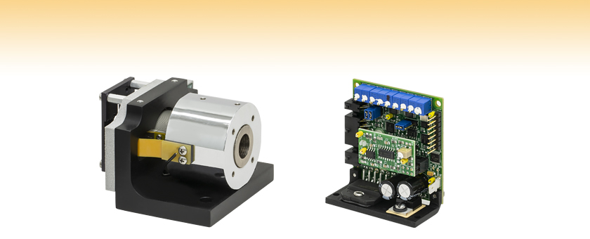
- Z-Axis Translation at High Frequency
- Dynamic Focusing for Scanning Systems
- Optional Bonded Lens for UV or Nd:YAG Lasers
BLINK
High-Speed Translator
US Patent 11,090,761
Included Servo Driver

Please Wait
Large-Volume Orders
For orders where a large quantity of an item is purchased and the delivery of that item is scheduled with our production (i.e., not taken directly from inventory), Thorlabs passes on to the customer the cost savings associated with planned production of high volumes of that item. Since the volume and planned production are key to realizing the cost savings, we ask that you contact us to obtain volume pricing.
Additional requests can include custom optic sizes and coatings, specialized tuning, and variable cable options.
| Key Specificationsa | |||
|---|---|---|---|
| Item # | BLINK | BLINK-Y1 | BLINK-Y3 |
| Included Lens | None | Nd:YAG | 355 nm |
| Lens Coating | N/A | 1000 - 1550 nm | 240 - 400 nm |
| Lens Size | N/A | Ø12.7 mm | |
| Travel Range | 13 mm | ||
| Servo Bandwidth | >500 Hz | ||
| System Resolution | 200 nm | ||
| System Repeatability | 800 nm | ||
Isotropic Imaging Across Spatial Scales with Axially Swept Light-Sheet Microscopy
K. M. Dean, T Chakraborty, S. Daetwyler, J. Lin, G. Garrelts, O. M'Saad, H. T. Mekbib, F. F. Voigt, M. Schaettin, E. T. Stoeckli, F. Helmchen, J. Bewersdorf, and R. Fiolka
Features
- Dynamic Z-Axis Scanning
- Provides Focal Correction for 2-Axis Scanning Systems
- Capable of Continuous Operation up to 157 Hz
- Non-Contact Air Bearings with Voice-Coil Driver
- Servo Driver Included
- >500 Hz Servo Bandwidth
- Power Supply, Command Cables, and Power Cables Available Separately
The BLINK High-Speed Focuser (US Patent 11,090,761) is designed to dynamically map a focal correction onto the laser beam as a function of its XY position. By translating a focusing lens at high frequencies along the optical axis, the focuser adjusts the effective focal point of a galvo scanning system to account for large angles or arbitrary surfaces. When used as the focusing element of a post-objective scanning system, BLINK allows high-speed processing of large planar samples and 3D contoured samples. See the 2-Axis vs. 3-Axis tab for more information.
Focusers are available with or without a bonded lens. The lens can be coated for UV (355 nm) or Nd:YAG (1064 nm) lasers. Please note that a suitable air supply is needed to operate the BLINK focusers. Attempting to operate the focuser without an air supply may damage the bearing surfaces and degrade the performance.
Two compatible ±15 V power supplies (either open frame or enclosed) and command cable(s) are sold separately below. For a list of which power supplies and cables to use with which focusers, see the Focuser Compatibility tab.
| Item # | BLINK | BLINK-Y1 | BLINK-Y3 |
|---|---|---|---|
| Included Lens | None | Nd:YAG | 355 nm |
| Coating Wavelength Range | N/A | 1000 - 1550 nm | 245 - 400 nm |
| Effective Focal Length | N/A | -75 mm | |
| Size | See Footnote a | Ø12.7 mm | |
| Clear Aperture | See Footnote b | Ø12.4 mm | |
| Mass | N/A | 2 g | |
| Scanner | |||
| Travel Range | 13 mm | ||
| Servo Bandwidth | >500 Hzc | ||
| Force Constant (K) | 6.1 N/Amp | ||
| Coil Resistance | 4.5 Ω | ||
| Position Detector Resolution | 0.2 nm | ||
| System Resolution | 200 nm | ||
| System Repeatability | 800 nm | ||
| Environmental | |||
| Unit Mass | 540 g | ||
| Air Supply Cleanliness | Class 3 or Better | ||
| Air Supply Pressure | 60 - 90 PSI | ||
| Air Supply Flow Rate | <2.5 LPM @ 80 PSI | ||
| Servo Amplifier Specsa | |
|---|---|
| Inputs | |
| Command Input Range | ±5 V |
| Position Input Scale Factor | 0.77 V/mm |
| Command Input Impedance | 400 kΩ (Differential) 200 kΩ (Single Ended) |
| Position Offset Range | ±0.25 V |
| External Enable | TTL (Low: Disable Drive) |
| Diagnostic Outputs | |
| Servo Ready | TTL |
| Position | 0.77 V/mm |
| Position Error | 0.77 V/mm |
| Velocity | Analog (Reference Only) |
| AGC Voltage | Analog (DC) |
| Coil Current | 1 V/A |
| Analog Output Impedance | Unbuffered |
| Power Supply (Not Included) | |
| Input Voltage | ±15 VDC <100 mV Ripple <0.5% DC to 30 MHz Noise |
| Maximum Drive Current Limit | 3 A (RMS); 10 A (Peak) |
| Quiescent Current | 220 mA (Servo Enabled, Galvo at Rest) |
| Gain Drift | Up to 20 ppm/°C |
| General Specs | |
| Operating Temperature | 0 to 45 °C (With Appropriate Cooling) |
| Storage Temperature | -10 to 60 °C |
| Dimensions | 2.38" x 2.22" x 1.06" (60.5 mm x 56.4 mm x 27.0 mm) |
| Mass (Weight) | 49 g (1.7 oz) |
Dynamic Performance for a 1.0 mm Stroke Reference Move
| Frequency | Peak Acceleration | Peak Current | Average Power |
|---|---|---|---|
| Bonded Lens | |||
| 100 Hz | 197 m/s2 (20g) | 1.0 A | 2.3 W |
| 125 Hz | 308 m/s2 (31g) | 1.4 A | 4.4 W |
| 141 Hz | 392 m/s2 (40g) | 1.8 A | 7.3 W |
| 157 Hz | 487 m/s2 (50g) | 2.2 A | 11.1 W |
| Removable Lens | |||
| 100 Hz | 197 m/s2 (20g) | 1.1 A | 2.7 W |
| 125 Hz | 308 m/s2 (31g) | 1.5 A | 5.2 W |
| 141 Hz | 392 m/s2 (40g) | 2.0 A | 8.6 W |
| 157 Hz | 487 m/s2 (50g) | 2.4 A | 13.2 W |
GPWR15 Power Supply Unit Specs
| Parameter | Value |
|---|---|
| Input | 100 - 120 VAC or 220 - 240 VAC |
| Output | ±15 V at 5 A (150 W Max Power) |
| Operating Temperature | 0 to 50 °C |
| Dimensions | 14.0" x 4.9" x 3.5" (356 mm x 124 mm x 90 mm) |
GPS011 Series Linear Power Supply Unit Specs
| Parameter | Value |
|---|---|
| Switchable Input | 100 VAC 50 or 60 Hz 115 VAC 60 Hz 230 VAC 50 Hz |
| Output | ±15 VDC 3.0 A /0.1 A, 1.4/6.3 msec (Max Duty Cycle)a |
| Operating Temperature | 5 to 40 °C |
| Dimensions | 179 mm x 274 mm (Max) x 122 mm (7.05" x 10.79" x 4.8") |
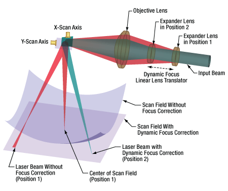
Click to Enlarge
Diagram Illustrating Dynamic Focusing to Achieve a Flat Field in Our XG300 Series and DCB320-Y1 Three-Axis Galvo Scan Heads
In a typical two axis laser scanning system, a collimated beam is reflected by the X and Y axis scanning mirrors before entering the focusing (objective) lens. The lens focuses the beam on the work surface. Rotation of the X and Y mirrors causes movement of the focused spot within a flat field. The size of the spot and the size of the field are determined by the lens (and other factors). This configuration is known as a pre-objective scanning system because the laser strikes the scanning mirrors before the focusing (objective) lens. An f-theta lens is a common choice for the lens in this configuration.
The architecture works well as long as the beam diameter and field size are relatively small. For example, applications using beam diameters less than 20 mm and field sizes less than 300 mm are well suited to Z-axis pre-objective scanning.
As the field size requirements grow, larger scan mirrors and laser beam diameters are needed to maintain a numerical aperture (NA) consistent with a small focused spot. F-theta scan lenses for these large laser beams would be big, costly, and impractical. For this reason, a 3-axis scanning solution should be considered.
In a 3-axis scanning system, as shown in the figure to the right, the XY mirrors are placed after the final focusing lens, and hence they are referred to as a post-objective scanning system. Since the laser beam does not move on the objective lens, the lens does not need to be very large; however, this arrangement does not create a flat field. To achieve a flat field, a third axis (Z-axis) of motion is introduced in the form of a linear lens translator.
The typical laser system uses a telescope to expand the laser beam to a diameter consistent with the required NA. The distance between the telescope input lens and objective lens determines the focal distance of the system. By mounting the input lens on a linear lens translator (the third axis), we gain dynamic control over the focal distance. See the diagram to the right for details.
By coordinating the motion of the linear lens translator with the rotation of the X and Y scanning mirrors, we achieve a focused laser spot throughout a flat field. Alternatively, the same configuration can be used to scan a three-dimensional surface. In this scenario, the Z-axis position is an arbitrary function of the X and Y galvo mirror positions, enabling the system to scan complex geometries.
The table below illustrates how to assemble a focuser system. After picking the focuser needed, choose the applicable power supply and cable set to match. Open frame power supplies require the cables to be soldered into the system, while enclosed power supplies allow the cables to directly connect to the system. A user-supplied controller will also be needed for this system.
| Z-Axis Focusing Module | ||
|---|---|---|
| Z-Axis Focusing Module | Compatible Power Source (Supports up to Two Axes) |
Compatible Cable Set (Choose One Per Axis) |
| BLINK, BLINK-Y1, BLINK-Y3 | GPWR15 Open Frame Power Supplya | CBLS2F |
| GPS011 Series Enclosed Power Supplyb | CBLS2P | |
| Posted Comments: | |
Alexander Voronov
(posted 2023-05-10 17:29:25.233) I would like to use this unit for focus adjustment (laser scribing application). In the application the lens would move with ~40Hz frequency. In addition to z-motion, I expect, there would be undesirable x,y motion. I can compensate repeatable errors. But how much is the random (unrepeatable error ) x,y motion of the lens? jdelia
(posted 2023-05-24 08:51:31.0) Thank you for contacting Thorlabs. There really should not be much, if any, motion in the XY direction from the air bearing. By design, the air bearing should be held in a consistent position. If any non-repeatable deviation is observed by the end user, we would suspect that there is an issue with the air supply or debris in the air lines that is causing insufficient or unsteady airflow. I have reached out to you directly to further discuss your application. Mostafa Aakhte
(posted 2022-08-08 09:07:21.937) Is it possible to gather information regarding the position of the voice coil during motion? or is there an encoder around the voice coil? cdolbashian
(posted 2022-09-16 09:26:17.0) Thank you for reaching out to us regarding this inquiry. There is not an encoder, though it is possible to gather positional information by using the diagnostic connection port. Additional info can be found in the servo amplifier manual. I have reached out to you to discuss this further. Weijan Zong
(posted 2021-09-04 13:29:37.737) Can this z-focusing device (BLINK) stay in a certain focus as demond, or it has be be scanning? YLohia
(posted 2021-09-08 01:35:24.0) The unit can be “parked” at a specific location. You would want to do this for the drill mode, where you want to hold focus at a specific point for your laser to do some processing and then move it to a different point afterwards. You can put any arbitrary signal into this that would suit the customer’s requirements, similar to a galvo. The QD-2000 is a servo controller that tries to match the galvos position signal with the command input signal, so will try and have that match whether the signal is moving in a sine wave, stopped and parked, a triangle wave, or anywhere in between. This could be driven off any analog function generator or DAC that you're familiar with that is able to generate what you're looking for. |

- Dynamic Z-Axis Scanning
- Provides Focal Correction for 2-Axis Scanning Systems
- Mounting Bracket Included
The BLINK High-Speed Focuser (US Patent 11,090,761) provides high-frequency, high-precision Z-axis translation in order to dynamically map a focal correction onto a laser beam. When used as part of a galvo scanning system, the focuser adjusts the system's effective focal point to account for large angles or arbitrary surfaces at the output. BLINK also allows high-speed processing of large planar samples and 3D contoured samples when it is used as the focusing element of a post-objective scanning system. Focusers are available without a bonded lens, or with a bonded lens for either Nd:YAG or 355 nm lasers.
BLINK combines an air bearing guideway with direct voice-coil drive, resulting in a very compact, high-performance focuser. It is capable of continuous operation with a 157 Hz sine wave, and its ultra low moving mass minimizes reaction forces. With only one moving part, BLINK offers exceptional reliability and service life compared to traditional taut band actuators.
The focuser includes an aluminum mounting bracket with two through holes for 1/4"-20 (M6) cap screws. Four M3 tapped mounting holes are located on the top of the unit (two on the mounting bracket and two on the cylindrical lens housing). Four M3 tapped holes around the aperture are spaced 0.92" apart for custom mounting applications.

- GPWR15 Power Supply: ±15 V Power Supply for Single- and Dual-Axis Systems; One Supply Can Power up to Two Galvos
- BLINK Focusers
- QS, SS, and SP Series VantagePro® Galvanometer Scanners
- XG Series Scan Heads
- GPWR15 Power Supply Specs:
- Open Frame Requires Cables to be Soldered In
- Input: 100-120 or 220-240 VAC
- Output: ±15 V @ 5 A (150 W Max Power)
- Operating Temperature: 0 to 50 °C
- Dimensions: 14.0" x 4.9" x 3.5" (356 mm x 124 mm x 90 mm)
- CBLS2F: Command and Power Cables for QS7 and QS10 Series Galvanometer Scanners and BLINK High-Speed Focusers (One Set Required per Axis)
The GPWR15 Power Supply is a low noise, linear supply designed to minimize electrical interference for maximum system resolution. The compatible systems include the BLINK Focusers, the XG Series Scan Heads, and the QS, SS, and SP Series Galvanometers Scanners. The GPWR15 power supply delivers ±15 VDC at 5 A and is configured to accept a mains voltage of 100 - 120 or 220 - 240 VAC. It has an open frame, allowing the user to solder the compatible power cable into the system.
The CBLS2F Command and Power Cable Set can be used to connect the GPWR15 Power Supply to the BLINK high speed focuser or the QS7/10 series galvo scanners. The power cable has a four pin connector on one end for compatibility with the BLINK focusers and three bare wires for soldering to the GPWR15 power supply on the other end. The command cable has a two pin connector on one end for compatibility with the BLINK focusers and three bare wires for soldering to a user-supplied controller on the other end.

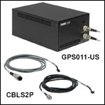
- GPS011 Series: ±15 V Power Supply for Single- and Dual-Axis Systems; One Supply Can Power up to Two Galvos
- BLINK Focusers
- QS7, QS10, QS15, and QS20 Series VantagePro® Galvanometer Scanners
- XG Series Scan Heads
- GPS011 Series Specs:
- Enlcosed Unit Allows Cables to Directly Connect to the System
- Input: 100 VAC / 50 or 60 Hz, 115 VAC / 60 Hz, 230 VAC / 50 Hz
- Output: ±15 V @ 3 A
- Operating Temperature: 5 to 40 °C
- Dimensions: 7.05" x 10.79" x 4.8" (179 mm x 274 mm (Max) x 122 mm)
- CBLS2P: Command and Power Cable Set for BLINK High-Speed Focusers and QS7/10 Scanning Galvanometer Systems
The GPS011 Series Power Supplies are low-noise, linear supplies designed to minimize electrical interference for maximum system resolution for 1D and 2D galvanometer systems. The compatible systems include the BLINK Focusers, QS7, QS10, QS15, and QS20 Series Galvanometers Scanners, and the XG Series Scan Heads. The GPS011 series power supplies deliver ±15 VDC at 3 A and are configured to accept a mains voltage of 115 VAC (for GPS011-US), 230 VAC (for GPS011-EC), or 100 VAC (for GPS011-JP). The GPS011 units are enclosed, allowing for direct connection with the compatible power cable without soldering.
Please note that the GPS011 series power supplies are insufficient for driving the QS30/45 scanning galvanometer systems.
The CBLS2P Power and Command Cable Set can be used to connect the GPS011 series galvo system linear power supplies to the BLINK high speed focuser or the QS7/10 series galvo scanners. The power cable has a three-pin circular connector on one end for compatibility with the GPS011 series power supplies and a four pin connector on the other end for compatibility with the BLINK focusers and QS7/10 galvos. The command cable has a BNC connector on one end for compatability with a user-supplied controller and a two pin connector on the other end for compatibility with the BLINK focusers and QS7/10 galvos.
 Products Home


 Zoom
Zoom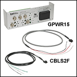
 High-Speed Focusers