 Products Home / Optical Systems / Galvanometers / Single-Axis VantagePro® Scanning Galvanometer Systems
Single-Axis VantagePro® Scanning Galvanometer Systems
- ±15°, ±20°, and ±22.5° Scan Angles and Beam Diameters up to 45 mm
- Choice of Broadband Protected Silver or Mirror Coatings for 355 and 1064 nm
- Easy to Integrate with OEM Systems
- Analog Control Electronics
Servo Driver Included with
Galvanometer Scanners for
Ø7 or Ø10 mm Beams
QS10Y-Y3
Vertical Mirror for Ø10 mm Beams, Dielectric Nd:YAG Coating
Servo Driver Included with
Galvanometer Scanners for Ø4 or Ø5 mm and Ø15 to Ø45 mm Beams
QG4X-AG
Horizontal Mirror for Ø4 mm Beams, Protected Silver Coating
Post-Mounted QS15X-AG Galvo in a QSM2/M Mount with Heat Sink


Please Wait
| Single-Axis Galvanometer Scanner Selection Guide | |||||
|---|---|---|---|---|---|
| Item # Prefix (X- or Y-Axis) |
Mirror Coatingsa | Max Beam Diameter |
Position Detector |
||
| -AG | -Y3 | -Y1 | |||
| QG4(X)(Y) | - | 4 mm | Optical | ||
| QG5(X)(Y) | - | 5 mm | |||
| QS7(X)(Y) | 7 mm | ||||
| QS10(X)(Y) | 10 mm | ||||
| QS15(X)(Y) | 15 mm | ||||
| QS20(X)(Y) | 20 mm | ||||
| QS30(X)(Y) | - | 30 mm | Capacitive | ||
| QS45(X)(Y) | - | 45 mm | |||
| Power Supply & Command Cables | |||||

Large-Volume Orders
For orders where a large quantity of an item is purchased and the delivery of that item is scheduled with our production (i.e., not taken directly from inventory), Thorlabs passes on to the customer the cost savings associated with planned production of high volumes of that item. Since the volume and planned production are key to realizing the cost savings, we ask that you contact us to obtain volume pricing.
Additional requests can include custom optic sizes and coatings, specialized tuning, and variable cable options.

Applications
- Laser Marking
- Additive Manufacturing
- Laser Engraving
- Welding
- Micromachining
- Laser Drilling
- Ablation/Surface Texturing
- Cutting/Scribing
- Laser Scanning Microscopy
- Laser Projection
Demo Units Available
Interested in trying a Single-Axis VantagePro® Scanning Galvanometer System for your application? To request a demo unit, contact us at techsales@thorlabs.com.Features
- Moving Magnet Motor Design for Fast Response from 200 to 1200 µs
- High-Precision Optical or Capacitive Mirror Position Detection (See Table to the Right for Details)
- Three Mirror Coatings Available:
- Custom Protected Silver, 450 nm to 10.6 µm
- Nd:YAG Laser, 3rd Harmonic, 355 nm
- Nd:YAG Laser, 1064 nm
- High Reflectance at 633 nm for Alignment Laser
- Analog PID Control Electronics with Current Damping
- 24" (610 mm) Drive Cable Included
- Power Supply, Command Cables, Power Cables, and Mounts Available Separately
- Additional Custom Coatings Available upon Request (Contact Tech Support for Details)
These high-speed VantagePro® scanning galvanometer mirror positioning systems are designed for integration into OEM or custom laser beam steering applications. Models are available for beam diameters up to 45 mm. Each system includes a single-axis galvo motor with mirror and a matched driver card. Dimensions and mounting features can be accessed by clicking on the red docs icon
(![]() ) next to the Item # below. A compatible ±15 V power supply (either open frame or enclosed), command cable(s), and optional mounts are sold separately below. For a list of which power supplies, cables, and mounts to use with which galvos, see the Galvo Compatibility tab.
) next to the Item # below. A compatible ±15 V power supply (either open frame or enclosed), command cable(s), and optional mounts are sold separately below. For a list of which power supplies, cables, and mounts to use with which galvos, see the Galvo Compatibility tab.
The user must provide a function generator or other analog voltage output device in order to operate the servo drivers. The mirrors are offered with one of three coatings: a custom broadband protected silver coating, a coating for 355 nm, or for 1064 nm, as shown in the table to the right. Additional custom coatings are available upon request. Please contact Tech Support for more details. We also offer dual-axis systems that use the QS series galvos.
Servo Driver Board
These closed-loop servo drivers interpret the signals from the position-detecting system inside the motor and produce the drive voltage required to rotate the mirror to the desired position. High bandwidth ensures that analog command waveforms are followed with speed and accuracy.
Both drivers feature proportional-integral-derivative (PID) servo driver circuits with advanced current damping for high performance. The drivers incorporate low-noise components to maximize the signal-to-noise ratio for better accuracy and low-drift components to reduce the effects of temperature variation. A notch filter is selected and tuned for each unique mirror-galvo combination to maximize system bandwidth for faster, more accurate scanning. These systems are ideal for use in applications including step-and-hold positioning, vector positioning (e.g., laser marking), and raster positioning (printing or scanning laser microscopy).
Servos are optimized for high-speed, precise positioning for all applications. Servos for scanners with 4 or 5 mm and ≥15 mm maximum beam diameters additionally feature dual-output power amplifiers to keep power supply requirements modest for larger motors without sacrificing performance. Servo driver circuits provide soft start/stop operation, open circuit AGC fail, and over/under-voltage protections. Onboard status LEDs indicate servo status and fault conditions and a diagnostic port provides position, velocity, error, and current information. Each driver-galvo-mirror set is tested and tuned to specification. The unique serial number of the galvanometer is noted on its associated driver board. Note that the X and Y drivers are matched to their respective servos and are not interchangeable.
| Galvanometer Scanner Specs | |||||||||
|---|---|---|---|---|---|---|---|---|---|
| Item # Prefix | QG4X QG4Y |
QG5X QG5Y |
QS7X QS7Y |
QS10X QS10Y |
QS15X QS15Y |
QS20X QS20Y |
QS30X QS30Y |
QS45X QS45Y |
|
| Max Beam Diameter | 4 mm | 5 mm | 7 mm | 10 mm | 15 mm | 20 mm | 30 mm | 45 mm | |
| Mirror Substrate | Fused Silica | Silicon Carbide | |||||||
| Step Response Timea (0.4° Opticalb) | 200 µs ± 5% | 250 µs ± 5% | 250 µs | 350 µs | 600 µs | 650 µs | 1200 µs | 1200 µs | |
| Mechanical and Electrical Specs | |||||||||
| Rated Excursionb | ±15° | ±20° | ±22.5° | ||||||
| Rotor Inertial Load |
Recommended | 0.018 g·cm2 | 0.17 g·cm2 | 1.8 g·cm2 | 5.1 g·cm2 | ||||
| Max | 0.09 g·cm2 | 0.85 g·cm2 | 9 g·cm2 | 25 g·cm2 | |||||
| Torque Constant | 29 300 dyne·cm/A | 40 000 dyne·cm/A | 180 000 dyne·cm/A | 280 000 dyne·cm/A | |||||
| Coil Resistance | 3.0 Ω | 1.3 Ω | 3.0 Ω | 5.8 Ω | |||||
| Coil Inductance | 530 µH @ 1 kHz | 76 µH @ 1 kHz | 530 µH @ 1 kHz | 450 µH @ 1 kHz | |||||
| Position Detector | |||||||||
| Type | Optical | Capacitive | |||||||
| Linearity @ Full Excursion | ≥99.88% | 99.8% @ ±20° | >99.9% | ||||||
| Gain Drift | <30 ppm/°C | 50 ppm/°C | 50 ppm/°C | ||||||
| Offset Drift | <20 µrad/°C | 30 µrad/°C | 40 µrad/°C | ||||||
| Repeatability | ≤20 µrad | 10 µrad | 15 µrad | ||||||
| Output Signal (Typ.) |
Differential Modeb | 6 µA/° | 7.1 µA/° | 40 µA/° | |||||
| Common Mode | 300 µA | 385 µA | 2100 µA | ||||||
| Supply Current | 15 - 30 mA | 30 - 40 mA | 10 - 20 mA | ||||||
| General Specs | |||||||||
| Operating Temperature | 0 to 40 °C (Non-Condensing) | ||||||||
| Storage Temperature | -10 to 50 °C | ||||||||
| Servo Shaft Size | Ø9.47 mm x 35.7 mm | Ø14 mm x 26.3 mm | Ø22 mm x 50 mm | Ø30.5 mm x 30 mm | |||||
| Mass (Galvo Only) | 23 g | 36 g | 128 g | 306 g | |||||
| Mirror Coating Specs | |||
|---|---|---|---|
| Item # Suffix | -AG | -Y3 | -Y1 |
| Coating Type | Custom Protected Silver | Hard Dielectric for Nd:YAG Laser 3rd Harmonic |
Hard Dielectric for Nd:YAG Laser Fundamental |
| Absolute Reflectance |
≥92% (450 - 500 nm) ≥94.5% (500 - 2000 nm) ≥98% (2 - 10.6 µm) |
≥99% (355 nm) ≥80% (633 nm) |
≥98% (1064 nm) ≥80% (633 nm) |
| Surface Quality (Scratch-Dig) |
40-20 | 20-10 | 40-20 |
| Servo Amplifier Specsa | ||||
|---|---|---|---|---|
| Item # Prefix | QG4(X)(Y) | QG5(X)(Y) | QS7(X)(Y) QS10(X)(Y) |
QS15(X)(Y) QS20(X)(Y) QS30(X)(Y) QS45(X)(Y) |
| Inputs | ||||
| Command Input Range | ±10 V | ±5 V | ||
| Position Input Scale Factorb | 0.67 V/° | 0.50 V/° | 0.22 V/° | |
| Command Input Impedance | 20 kΩ ± 1% (Differential) 10 kΩ ± 1% (Single Ended) |
400 kΩ (Differential) 200 kΩ (Single Ended) |
20 kΩ ± 1% (Differential) 10 kΩ ± 1% (Single Ended) |
|
| Position Offset Range | ±0.25 V | |||
| External Enable | See Footnote c for Details | TTL (Low: Disable Drive) | See Footnote c for Details | |
| Diagnostic Outputs | ||||
| Servo Ready | 12 V | TTL | 12 V | |
| Positionb | 0.33 V/° | 0.50 V/° | 0.22 V/° | |
| Position Errorb | 0.33V/° | 0.50 V/° | 0.22 V/° | |
| Velocity | Analog (Reference Only) | |||
| AGC Voltage | Analog (DC) | |||
| Coil Current | 1 V/A | |||
| Analog Output Impedance | 1 kΩ ± 1% (For All Outputs) | Unbuffered | 1 kΩ ± 1% (For All Outputs) | |
| Power Supply (Not Included) | ||||
| Input Voltage | ±15 to ±24 VDC <100 mV Ripple <0.5% DC to 30 MHz Noise |
±15 VDC <100 mV Ripple <0.5% DC to 30 MHz Noise |
±15 to ±24 VDC <100 mV Ripple <0.5% DC to 30 MHz Noise |
|
| Maximum Drive Current Limit | 2 A (RMS); 6 A (Peak) | 3 A (RMS); 10 A (Peak) | 4 A (RMS); 10 A (Peak) | |
| Quiescent Current | 220 mA (Servo Enabled, Galvo at Rest) | |||
| Gain Drift | Up to 20 ppm/°C | |||
| Offset Drift | Up to 26 µrad/°C | Up to 30 µrad/°C | ||
| General Specs | ||||
| Operating Temperature | 0 to 45 °C (With Appropriate Cooling) | |||
| Storage Temperature | -10 to 60 °C | |||
| Dimensions | 2.38" x 2.13" x 1.06" (60.5 mm x 54.1 mm x 27.0 mm) |
2.38" x 2.22" x 1.06" (60.5 mm x 56.4 mm x 27.0 mm) |
2.38" x 2.13" x 1.06" (60.5 mm x 54.1 mm x 27.0 mm) |
|
| Mass (Weight) | 74 g (2.6 oz) | 49 g (1.7 oz) | 74 g (2.6 oz) | |

Galvanometer Motor/Mirror Assembly
The system consists of a galvanometer-based scanning motor with a mirror mounted on the shaft and a detector that provides positional feedback to the control board. The moving magnet design for the QS and QG series of galvanometer motors were chosen over a stationary magnet and rotating coil design in order to provide the fastest response times and the highest system resonant frequency. The position of the mirror is encoded using an optical or capacitive sensing system located inside of the motor housing.
Due to the large angular acceleration of the rotation shaft, the size, shape, and inertia of the mirrors become significant factors in the design of high-performance galvanometer systems. Furthermore, the mirror must remain rigid (flat) even when subjected to large accelerations. All these factors have been precisely balanced in our systems in order to match the characteristics of the motor and maximize performance.
The optics are secured to the motor/mirror assembly by a flexure clamp. The positions of the optical mount are set at the factory and should not be changed by the user.
System Operation
The servo driver must be connected to a DC power supply, the galvanometer motor, and an input command voltage source (the monitoring connection is optional). For continuous scanning applications, a function generator with a sine wave output is sufficient for scanning the mirror over its entire range. For more complex scanning patterns, a programmable voltage source such as a DAQ card can be used. User-generated motion trajectories with smooth acceleration profiles are preferred; uncontrolled steps should be avoided if possible. Please note that these systems do not include a power supply (sold separately below), function generator, or DAQ card. The drivers below are factory configured for a 0.22 V/° (QS series), 0.5 V/° (QG5 series), or 0.67 V/° (QG4 series) ratio between the input voltage and mirror position, as well as an input voltage of ±5 (QS series) or ±10 VDC (QG series). Drivers configured for 0.44 V/° and ±10 VDC are available upon request; please contact Tech Support. The control circuit also provides monitoring outputs that allow the user to track the position of the mirror. In addition, voltages proportional to the drive current being supplied to the motor and the difference between the command position and the actual position of the mirror are supplied by the control circuit.
Closed-Loop Mirror Positioning
The angular orientation (position) of the mirror is measured using an optical or capacitive sensing system, which is integrated into the interior of the galvanometer housing, and allows for the closed-loop operation of the galvanometer mirror system.
The table below illustrates how to assemble a galvo system. After picking the galvo needed, choose the applicable power supply and cable set to match. Open frame power supplies require the cables to be soldered into the system, while enclosed power supplies allow the cables to directly connect to the system. A user-supplied controller will also be needed for this system.
| Galvo Compatability | |||
|---|---|---|---|
| Galvo | Compatible Power Supply (Supports up to Two Axes) |
Compatible Cable Set (Choose One Per Axis) |
Compatible Mount (Optional) |
| QG4 or QG5 | GPWR15 Open Frame Power Supplya | CBLS3F | QSM4(/M) |
| GPS011 Series Enclosed Power Supplyb | CBLS3P | ||
| QS7 or QS10 | GPWR15 Open Frame Power Supplya | CBLS2F | QSM1(/M) |
| GPS011 Series Enclosed Power Supplyb | CBLS2P | ||
| QS15 or QS20 | GPWR15 Open Frame Power Supplya | CBLS3F | QSM2(/M) |
| GPS011 Series Enclosed Power Supplyb | CBLS3P | ||
| QS30 or QS45 | GPWR15 Open Frame Power Supplya | CBLS3F | QSM3(/M) |
Components Included with Single-Axis Scanning Galvanometer Systems

Click to Enlarge
Components shipped with QG4 and QG5 series Galvanometers
QG4, QG5, QS15, QS20, QS30, and QS45 Galvanometers
- Galvo Motor with Mounted Mirror
- Class 1 Servo Amplifier
- 24" (61 cm) Cable Assembly (Connects Motor and Servo Amplifier)
- Connector Kit (See the QG4/5 Series Servo Amplifier Manual or the QS15/20/30/45 Series Servo Amplifier Manual)
QS7 and QS10 Galvanometers
- Galvo Motor with Mounted Mirror
- Class 0 Servo Amplifier
- 24" (61 cm) Cable Assembly (Connects Motor and Servo Amplifier)
- Connector Kit (See the QS7/10 Servo Amplifier Manual)
| Posted Comments: | |
Hongrae Kim
(posted 2024-04-29 13:28:32.56) I'm using a galvo mirror from Thorlabs, QS7X-AG, and I found that QS7X-AG has a slight vibration about +- 10 micro radians even when at rest.
I found that the stated repeatability for this model is 10 micro radians according to Thorlabs website.(https://www.thorlabs.com/newgrouppage9.cfm?objectgroup_id=14115&pn=QS7X-AG#14129)
Does the term "repeatability" mean that its vibration is about 10 micro radians?
And is 10 micro radians a minimum value for "repeatability"? (My galvo's vibration is about 20 micro radians. So I wonder whether this value is within an acceptable range...) cdolbashian
(posted 2024-05-06 10:49:41.0) Thank you for reaching out to us with this inquiry. I would not expect you to see such vibrations (corresponding to uV of signal). When we measure stable vibrations in the lab, our measured values are consistently lower. Perhaps this has to do with your power supply. I have contacted you to troubleshoot your issue. WeiChi Hung
(posted 2024-03-14 18:48:08.083) 1. 請問Servo Amplifier Manual 7.3節中J-12區的Pin1-Galvo Position Output 單位及範圍是什麼,以及他數值代表的角度或位置意義是什麼,以及初始狀態時Galvo Position數值為多少?
2. 請問此振鏡是否只能使用Analog Output來控制電壓以控制旋轉角度? cdolbashian
(posted 2024-03-18 11:24:26.0) Thank you for reaching out to us with the following, translated, inquiry:
1. What is the unit and range of Pin1-Galvo Position Output in the J-12 area in Section 7.3 of the Servo Amplifier Manual
2. what is the meaning of the angle or position represented by its value and what is the value of the Galvo Position in the initial state?
4. Can this galvanometer only use Analog Output to control the voltage to control the rotation angle?.
The answers to your questions are as follows:
1. +/-5V with the scaling of 0.22V/°Optical
2. The voltage output of the diagnostic pin is +/-5V corresponding to 0.22V/° optical. The optical angle is twice the mechanical angle (due to the law of reflection, whereas a beam reflecting will have an equal incident and outgoing angle).
The initial state corresponds to 0V. The mirrors are set to a nominal factory set zero position, such that that a beam input parallel to the mounting surface will be reflected and output as a parallel beam which has been turned 90° and displaced vertically, as shown here: https://www.thorlabs.com/_sd.cfm?fileName=MSTN000971-E0W.pdf&partNumber=QS15XY-AG
3. Yes, the galvonometer moves linearly with analog input voltage following the relationship of 0.22V/°
I have contacted you directly with more information here. Byung-Jin Lee
(posted 2023-12-08 15:57:50.31) I have a question about QS30X-Y1 motor. I want to rotate an attachment with an inertial load of about 10g*cm^2 from 0 to 2 degrees quickly and accurately. The input signal is DC, and the increment is basically a square wave, but could be sin or exponential. How fast and accurately can I rotate it using this motor? A delayed or slightly smaller actual motor rotation angle compared to the input signal is not a problem for us as long as it is constant from input to input. ksosnowski
(posted 2023-12-11 10:39:20.0) Thanks for reaching out to Thorlabs. Each galvo driver card is tuned to be specifically paired with the same motor/mirror at all times. A special load like this would require special tuning during production. Since a square wave's rising slope is quite steep, most voltage sources can switch the square wave faster than the galvo driver's max slew rate. When this happens, the galvo will draw the max possible current it can, and will experience increased error while the galvo catches up to the command point. This leads to a constant velocity or triangular wave position output. The choice of waveform and associated slope of the waveform strongly effects whether or not you'll hit a point where your waveform changes voltage faster than the galvo driver can. We do specify a small step response which is limited by the circuit settling time however above 0.4 degrees the magnitude of the command may require enough driving current to place something like 2 degrees at the start of the large signal regime which is slew-limited. Changing the waveform may change the settling time at this magnitude however the performance is in any case still stable and repeatable. Andrew Chuang
(posted 2023-08-22 22:24:47.64) Do you offer longer length cable?
What's the gauge size of the line you are using ? ksosnowski
(posted 2023-09-13 11:05:52.0) Hello Andrew, thanks for reaching out to Thorlabs. Each of the QS series galvos comes with a spare connector kit for creating custom length cables. Longer command cables may pick up additional noise and using too long of a power cable could pose a higher impedance and reduce the supply power. Depending on the noise a filter might be used on the command cable to eliminate this or a higher current power supply may be used to overcome power losses. The power cable uses 24AWG and the command cable uses 22AWG conductors. I have reached out directly to discuss your application in further detail. Andrew Chuang
(posted 2023-03-16 19:55:29.277) Hello...
Is there a manual for GPWR15 ? ksosnowski
(posted 2023-04-03 05:54:39.0) Thanks for reaching out to Thorlabs. As the GPWR15's operating instructions are engraved on the device front panel, we have not traditionally had a manual for this unit. However we are currently working on additional documentation to support this. I have contacted you directly to discuss this application in more detail. Daniel Brown
(posted 2022-12-08 21:11:29.297) In lieu of a manual, could you please also send me a copy of any supporting documentation you have for this galvo and power supply? cdolbashian
(posted 2022-12-15 01:37:27.0) Thank you for reaching out to us with this inquiry. I have contacted you to share what additional supporting documentation we have. Please feel free to click the red "Docs" icon above for item specific manuals. Anthony Notari
(posted 2022-06-16 13:04:17.843) It's difficult to guess which connector does what just by looking at the serving driver board - do you have a very basic schematic that you could send me? Thanks. cdolbashian
(posted 2022-06-17 04:58:13.0) Thank you for contacting us! I have contacted you directly with supporting documentation. 子晗 谢
(posted 2022-05-20 23:19:23.113) Where is Manual (PDF)? cdolbashian
(posted 2022-05-27 12:41:19.0) Thank you for reaching out to us with this inquiry. We are in the process of releasing a manual with explicit operating instructions. I have sent you some supporting documentation in the meantime. ofir kalif
(posted 2021-10-12 23:13:07.867) Hi,
I need a galvo motor like QS20Y-AG.
What will be the step response for 2 optical degrees?
Can I send a desired motion and ask if it possible with your galvo motor and driver?
Thanks,
Ofir Kalif cdolbashian
(posted 2021-10-28 04:16:07.0) Thank you for reaching out to us at Thorlabs, Ofir! The speed of the step depends on the driving current. I have contacted you directly to discuss the particular motion you are attempting. Following our discussion, we have determined that with the proper ramping function applied to the current (rather than an uncontrolled step function), you are able to easily achieve the motion desired! Jaeyong Kim
(posted 2021-09-02 17:19:13.7) I want to use this one for a laser external shutter.
What is the full angle moving time? cdolbashian
(posted 2021-09-10 11:12:23.0) Thank you for contacting Thorlabs! We would never recommend using a galvo as a replacement for a shutter. A shutter should have a safety feature where the unpowered state is in the closed position. These galvos would simply stop moving if unpowered, and would not reset to any particular state.
Regarding the "full angle moving time", this would depend on the drive current. I have contacted you directly inquiring about your particular configuration. |
| Key Specsa | |||||||||
|---|---|---|---|---|---|---|---|---|---|
| Item # | Mirror Orientation |
Mirror Coating | Max Beam Diameter | Position Detector |
Rated Excursion | Excursion Angle vs. Frequencyb |
Recommended Rotor Inertial Load |
Step Response Time | Housing Diameter |
| QG4X-AG | Horizontal | Protected Silver: Rabs ≥ 92% (450 - 500 nm) Rabs ≥ 94.5% (500 - 2000 nm) Rabs ≥ 98% (2 - 10.6 µm) |
4 mm | Optical | ±15° Optical | (Click for Graph) Raw Data |
0.018 g·cm2 | 200 µs ± 5% | 9.47 mm |
| QG4Y-AG | Vertical | ||||||||
| QG4X-Y1 | Horizontal | Nd:YAG Laser: Rabs ≥ 98% (1064 nm) Rabs ≥ 80% (633 nm) |
|||||||
| QG4Y-Y1 | Vertical | ||||||||
Each system includes a galvanometer scan head, driver board, and drive cable. A compatible GPWR15 Power Supply and CBLS3F Command and Power Cables, or GPS011 series Linear Power Supply and CBLS3P Command and Power Cables can be purchased separately below. A compatible QSM4(/M) mount for safe and easy integration into optical setups is also sold separately below.
| Key Specsa | |||||||||
|---|---|---|---|---|---|---|---|---|---|
| Item # | Mirror Orientation |
Mirror Coating | Max Beam Diameter | Position Detector |
Rated Excursion | Excursion Angle vs. Frequencyb |
Recommended Rotor Inertial Load |
Step Response Time | Housing Diameter |
| QG5X-AG | Horizontal | Protected Silver: Rabs ≥ 92% (450 - 500 nm) Rabs ≥ 94.5% (500 - 2000 nm) Rabs ≥ 98% (2 - 10.6 µm) |
5 mm | Optical | ±20° Optical | (Click for Graph) Raw Data |
0.018 g·cm2 | 250 µs ± 5% | 9.47 mm |
| QG5Y-AG | Vertical | ||||||||
| QG5X-Y1 | Horizontal | Nd:YAG Laser: Rabs ≥ 98% (1064 nm) Rabs ≥ 80% (633 nm) |
|||||||
| QG5Y-Y1 | Vertical | ||||||||
Each system includes a galvanometer scan head, driver board, and drive cable. A compatible GPWR15 Power Supply and CBLS3F Command and Power Cables, or GPS011 series Linear Power Supply and CBLS3P Command and Power Cables can be purchased separately below. A compatible QSM4(/M) mount for safe and easy integration into optical setups is also sold separately below.
| Key Specsa | ||||||||
|---|---|---|---|---|---|---|---|---|
| Item # | Mirror Orientation |
Mirror Coating | Max Beam Diameter | Position Detector |
Rated Excursion | Recommended Rotor Inertial Load |
Step Response Time | Housing Diameter |
| QS7X-AG | Horizontal | Protected Silver: Rabs ≥ 92% (450 - 500 nm) Rabs ≥ 94.5% (500 - 2000 nm) Rabs ≥ 98% (2 - 10.6 µm) |
7 mm | Optical | ±22.5° Optical | 0.17 g·cm2 | 250 µs | 14 mm |
| QS7Y-AG | Vertical | |||||||
| QS7X-Y3 | Horizontal | Nd:YAG Laser, 3rd Harmonic: Rabs ≥ 99% (355 nm) Rabs ≥ 80% (633 nm) |
||||||
| QS7Y-Y3 | Vertical | |||||||
| QS7X-Y1 | Horizontal | Nd:YAG Laser: Rabs ≥ 98% (1064 nm) Rabs ≥ 80% (633 nm) |
||||||
| QS7Y-Y1 | Vertical | |||||||
Each system includes a galvanometer scan head, driver board, and drive cable. A compatible GPWR15 Power Supply and CBLS2F Command and Power Cables, or GPS011 series Linear Power Supply and CBLS2P Command and Power Cables can be purchased separately below. A compatible QSM1(/M) mount for safe and easy integration into optical setups is also sold separately below.
| Key Specsa | ||||||||
|---|---|---|---|---|---|---|---|---|
| Item # | Mirror Orientation |
Mirror Coating | Max Beam Diameter | Position Detector |
Rated Excursion | Recommended Rotor Inertial Load |
Step Response Time | Housing Diameter |
| QS10X-AG | Horizontal | Protected Silver: Rabs ≥ 92% (450 - 500 nm) Rabs ≥ 94.5% (500 - 2000 nm) Rabs ≥ 98% (2 - 10.6 µm) |
10 mm | Optical | ±22.5° Optical | 0.17 g·cm2 | 350 µs | 14 mm |
| QS10Y-AG | Vertical | |||||||
| QS10X-Y3 | Horizontal | Nd:YAG Laser, 3rd Harmonic: Rabs ≥ 99% (355 nm) Rabs ≥ 80% (633 nm) |
||||||
| QS10Y-Y3 | Vertical | |||||||
| QS10X-Y1 | Horizontal | Nd:YAG Laser: Rabs ≥ 98% (1064 nm) Rabs ≥ 80% (633 nm) |
||||||
| QS10Y-Y1 | Vertical | |||||||
Each system includes a galvanometer scan head, driver board, and drive cable. A compatible GPWR15 Power Supply and CBLS2F Command and Power Cables, or GPS011 series Linear Power Supply and CBLS2P Command and Power Cables can be purchased separately below. A compatible QSM1(/M) mount for safe and easy integration into optical setups is also sold separately below.
| Key Specsa | ||||||||
|---|---|---|---|---|---|---|---|---|
| Item # | Mirror Orientation |
Mirror Coating | Max Beam Diameter | Position Detector |
Rated Excursion | Recommended Rotor Inertial Load |
Step Response Time | Housing Diameter |
| QS15X-AG | Horizontal | Protected Silver: Rabs ≥ 92% (450 - 500 nm) Rabs ≥ 94.5% (500 - 2000 nm) Rabs ≥ 98% (2 - 10.6 µm) |
15 mm | Optical | ±22.5° Optical | 1.8 g·cm2 | 600 µs | 22 mm |
| QS15Y-AG | Vertical | |||||||
| QS15X-Y3 | Horizontal | Nd:YAG Laser, 3rd Harmonic: Rabs ≥ 99% (355 nm) Rabs ≥ 80% (633 nm) |
||||||
| QS15Y-Y3 | Vertical | |||||||
| QS15X-Y1 | Horizontal | Nd:YAG Laser: Rabs ≥ 98% (1064 nm) Rabs ≥ 80% (633 nm) |
||||||
| QS15Y-Y1 | Vertical | |||||||
Each system includes a galvanometer scan head, driver board, and drive cable. A compatible GPWR15 Power Supply and CBLS3F Command and Power Cables, or GPS011 series Linear Power Supply and CBLS3P Command and Power Cables can be purchased separately below. A compatible QSM2(/M) mount for safe and easy integration into optical setups is also sold separately below.
| Key Specsa | ||||||||
|---|---|---|---|---|---|---|---|---|
| Item # | Mirror Orientation |
Mirror Coating | Max Beam Diameter | Position Detector |
Rated Excursion | Recommended Rotor Inertial Load |
Step Response Time | Housing Diameter |
| QS20X-AG | Horizontal | Protected Silver: Rabs ≥ 92% (450 - 500 nm) Rabs ≥ 94.5% (500 - 2000 nm) Rabs ≥ 98% (2 - 10.6 µm) |
20 mm | Optical | ±22.5° Optical | 1.8 g·cm2 | 650 µs | 22 mm |
| QS20Y-AG | Vertical | |||||||
| QS20X-Y3 | Horizontal | Nd:YAG Laser, 3rd Harmonic: Rabs ≥ 99% (355 nm) Rabs ≥ 80% (633 nm) |
||||||
| QS20Y-Y3 | Vertical | |||||||
| QS20X-Y1 | Horizontal | Nd:YAG Laser: Rabs ≥ 98% (1064 nm) Rabs ≥ 80% (633 nm) |
||||||
| QS20Y-Y1 | Vertical | |||||||
Each system includes a galvanometer scan head, driver board, and drive cable. A compatible GPWR15 Power Supply and CBLS3F Command and Power Cables, or GPS011 series Linear Power Supply and CBLS3P Command and Power Cables can be purchased separately below. A compatible QSM2(/M) mount for safe and easy integration into optical setups is also sold separately below.
| Key Specsa | ||||||||
|---|---|---|---|---|---|---|---|---|
| Item # | Mirror Orientation |
Mirror Coating | Max Beam Diameter | Position Detector |
Rated Excursion | Recommended Rotor Inertial Load |
Step Response Time | Housing Diameter |
| QS30X-AG | Horizontal | Protected Silver: Rabs ≥ 92% (450 - 500 nm) Rabs ≥ 94.5% (500 - 2000 nm) Rabs ≥ 98% (2 - 10.6 µm) |
30 mm | Capacitive | ±22.5° Optical | 5.1 g·cm2 | 1200 µs | 30.5 mm |
| QS30Y-AG | Vertical | |||||||
| QS30X-Y1 | Horizontal | Nd:YAG Laser: Rabs ≥ 98% (1064 nm) Rabs ≥ 80% (633 nm) |
||||||
| QS30Y-Y1 | Vertical | |||||||
Each system includes a galvanometer scan head, driver board, and drive cable. A compatible GPWR15 Power Supply and CBLS3F Command and Power Cables can be purchased separately below. A compatible QSM3(/M) mount for safe and easy integration into optical setups is also sold separately below.
| Key Specsa | ||||||||
|---|---|---|---|---|---|---|---|---|
| Item # | Mirror Orientation |
Mirror Coating | Max Beam Diameter | Position Detector |
Rated Excursion | Recommended Rotor Inertial Load |
Step Response Time | Housing Diameter |
| QS45X-AG | Horizontal | Protected Silver: Rabs ≥ 92% (450 - 500 nm) Rabs ≥ 94.5% (500 - 2000 nm) Rabs ≥ 98% (2 - 10.6 µm) |
45 mm, Converging |
Capacitive | ±22.5° Optical | 5.1 g·cm2 | 1200 µs | 30.5 mm |
| QS45Y-AG | Vertical | |||||||
| QS45X-Y1 | Horizontal | Nd:YAG Laser: Rabs ≥ 98% (1064 nm) Rabs ≥ 80% (633 nm) |
||||||
| QS45Y-Y1 | Vertical | |||||||
Each system includes a galvanometer scan head, driver board, and drive cable. A compatible GPWR15 Power Supply and CBLS3F Command and Power Cables can be purchased separately below. A compatible QSM3(/M) mount for safe and easy integration into optical setups is also sold separately below.

 Zoom
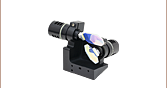
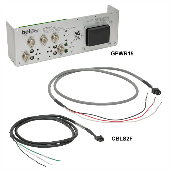
Zoom- GPWR15 Power Supply: ±15 V Power Supply for Single- and Dual-Axis Systems; One Supply Can Power up to Two Galvos
- QG, QS, SS, and SP Series VantagePro® Galvanometer Scanners
- BLINK Focusers
- XG Series Scan Heads
- GPWR15 Power Supply Specs
- Open Frame Requires Cables to be Soldered In
- Input: 100-120 or 220-240 VAC
- Output: ±15 V @ 5 A (150 W Max Power)
- Operating Temperature: 0 to 50 °C
- Dimensions: 14.0" x 4.9" x 3.5" (356 mm x 124 mm x 90 mm)
- CBLS2F: Command and Power Cables for QS7 and QS10 Series Galvanometer Scanners and BLINK High-Speed Focusers (One Set Required per Axis)
- CBLS3F: Command and Power Cables for QG4/5 and QS15/20/30/45 Series Galvanometer Scanners (One Set Required per Axis)
The GPWR15 Power Supply is a low noise, linear supply designed to minimize electrical interference for maximum system resolution. The compatible systems include the QG, QS, SS, and SP series Galvanometers Scanners, the BLINK Focusers, and the XG Series Scan Heads. This power supply delivers ±15 VDC at 5 A and is configured to accept a mains voltage of 100 - 120 or 220 - 240 VAC. It has an open frame, allowing the user to solder the compatible power cable into the system.
The CBLS2F Command and Power Cable Set can be used to connect the GPWR15 power supply to the QS7/10 series galvo scanners or the BLINK high speed focuser. The power cable has a four pin connector on one end for compatibility with the QS7/10 galvos and BLINK focusers and three bare wires for soldering to the GPWR15 power supply on the other end. The command cable has a two pin connector on one end for compatibility with the QS7/10 galvos and BLINK focusers and three bare wires for soldering to a user-supplied controller on the other end.
The CBLS3F Power and Command Cable set can be used to connect the GPWR15 power supply to the QG4/5, QS15/20/30/45, SS, or SP series galvo scanners. The power cable has a three pin connector on one end and three bare wires for soldering to the GPWR15 power supply on the other end. The command cable has a four pin connector on one end and three bare wires for soldering to a user-supplied controller on the other end.

 Zoom
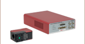
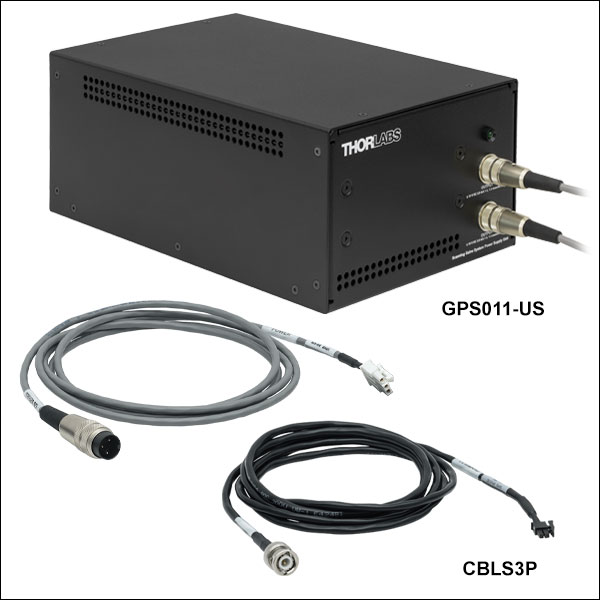
Zoom- GPS011 Series: ±15 V Power Supply for Single- and Dual-Axis Systems; One Supply Can Power up to Two Galvos
- QS7, QS10, QS15, and QS20 Series VantagePro® Galvanometer Scanners
- BLINK Focusers
- XG Series Scan Heads
- GPS011 Series Specs:
- Enlcosed Unit Allows Cables to Directly Connect to the System
- Switchable Input: 100 VAC / 50 or 60 Hz, 115 VAC / 60 Hz, 230 VAC / 50 Hz
- Output: ±15 VDC @ 3 A
- Operating Temperature: 5 to 40 °C
- Dimensions: 7.05" x 10.79" x 4.8" (179 mm x 274 mm (Max) x 122 mm)
- CBLS2P: Command and Power Cable Set for QS7/10 Series Scanning Galvanometer Systems and BLINK High-Speed Focusers
- CBLS3P: Command and Power Cable Set for QG4/5 and QS15/20 Series Scanning Galvanometer Systems
The GPS011 Series Power Supplies are low noise, linear supplies designed to minimize electrical interference for maximum system resolution for 1D and 2D galvanometer systems. The compatible systems include the QG4, QG5, QS7, QS10, QS15, and QS20 Series Galvanometers Scanners, the BLINK Focusers, and the XG Series Scan Heads. These power supplies deliver ±15 VDC at 3 A and are configured to accept a mains voltage of 115 VAC (Item # GPS011-US), 230 VAC (Item # GPS011-EC), or 100 VAC (Item # GPS011-JP). The GPS011 units are enclosed, allowing for direct connection with the compatible power cable without soldering.
Please note that the GPS011 series power supplies are insufficient for driving the QS30/45 Scanning Galvanometer Systems. Additionally, for the compatible galvos, Thorlabs recommends keeping the RMS current at 1 A or below.
The CBLS2P Power and Command Cable Set can be used to connect the GPS011 series galvo system linear power supplies to the QS7/10 series galvo scanners or the BLINK high speed focuser. The power cable has a three-pin circular connector on one end for compatibility with the GPS011 series and a four pin connector on the other end for compatibility with the BLINK focusers and QS7/10 galvos. The command cable has a BNC connector on one end for compatibility with a user-supplied controller and a two pin connector on the other end for compatibility with the BLINK focusers and QS7/10 galvos.
The CBLS3P Power and Command Cable set can be used to connect the GPS011 series galvo system linear power supplies to the QG4/5 and QS15/20 series galvo scanners. The power cable has a three-pin circular connector on one end for compatibility with the GPS011 series power supplies and a three pin connector on the other end for compatibility with the QG4/5 and QS15/20 galvos. The command cable has a BNC connector on one end for compatibility with a user-supplied controller and a four pin connector on the other end for compatibility with the QG4/5 and QS15/20 galvos.

 Zoom
Zoom
Click to Enlarge
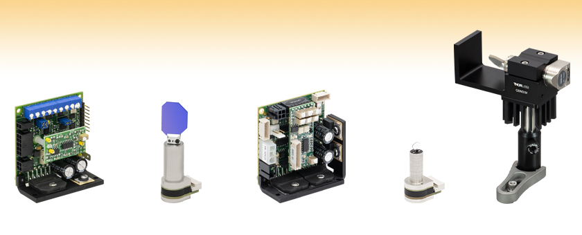
A QS20Y-AG galvo is post-mounted in the QSM2/M mount in a vertical orientation.

| QSMx Mount | Drawingsa | Compatible QSx Galvonometer |
|---|---|---|
| QSM1(/M) |  |
QS7 or QS10 |
| QSM2(/M) |  |
QS15 or QS20 |
| QSM3(/M) |  |
QS30 or QS45 |
| QSM4(/M) |  |
QG4 or QG5 |
- Mounts for Ø4 mm - Ø45 mm Beam Single Axis Galvanometers (Sold Separately Above)
- Two-Piece Clamp Mechanism Avoids Contact With Mirror Surfaces
- Vertical or Horizontal Mounting on Posts or Translation Stages
- Dowel Hole/Slot Design for Repeatable Precision Mounting on MT Translation Stages
- Compatible with GHS003(/M) Heat Sinks
Thorlabs' QSMx(/M) mounts provide a convenient solution for mounting the QS and QG single-axis galvo systems sold above. The holes available for mounting on our posts or translation stages in either verical or horizontal orientations are shown in the diagrams below. The galvo is secured using a two-piece clamp, allowing it to be installed without passing the sensitive mirror through the mount. For applications with highly variable drive signal waveforms that require additional heat dissipation, all mounts are compatible with the GHS003(/M) heat sinks. Refer to the table above to select the compatible mount for each single-axis galvanometer.
A plastic insulating shim (0.002" thick) is included with QSM3(/M) mounts to protect the capacitive position detector from electrical noise. It is recommended that users wrap the shim around the galvo prior to mounting for electrical isolation.