 Products Home / Optical Fiber & Fiber Patch Cables / Single Mode Fiber Optic Patch Cables / Thermally-Expanded-Core (TEC) Fiber Patch Cables
Thermally-Expanded-Core (TEC) Fiber Patch Cables
- SM Patch Cables with Thermally-Expanded Core (TEC) on One End
- Designed for Easier Coupling from Free Space
- 980 - 1250 nm or 1460 - 1620 nm Wavelength Range
- AR Coating on TEC End Reduces Coupling Loss
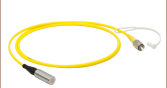
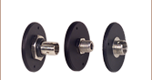
P1-1060TEC-2
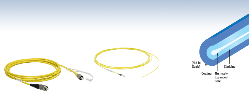
TEC Fiber Patch Cable with FC/PC Connectors
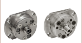
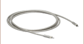
P6-1550TEC-2
TEC Fiber Patch Cable with Ø2.5 mm Ferrule and Scissor-Cut Ends
TEC Fiber Cores are Thermally Expanded via Heating to Ease Coupling from Free Space


Please Wait
| Item # Prefix |
TEC End (AR Coated) |
Uncoated End |
|---|---|---|
| P1 | FC/PC (Black Boot) | FC/PC |
| P5 | FC/PC (Black Boot) | FC/APC |
| P6 | Ø2.5 mm Ferrule with Slotted Flange | Scissor Cut |
| Coated Patch Cables Selection Guide |
|---|
| Single Mode AR-Coated Patch Cables |
| TEC Single Mode AR-Coated Patch Cables |
| Polarization-Maintaining AR-Coated Patch Cables |
| Multimode AR-Coated Patch Cables |
| HR-Coated Patch Cables |
| Beamsplitter-Coated Patch Cables |
| Stock Single Mode Patch Cables Selection Guide | |
|---|---|
| Standard Cables | FC/PC to FC/PC |
| FC/APC to FC/APC | |
| Hybrid | |
| AR-Coated Patch Cables | |
| Thermally-Expanded-Core (TEC) Patch Cables | |
| HR-Coated Patch Cables | |
| Beamsplitter-Coated Patch Cables | |
| MIR Fluoride Fiber Patch Cables | |

Features
- Thermally-Expanded Core Increases Mode Field Diameter (MFD) for Easier Coupling
- Easier to Couple from Free Space while Retaining Optical Properties of SM Fiber
- 980 - 1250 nm or 1420 - 1620 nm Operating Wavelength Range
- TEC End of Fiber is AR Coated for Reduced Coupling Loss
- Patch Cables Available from Stock with:
- 2.0 mm Narrow Key FC/PC (TEC) to FC/PC Connectors
- 2.0 mm Narrow Key FC/PC (TEC) to FC/APC Connectors
- Ø2.5 mm Ferrule with Slotted Flange (TEC) to Scissor Cut
- Contact Tech Support for Custom Configurations
Thorlabs' Thermally-Expanded-Core (TEC) Fiber Patch Cables are less sensitive to positional offsets than single mode fiber when coupling into a fiber from free space. Utilizing our Vytran® Fiber Processing Technology, these fibers are created by heating a conventional single mode fiber on one end to expand the core size over a ~2.5 mm length. In free-space coupling applications, this feature allows the treated end of the fiber to accept a beam with a larger mode field diameter while retaining the single mode and optical properties of the fiber (see the Coupling Performance tab for testing information). TEC fibers are often employed in building fiber-based optical isolators, tunable wavelength filters, and variable optical attenuators.
Multiple options for fiber patch cables with TEC ends are available from stock. Two wavelength ranges are available: 980 nm - 1250 nm and 1460 nm - 1620 nm. The TEC end of the fiber is AR coated with an average reflectance < 0.5% over the specified wavelength range to reduce losses when coupling from a free-space source. This end of the fiber has a shrink wrap label that lists key specifications. Connector options include 2.0 mm narrow key FC/PC or FC/APC connectors, a Ø2.5 mm ferrule, and a scissor cut bare fiber for splicing. The Ø2.5 mm ferrule to scissor cut patch cable is jacketed in a Ø900 µm tubing while the FC/PC and FC/APC patch cables use a Ø3 mm tubing (see the table to the upper right for available combinations).
Custom patch cables are also available. For more information, contact Tech Support.
There are several methods for cleaning an AR-coated connector end without damaging the coating. Gently spraying compressed air over the connector tip is ideal. Other methods include gently wiping using a lint-free optical cloth or FCC-7020 Fiber Connector Cleaner soaked with isopropanol or methanol. Dry wipes should not be used as this can damage the AR coating.

Click to Enlarge
Schematic of setup for measuring coupling performance.
Coupling Performance
TEC fibers, due to their expanded core diameter on one end, are less sensitive to positional offsets than standard single mode fiber when coupling into the fiber from free space. To provide a point of comparison, we measured the coupling loss of a free-space beam coupled into a TEC patch cable and standard patch cable while varing the offset on the x axis and z axis (as shown in the diagram to the right). A C151TMD-C aspheric lens was used to couple light into both standard and TEC fibers. A cable using 1060XP fiber and the P1-1060TEC-2 patch cable were tested at 980 nm and 1064 nm, while a cable using 1550BHP fiber and the P1-1550TEC-2 patch cable were tested at 1550 nm. Movement of the patch cable relative to the input beam was accomplished using a MBT616D 3-Axis Stage.
The graphs below detail the fiber coupling performance of the tested patch cables. In general, for the same x-axis or z-axis offset, the coupling loss is lower for the TEC fiber patch cable than the standard fiber. At 0 µm offset in either the x axis of z axis, the performance of the standard fiber and TEC patch cable are similar. In summary, these test results show that TEC fibers are much less sensitive to fiber position offsets than standard fibers while maintaining similar coupling loss at the optimal fiber position. Please note that these measurements are typical and that performance may vary from cable to cable due to manufacturing tolerances.

Click to Enlarge
Plot comparing coupling performance between 1060XP standard fiber and P1-1060TEC-2 thermally-expanded core fiber.

Click to Enlarge
Plot comparing coupling performance between 1060XP standard fiber and P1-1060TEC-2 thermally-expanded core fiber.

Click to Enlarge
Plot comparing coupling performance between 11550BHP standard fiber and P1-1550TEC-2 thermally-expanded core fiber.

Click to Enlarge
The left image shows the intensity profile of the beam propagated through the fiber overlaid on the fiber itself. The right image shows the standard intensity profile of the beam propagated through the fiber with the MFD and core diameter called out.
Definition of the Mode Field Diameter
The mode field diameter (MFD) is one measure of the beam width of light propagating in a single mode fiber. It is a function of wavelength, core radius, and the refractive indices of the core and cladding. While much of the light in an optical fiber is trapped within the fiber core, a small fraction propagates in the cladding. The light can be approximated as a Gaussian power distribution as shown to the right, where the MFD is the diameter at which the optical power is reduced to 1/e2 from its peak level.
Measurement of MFD
The measurement of MFD is accomplished by the Variable Aperture Method in the Far Field (VAMFF). An aperture is placed in the far field of the fiber output, and the intensity is measured. As successively smaller apertures are placed in the beam, the intensity levels are measured for each aperture; the data can then be plotted as power vs. the sine of the aperture half-angle (or the numerical aperture for an SM fiber).
The MFD is then determined using Petermann's second definition, which is a mathematical model that does not assume a specific shape of power distribution. The MFD in the near field can be determined from this far-field measurement using the Hankel Transform.
| Quick Links |
|---|
| Damage at the Air / Glass Interface |
| Intrinsic Damage Threshold |
| Preparation and Handling of Optical Fibers |
Laser-Induced Damage in Silica Optical Fibers
The following tutorial details damage mechanisms relevant to unterminated (bare) fiber, terminated optical fiber, and other fiber components from laser light sources. These mechanisms include damage that occurs at the air / glass interface (when free-space coupling or when using connectors) and in the optical fiber itself. A fiber component, such as a bare fiber, patch cable, or fused coupler, may have multiple potential avenues for damage (e.g., connectors, fiber end faces, and the device itself). The maximum power that a fiber can handle will always be limited by the lowest limit of any of these damage mechanisms.
While the damage threshold can be estimated using scaling relations and general rules, absolute damage thresholds in optical fibers are very application dependent and user specific. Users can use this guide to estimate a safe power level that minimizes the risk of damage. Following all appropriate preparation and handling guidelines, users should be able to operate a fiber component up to the specified maximum power level; if no maximum is specified for a component, users should abide by the "practical safe level" described below for safe operation of the component. Factors that can reduce power handling and cause damage to a fiber component include, but are not limited to, misalignment during fiber coupling, contamination of the fiber end face, or imperfections in the fiber itself. For further discussion about an optical fiber’s power handling abilities for a specific application, please contact Thorlabs’ Tech Support.
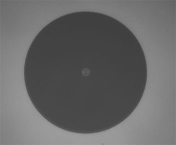
Click to Enlarge
Undamaged Fiber End
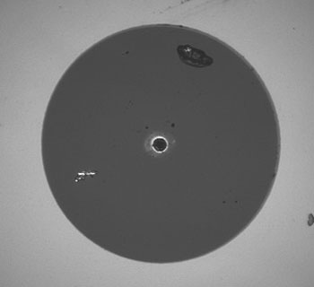
Click to Enlarge
Damaged Fiber End
Damage at the Air / Glass Interface
There are several potential damage mechanisms that can occur at the air / glass interface. Light is incident on this interface when free-space coupling or when two fibers are mated using optical connectors. High-intensity light can damage the end face leading to reduced power handling and permanent damage to the fiber. For fibers terminated with optical connectors where the connectors are fixed to the fiber ends using epoxy, the heat generated by high-intensity light can burn the epoxy and leave residues on the fiber facet directly in the beam path.
| Estimated Optical Power Densities on Air / Glass Interfacea | ||
|---|---|---|
| Type | Theoretical Damage Thresholdb | Practical Safe Levelc |
| CW (Average Power) |
~1 MW/cm2 | ~250 kW/cm2 |
| 10 ns Pulsed (Peak Power) |
~5 GW/cm2 | ~1 GW/cm2 |
Damage Mechanisms on the Bare Fiber End Face
Damage mechanisms on a fiber end face can be modeled similarly to bulk optics, and industry-standard damage thresholds for UV Fused Silica substrates can be applied to silica-based fiber. However, unlike bulk optics, the relevant surface areas and beam diameters involved at the air / glass interface of an optical fiber are very small, particularly for coupling into single mode (SM) fiber. therefore, for a given power density, the power incident on the fiber needs to be lower for a smaller beam diameter.
The table to the right lists two thresholds for optical power densities: a theoretical damage threshold and a "practical safe level". In general, the theoretical damage threshold represents the estimated maximum power density that can be incident on the fiber end face without risking damage with very good fiber end face and coupling conditions. The "practical safe level" power density represents minimal risk of fiber damage. Operating a fiber or component beyond the practical safe level is possible, but users must follow the appropriate handling instructions and verify performance at low powers prior to use.
Calculating the Effective Area for Single Mode Fibers
The effective area for single mode (SM) fiber is defined by the mode field diameter (MFD), which is the cross-sectional area through which light propagates in the fiber; this area includes the fiber core and also a portion of the cladding. To achieve good efficiency when coupling into a single mode fiber, the diameter of the input beam must match the MFD of the fiber.
As an example, SM400 single mode fiber has a mode field diameter (MFD) of ~Ø3 µm operating at 400 nm, while the MFD for SMF-28 Ultra single mode fiber operating at 1550 nm is Ø10.5 µm. The effective area for these fibers can be calculated as follows:
SM400 Fiber: Area = Pi x (MFD/2)2 = Pi x (1.5 µm)2 = 7.07 µm2 = 7.07 x 10⁻⁸ cm2
SMF-28 Ultra Fiber: Area = Pi x (MFD/2)2 = Pi x (5.25 µm)2 = 86.6 µm2 = 8.66 x 10⁻⁷ cm2
To estimate the power level that a fiber facet can handle, the power density is multiplied by the effective area. Please note that this calculation assumes a uniform intensity profile, but most laser beams exhibit a Gaussian-like shape within single mode fiber, resulting in a higher power density at the center of the beam compared to the edges. Therefore, these calculations will slightly overestimate the power corresponding to the damage threshold or the practical safe level. Using the estimated power densities assuming a CW light source, we can determine the corresponding power levels as:
SM400 Fiber: 7.07 x 10⁻⁸ cm2 x 1 MW/cm2 = 7.1 x 10⁻⁸ MW = 71 mW (Theoretical Damage Threshold)
7.07 x 10⁻⁸ cm2 x 250 kW/cm2 = 1.8 x 10⁻⁵ kW = 18 mW (Practical Safe Level)
SMF-28 Ultra Fiber: 8.66 x 10⁻⁷ cm2 x 1 MW/cm2 = 8.7 x 10⁻⁷ MW = 870 mW (Theoretical Damage Threshold)
8.66 x 10⁻⁷ cm2 x 250 kW/cm2 = 2.1 x 10⁻⁴ kW = 210 mW (Practical Safe Level)
Effective Area of Multimode Fibers
The effective area of a multimode (MM) fiber is defined by the core diameter, which is typically far larger than the MFD of an SM fiber. For optimal coupling, Thorlabs recommends focusing a beam to a spot roughly 70 - 80% of the core diameter. The larger effective area of MM fibers lowers the power density on the fiber end face, allowing higher optical powers (typically on the order of kilowatts) to be coupled into multimode fiber without damage.
Damage Mechanisms Related to Ferrule / Connector Termination
 Click to Enlarge
Plot showing approximate input power that can be incident on a single mode silica optical fiber with a termination. Each line shows the estimated power level due to a specific damage mechanism. The maximum power handling is limited by the lowest power level from all relevant damage mechanisms (indicated by a solid line).
Fibers terminated with optical connectors have additional power handling considerations. Fiber is typically terminated using epoxy to bond the fiber to a ceramic or steel ferrule. When light is coupled into the fiber through a connector, light that does not enter the core and propagate down the fiber is scattered into the outer layers of the fiber, into the ferrule, and the epoxy used to hold the fiber in the ferrule. If the light is intense enough, it can burn the epoxy, causing it to vaporize and deposit a residue on the face of the connector. This results in localized absorption sites on the fiber end face that reduce coupling efficiency and increase scattering, causing further damage.
For several reasons, epoxy-related damage is dependent on the wavelength. In general, light scatters more strongly at short wavelengths than at longer wavelengths. Misalignment when coupling is also more likely due to the small MFD of short-wavelength SM fiber that also produces more scattered light.
To minimize the risk of burning the epoxy, fiber connectors can be constructed to have an epoxy-free air gap between the optical fiber and ferrule near the fiber end face. Our high-power multimode fiber patch cables use connectors with this design feature.
Determining Power Handling with Multiple Damage Mechanisms
When fiber cables or components have multiple avenues for damage (e.g., fiber patch cables), the maximum power handling is always limited by the lowest damage threshold that is relevant to the fiber component. In general, this represents the highest input power that can be incident on the patch cable end face and not the coupled output power.
As an illustrative example, the graph to the right shows an estimate of the power handling limitations of a single mode fiber patch cable due to damage to the fiber end face and damage via an optical connector. The total input power handling of a terminated fiber at a given wavelength is limited by the lower of the two limitations at any given wavelength (indicated by the solid lines). A single mode fiber operating at around 488 nm is primarily limited by damage to the fiber end face (blue solid line), but fibers operating at 1550 nm are limited by damage to the optical connector (red solid line).
In the case of a multimode fiber, the effective mode area is defined by the core diameter, which is larger than the effective mode area for SM fiber. This results in a lower power density on the fiber end face and allows higher optical powers (on the order of kilowatts) to be coupled into the fiber without damage (not shown in graph). However, the damage limit of the ferrule / connector termination remains unchanged and as a result, the maximum power handling for a multimode fiber is limited by the ferrule and connector termination.
Please note that these are rough estimates of power levels where damage is very unlikely with proper handling and alignment procedures. It is worth noting that optical fibers are frequently used at power levels above those described here. However, these applications typically require expert users and testing at lower powers first to minimize risk of damage. Even still, optical fiber components should be considered a consumable lab supply if used at high power levels.
Intrinsic Damage Threshold
In addition to damage mechanisms at the air / glass interface, optical fibers also display power handling limitations due to damage mechanisms within the optical fiber itself. These limitations will affect all fiber components as they are intrinsic to the fiber itself. Two categories of damage within the fiber are damage from bend losses and damage from photodarkening.
Bend Losses
Bend losses occur when a fiber is bent to a point where light traveling in the core is incident on the core/cladding interface at an angle higher than the critical angle, making total internal reflection impossible. Under these circumstances, light escapes the fiber, often in a localized area. The light escaping the fiber typically has a high power density, which burns the fiber coating as well as any surrounding furcation tubing.
A special category of optical fiber, called double-clad fiber, can reduce the risk of bend-loss damage by allowing the fiber’s cladding (2nd layer) to also function as a waveguide in addition to the core. By making the critical angle of the cladding/coating interface higher than the critical angle of the core/clad interface, light that escapes the core is loosely confined within the cladding. It will then leak out over a distance of centimeters or meters instead of at one localized spot within the fiber, minimizing the risk of damage. Thorlabs manufactures and sells 0.22 NA double-clad multimode fiber, which boasts very high, megawatt range power handling.
Photodarkening
A second damage mechanism, called photodarkening or solarization, can occur in fibers used with ultraviolet or short-wavelength visible light, particularly those with germanium-doped cores. Fibers used at these wavelengths will experience increased attenuation over time. The mechanism that causes photodarkening is largely unknown, but several fiber designs have been developed to mitigate it. For example, fibers with a very low hydroxyl ion (OH) content have been found to resist photodarkening and using other dopants, such as fluorine, can also reduce photodarkening.
Even with the above strategies in place, all fibers eventually experience photodarkening when used with UV or short-wavelength light, and thus, fibers used at these wavelengths should be considered consumables.
Preparation and Handling of Optical Fibers
General Cleaning and Operation Guidelines
These general cleaning and operation guidelines are recommended for all fiber optic products. Users should still follow specific guidelines for an individual product as outlined in the support documentation or manual. Damage threshold calculations only apply when all appropriate cleaning and handling procedures are followed.
-
All light sources should be turned off prior to installing or integrating optical fibers (terminated or bare). This ensures that focused beams of light are not incident on fragile parts of the connector or fiber, which can possibly cause damage.
-
The power-handling capability of an optical fiber is directly linked to the quality of the fiber/connector end face. Always inspect the fiber end prior to connecting the fiber to an optical system. The fiber end face should be clean and clear of dirt and other contaminants that can cause scattering of coupled light. Bare fiber should be cleaved prior to use and users should inspect the fiber end to ensure a good quality cleave is achieved.
-
If an optical fiber is to be spliced into the optical system, users should first verify that the splice is of good quality at a low optical power prior to high-power use. Poor splice quality may increase light scattering at the splice interface, which can be a source of fiber damage.
-
Users should use low power when aligning the system and optimizing coupling; this minimizes exposure of other parts of the fiber (other than the core) to light. Damage from scattered light can occur if a high power beam is focused on the cladding, coating, or connector.
Tips for Using Fiber at Higher Optical Power
Optical fibers and fiber components should generally be operated within safe power level limits, but under ideal conditions (very good optical alignment and very clean optical end faces), the power handling of a fiber component may be increased. Users must verify the performance and stability of a fiber component within their system prior to increasing input or output power and follow all necessary safety and operation instructions. The tips below are useful suggestions when considering increasing optical power in an optical fiber or component.
-
Splicing a fiber component into a system using a fiber splicer can increase power handling as it minimizes possibility of air/fiber interface damage. Users should follow all appropriate guidelines to prepare and make a high-quality fiber splice. Poor splices can lead to scattering or regions of highly localized heat at the splice interface that can damage the fiber.
-
After connecting the fiber or component, the system should be tested and aligned using a light source at low power. The system power can be ramped up slowly to the desired output power while periodically verifying all components are properly aligned and that coupling efficiency is not changing with respect to optical launch power.
-
Bend losses that result from sharply bending a fiber can cause light to leak from the fiber in the stressed area. When operating at high power, the localized heating that can occur when a large amount of light escapes a small localized area (the stressed region) can damage the fiber. Avoid disturbing or accidently bending fibers during operation to minimize bend losses.
-
Users should always choose the appropriate optical fiber for a given application. For example, large-mode-area fibers are a good alternative to standard single mode fibers in high-power applications as they provide good beam quality with a larger MFD, decreasing the power density on the air/fiber interface.
-
Step-index silica single mode fibers are normally not used for ultraviolet light or high-peak-power pulsed applications due to the high spatial power densities associated with these applications.
| Posted Comments: | |
Samuele Grandi
(posted 2023-08-21 16:00:36.73) Would it be possible to have a custom option for light in the visible? Around 600nm jdelia
(posted 2023-08-22 01:41:44.0) Thank you for contacting Thorlabs. You can request customized items by emailing your local tech support team. I have contacted you directly to discuss the feasibility of this request. Suk Hyun Kim
(posted 2023-03-06 11:46:19.403) I would like ask questions on damage thresold.
I want to use this product P1-1550TEC-2 for laser coupling into the fiber.
The warning sign says,
"Additionally, because of the AR coating, TEC fiber patch cables should not be used for high-power applications."
Here is my question. What is the criteria of high-power?
the Mode Field Diameter of the product P1-1550TEC-2 is 20um at the TEC side, giving cross section around 314 um2.
The Theoretical Damage Threshold is 3.14 Watt. This is the range I want to use. It it OK to use laser beam with power 1~2 Watt, or is it prevented for AR coating? jgreschler
(posted 2023-03-13 08:18:38.0) Thank you for reaching out to Thorlabs. The 1-2W range for these patch cables is considered high power, it would not be suitable for applications at those power ranges. I have reached out to you directly to discuss possible alternatives which will work for your power range. S. M.
(posted 2022-11-02 15:54:19.34) What is the return loss of the TEC AR end facette as compared to an APC connector end facette? user
(posted 2022-03-21 12:18:50.61) Hello. I am interested in coupling light (532 nm) from a reflective collimator in to a single mode fiber. Once I achieve a good coupling efficiency, I would like to start working with broad band light of range 450 nm to 650 nm. But I am unable to achieve high coupling efficiency with 532 nm due to small mode field diameter of the fiber. I think these TEC fibers are promising. Do you think these fibers suits for my application and can be produced for 450 nm to 650 nm?. Thanks. jgreschler
(posted 2022-03-22 11:13:29.0) Thank you for reaching out to Thorlabs. In general, yes, the thermally expanded cores facilitate easier coupling, though many issues with single mode coupling can also be addressed with the method of coupling. I have reached out to you directly to discuss methods of improving coupling efficiency. user
(posted 2020-07-25 12:30:40.797) In a previous answer to a question in this section, you said that the measurements in the "Coupling Performance" section were made using the same C151TMD-C lens for both standard SMF and TEC fiber. However, according to your "Choosing a Lens for Fiber Coupling" guide, you need to choose your focal length depending on the MTF of the fiber, so you cannot use the same lens to compare the coupling performance. I am interested in comparing the coupling performance when using the correct lens for each fiber. nbayconich
(posted 2020-07-27 01:51:22.0) Thank you for contacting Thorlabs. Fiber coupling performance will depend on several factors such as the source wavelength, beam diameter and the selected lens’ focal length which determine the size of your focused spot. Ideally you will want to select a lens which will yield a focused spot similar in size to the fiber’s MFD to guarantee high coupling efficiency. The TEC end of these types of fiber cables initially has a much larger MFD than a standard fiber so it allows the user some error in their alignment hence the lower coupling loss vs. axis offset seen in the TEC fibers compared to the standard fibers. You can use the same lens for both the TEC P1-1060TEC-2 and a standard 1060XP fiber cable, to guarantee a high coupling efficiency make sure to select a lens which produces a focused spot similar in size to the “standard” MFD size of the selected fiber cable. Alberto Carrasco
(posted 2019-08-28 14:34:29.83) Do you have or can you make these fibers with polarization-maintaining behavior? YLohia
(posted 2019-08-28 10:20:16.0) Hello Alberto, thank you for contacting Thorlabs. I will reach out to you directly to discuss the possibility of offering this customization. Alberto Carrasco
(posted 2019-08-28 14:29:27.85) Can you say what specific lens you used in the coupling performance measurements? It' a very important parameter to understand those measurements. Thank you. YLohia
(posted 2019-08-28 10:40:34.0) Hello, a C151TMD-C aspheric lens was used to couple light into both standard and TEC fibers (see "Coupling Performance" tab for more information). jeroen.missinne
(posted 2018-03-14 16:27:38.077) Hello,
I would be interested in a SMF-28 with a TEC on 1 end. However, I would need a MFD of 50um at the TEC side. Is it possible to provide this and if yes, at which price?
The TEC end may be a ferrule, ideally AR coated for operation around 1550nm. The SMF-28 should have a FC/APC connector.
Thanks for the info. YLohia
(posted 2018-03-30 11:46:32.0) Hello, thank you for contacting Thorlabs. We will reach out to you directly to discuss the possibility of doing this. |
| Item # | Fiber Type | Operating Wavelength | Mode Field Diametera | AR Coatingb | Max Attenuationc | NAd | Cladding/Coating Diameter | Connectors | Jacket | ||
|---|---|---|---|---|---|---|---|---|---|---|---|
| TEC | Standard | TEC | Standard | ||||||||
| P1-1060TEC-2 | 1060XP | 980 - 1250 nm | 12.4 ± 1.0 µm | 6.2 ± 0.5 µm | 850 - 1250 nm Ravg < 0.5% |
≤2.1 dB/km @ 980 nm ≤1.5 dB/km @ 1060 nm |
0.07 | 0.14 | 125 ± 0.5 µm / 245 ± 10 µm |
FC/PC (TEC) to FC/PC | Ø3 mm FT030-Y |
| P5-1060TEC-2 | FC/PC (TEC) to FC/APC | ||||||||||
| P6-1060TEC-2 | Ø2.5 mm Ferrule (TEC) to Scissor Cut | Ø900 µm | |||||||||
| Item # | Fiber Type | Operating Wavelength | Mode Field Diametera | AR Coatingb | Max Attenuationc |
NAd | Cladding/Coating Diameter | Connectors | Jacket | ||
|---|---|---|---|---|---|---|---|---|---|---|---|
| TEC | Standard | TEC | Standard | ||||||||
| P1-1550TEC-2 | 1550BHP | 1460 - 1620 nm | 19.0 ± 1.0 µm | 9.5 ± 0.5 µm | 1050 - 1620 nm Ravg < 0.5% |
0.5 dB/km @ 1550 nm | 0.06 | 0.13 | 125 ± 1.0 µm / 245 ± 15 µm |
FC/PC (TEC) to FC/PC | Ø3 mm FT030-Y |
| P5-1550TEC-2 | FC/PC (TEC) to FC/APC | ||||||||||
| P6-1550TEC-2 | Ø2.5 mm Ferrule (TEC) to Scissor Cut | Ø900 µm | |||||||||