Two-Axis VantagePro® Galvanometer System Scan Heads
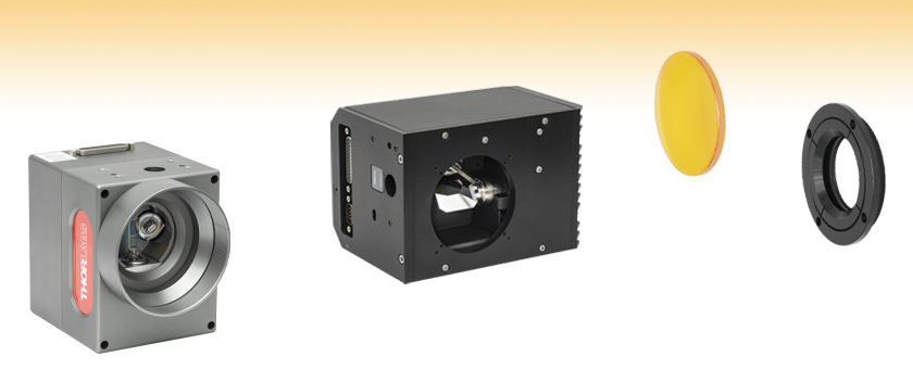
- Packaged XY Galvanometer Systems
- Options for 10 mm, 15 mm, and 20 mm Beam Diameters
- Configured for Digital Commands
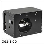
XG215-CD
Galvanometer Scan Head, CO2 Laser Mirrors
DCB210-AG
Galvanometer Scan Head
with Digital Processing,
Silver Mirrors
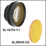
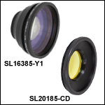
Scan Lens and Lens Ring
for XG Series Scan Heads
SL10048-CD
LR150848

Please Wait
Large-Volume Orders
For orders where a large quantity of an item is purchased and the delivery of that item is scheduled with our production (i.e., not taken directly from inventory), Thorlabs passes on to the customer the cost savings associated with planned production of high volumes of that item. Since the volume and planned production are key to realizing the cost savings, we ask that you contact us to obtain volume pricing.
Additional requests can include custom optic sizes and coatings, specialized tuning, and variable cable options.
Applications
- Laser Marking
- Solar Scribing
- Welding with Metal or Plastic
- Micromachining
- Laser Cutting, Trimming, and Patterning
- Surface Treatment
- Ablation
- Engraving and Scribing
- Rapid Prototyping
- Additive Manufacturing
- Laser Surface Treatment
- Photovoltaic Production
Demo Units Available
Interested in trying a Two-Axis Scanning Galvo System Scan Head for your application? Contact us at techsales@thorlabs.com to request a demo unit.Features
- Packaged Two-Axis Galvanometer Scan Heads
- ±22.5° Optical Scan Angle
- XG Series for High-Speed Scanning Performance
- DCB Series with Advanced Digital Processor Control
- Protected Silver, Nd:YAG, or CO2 Mirrors Available
- Operate via XY2-100 Digital Signal Input
- Compact Housing
- Power Supply and Power Cable Available Separately
These Two-Axis VantagePro® Galvanometer Scan Heads provide two-dimensional scanning in a variety of laser applications. Each scan head consists of a dual-axis galvo motor and mirror assembly, two servo amplifiers, and communication electronics. The moving-magnet galvanometers deliver high speed and accuracy while integrated optical position detectors ensure precise control, high linearity, and low drift. The scan head housings are compact and include industry-standard mechanical interfaces for integration into a system.
The DCB Series Scan Heads are designed for OEM integration or easy plug-and-play operation. The system includes advanced digital signal processing (DSP) to rapidly compute and predict the exact drive impulses required to achieve small mirror movements with the fastest possible acceleration. The unit features self-tuning technology that automatically compensates for mechanical wear, extending its lifetime and eliminating issues associated with traditional analog servo filters. A detailed self-diagnosis and system check determine the operating parameters of the individual galvanometers, ensuring high accuracy and precise, error-free laser marking positioning.
Compatible power supplies and command cables are sold separately below. For the XG Series Scan Heads, there is a choice between an open frame or enclosed ±15 V power supply. For the DCB Series Scan Heads, a ±24 V open frame power supply is available. For a list of which power supplies and cables to use with which galvos, see the Galvo Compatibility tab.
System Control
These scan heads are configured to accept inputs via the XY2-100 communication protocol. This industry-standard digital interface integrates with PC-based hardware and software packages for laser marking and micromachining. We recommend the SAMLight software package from SCAPS; click here for information on this software. Analog input versions are also available.
Scan Lenses and Lens Ring Kits
A scan lens and lens ring are required in order to use a scan head. The XG series scan heads require both a scan lens and lens ring kit to be purchased separately; DCB series scan heads include a lens ring kit but require a scan lens separately. See the Scan Lenses and Rings tab to choose an appropriate scan lens and lens ring for your galvanometer scan head.
| Item # | XG210-AG | XG210-Y1 | XG210-Y1HP | XG215-CD | XG220-Y1 |
|---|---|---|---|---|---|
| Mirror | |||||
| Maximum Beam Diameter | 10 mm | 15 mm | 20 mm | ||
| Input/Output Beam Offseta | 13.6 mm | 19.6 mm | |||
| Coating Type | Protected Silver | Nd:YAG | Nd:YAG, High Power |
CO2 | Nd:YAG |
| Absolute Reflectance | 450 - 750 nm: 90 - 95% 750 nm - 10.6 µm: 95 - 98% | 99.5% at 1064 nm | 99.5% at 10.6 µm | 99.5% at 1064 nm | |
| Max Power | CW: 50 W/cm2 | CW: 500 W/cm2 | Pulsed: 10 J/cm2 (20 ns Pulse) |
CW: 500 W/cm2 | |
| Surface Quality | 40-20 Scratch-Dig | ||||
| Motor and Position Sensor | |||||
| Small Angle Step Responseb | 350 µs | 600 µs | 650 µs | ||
| Scale Drift | <100 ppm/°C | <70 ppm/°C | |||
| Zero Drift | 15 µrad/°C | ||||
| Linearity (50% Full Travel) | 99.90% | ||||
| Repeatability | 20 µrad | ||||
| Resolution (Mechanical) | 16 µrad | ||||
| Peak Current | ±3 A | ||||
| Maximum Scan Angle (Optical Angle) |
±22.5° | ||||
| Operating Temperature Range | 0 to 40 °C | ||||
| GPWR15 Power Supply Unit Specs | |
|---|---|
| Input | 100 - 120 VAC or 220 - 240 VAC |
| Output | ±15 V at 5 A (150 W Max Power) |
| Operating Temperature | 0 to 50 °C |
| Dimensions | 14.0" x 4.9" x 3.5" (356 mm x 124 mm x 90 mm) |
| GPS011 Series Linear Power Supply Unit Specs | |
|---|---|
| Switchable Input | 100V AC 50 or 60 Hz 115V AC 60 Hz 230 V AC 50 Hz |
| Output | ±15 V DC 3.0A/0.1A, 1.4/6.3 msec (maximum duty cycle)a |
| Operating Temperature | 5 to 40 °C |
| Dimensions | 179 mm x 274 mm (max) x 122 mm (7.05" x 10.79" x 4.8") |
| Item # | DCB210-AG | DCB210-Y1 | DCB210-Y1HP | DCB210-CD |
|---|---|---|---|---|
| Mirror | ||||
| Maximum Beam Diameter | 10 mm | |||
| Input/Output Beam Offseta | 12.5 mm | |||
| Coating Type | Protected Silver | Nd:YAG | Nd:YAG, High Power |
CO2 |
| Absolute Reflectance | 450 - 750 nm: 90 - 95% 750 nm - 10.6 µm: 95 - 98% |
99.5% at 1064 nm | 99.5% at 10.6 µm | |
| Max Power | CW: 50 W/cm2 | CW: 500 W/cm2 | Pulsed: 10 J/cm2 (20 ns Pulse) |
CW: 500 W/cm2 |
| Surface Quality | 40-20 Scratch-Dig | |||
| Motor and Position Sensor | ||||
| Small Angle Step Responseb | 0.28 ms | |||
| Scale Drift | <50 ppm/°C | |||
| Zero Drift | <20 µrad/°C | |||
| Linearity (50% Full Travel) | 99.50% | |||
| Resolution (Mechanical) | 10 µrad | |||
| Maximum Scan Angle (Optical Angle) |
±22.5° | |||
| Power Supply | ±24 V, 4 A | |||
| Operating Temperature | 0 to 40 °C | |||
| GPWR24 Power Supply Unit Specs | |
|---|---|
| Input | 100 - 120 VAC or 220 - 240 VAC |
| Output | ±24 V at 2.4 A (115 W Max Power) |
| Operating Temperature | 0 to 50 °C |
| Dimensions | 9.38" x 4.87" x 3.28" (238.3 mm x 123.7 mm x 83.3 mm) |
- Choose a Scan Lens based on desired specs on the left side of the table.
- Find the compatible Scan Head on the right side of the table.
- For XG series scan heads, find the compatible Lens Ring on the right side of the table.
- For DCB series scan heads, the lens ring is included with the scan head.
Scan Lens and Lens Ring Selection Guide
Use the table below to select a scan lens and lens ring for your galvanometer scan head. Scan lens item #s are listed in the green highlighted column, while galvanometer scan head item # prefixes are listed in the right half of the header row; lens ring item #s are given at the intersection of the compatible scan head and scan lens.
| Scan Lens | Scan Head (Item # Prefix XG) and Lens Ring (Item # Prefix LR) | |||||||
|---|---|---|---|---|---|---|---|---|
| Wavelength | Effective Focal Length |
Field Size | Working Distance | Item # | XG210 | XG215 | XG220 | DCB210 |
| 1064 nm | 100 mm | 69 x 69 mm² | 138 mm | SL10085-Y1 | LR102785 | - | - | - |
| 163 mm | Ø162.3 mm | 186 mm | SL16376-Y1 | LR152476 | - | - | - | |
| 163 mm | 113 x 113 mm² | 187.5 mm | SL16385-Y1 | - | - | - | Includeda | |
| 254 mm | Ø222.0 mm | 299 mm | SL25485X-Y1 | LR102385 | - | - | - | |
| 254 mm | 175 x 175 mm² | 281 mm | SL25485D-Y1 | - | - | - | Includeda | |
| 330 mm | Ø306.6 mm | 388 mm | SL33085-Y1 | LR102385 | - | LR201185 | - | |
| 420 mm | Ø411.0 mm | 494 mm | SL42085X-Y1 | LR102385 | - | LR201185 | - | |
| 420 mm | 290 x 290 mm² | 486 mm | SL42085D-Y1 | - | - | - | Includeda | |
| 10.6 µm | 100 mm | 70 x 70 mm² | 106.1 mm | SL10048-CD | - | LR150848 | - | - |
| 150 mm | 105 x 105 mm² | 166 mm | SL15085-CD | - | - | - | Includeda | |
| 175 mm | 120 x 120 mm² | 178.4 mm | SL17548-CD | - | LR150848 | - | - | |
| 200 mm | 140 x 140 mm² | 208.8 mm | SL20048-CD | - | LR150848 | - | - | |
| 201 mm | 140 x 140 mm² | 223 mm | SL20185-CD | - | - | - | Includeda | |
| 250 mm | 175 x 175 mm² | 266 mm | SL25085-CD | - | - | - | Includeda | |
| 300 mm | 210 x 210 mm² | 307.7 mm | SL30048-CD | - | LR150848 | - | - | |
Key Features of SurfBoard and
Pipeline Controllers
- Standard XY2-100 Communication
- Encoder Input for Mark-on-the-Fly
- Multi-Axis Mark-on-the-Fly
- Outputs for CW and Pulsed Lasers
- First Pulse Killer Output
- 16-Bit Position Resolution
- Analog and Digital Laser Power Control
- Multiple Scan Head Operation from a Single Controller
- Dedicated Step and Direction Outputs for 3-Axis Stepper Motor Control with Home Input
- Remote-Controlled or Stand-Alone Operation
- Dual Processor
- 1 GB Flash Memory
- 64 MB RAM
- 10/100 Ethernet
- 2-Channel XY2-100 3-Axis Digital Interface
- Six Inputs / Six Outputs, Optically-Isolated, 5 - 24 V Level
- Two 10-Bit Analog Inputs
- Two Analog Outputs (2, 5, 10 V Range)
- Ten Inputs / Ten Outputs Non-Isolated Digital TTL
- RS-232 Interface
Additional Key Features of
Pipeline Controller
- Laser Enable Key Switch with 5 Second Signal Delay
- Connector Ports for Simplified Wiring
- Controller-to-Laser Cable Options for Select Lasers
Thorlabs offers the SurfBoard and Pipeline galvo controllers for generating XY2-100 signals and system control of devices such as XY tables and rotary stages. Axes of motion may be controlled via I/O or RS-232. The hardware I/O can be configured to interact with other devices for handshaking and synchronizing functions. For assistance with ordering and configuring your galvo scanning hardware and software solution, please contact us.
SurfBoard Controller
The SurfBoard is a small form-factor, DIN rail mountable control card for the user that is looking for an increased level of flexibility in their integration. It is available with an enclosure for easy mounting or as a bare board for greater end-user customization.
Pipeline Controller
The Pipeline hardware is a 1U rack-mountable 19" controller and contains connector ports and safety features that allow for greater simplification of the wiring process. A front panel key switch with a 5-second delay, mark in progress indicator, and safety interlock loop are provided. The interface board implements key features necessary to manage fiber laser control signals.
Remote Control Software
Vectors and commands are uploaded from a host system over a USB or Ethernet connection. Execution is independent of the host computer, allowing for true real-time control. Jobs may be constructed and run from the WaveRunner GUI (click here to download) or by other user software through the Scan Card Interface option.
Standalone Operation
The Standalone/Flash option allows run-time operation without a PC. Up to 256 jobs may be stored and selected by either hardware or software methods. Ethernet connections allows remote access from any location for changing settings and job files. Combining Standalone/Flash with a WaveRunner dongle enables flexible embedded solutions for up to 16 laser-scanning stations. Only one WaveRunner software license is needed for job creation and editing where Standalone/Flash is implemented, providing significant cost savings for multiple workstation installations.
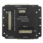
Click for Details
SurfBoard Galvo Controller
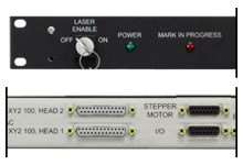
Click for Details
Pipeline Galvo Controller
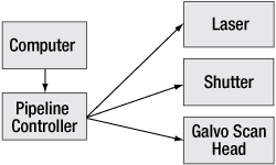
Typical Galvo Scanning System with
Pipeline Controller
Features
- Accommodates TrueType Fonts, Serialization, Radial Text, and Vertical Text
- Graphics Import Filters for Wide Variety of Formats:
- AI, SVG, BMP, DXF, HPGL, JPG, JOB, MCL, PCX, PLT, and WMF
- Real-Time Calculation of Laser and Scanner Signals
- Online Grid Correction
- Control Signals for Every Type of Laser
- Stand-Alone Operation or Integration with Host Computers or PLCs
- Capable of Operating Motion Control Devices (e.g.: XY Tables or Rotary Indexers)
Optional Software Modules
- Mark-on-the-Fly
- 3-Axis Scanning – Enables Z-Axis Adjustments
- Client Interface – Allows for Remote Control from Other Software, Such as ActiveX
- MultiHead – Enables Simultaneous Marking on up to 4 Heads
- Optic 3D – Wrap Objects Around 3D Surfaces, Allows for DXF File Import
- 3D/Rapid Prototype – Enables Slicing of Solids into Layers (Requires Client Interface)
- Flash – Standalone Capability
WaveRunner Scan Control Software
This advanced, fully-featured laser scanning software package is designed for use with our SurfBoard and Pipeline galvo system controllers (please see the Controller Options tab for more details). It enables the creation and editing of job files for laser marking, micromachining, and processing. Use the WaveRunner GUI to assemble text, images, bar codes, and serial numbers into job files, assign laser scanning parameters, and build automation scripts within a single interface. Graphic objects can be drawn natively or imported with support for a wide variety of formats. Markable objects can be organized into sequences which include control objects such as timers, I/Os, and motion control automation. Each object can be assigned unique laser processing parameters.
The WaveRunner Scan Control software can be configured to work with all laser types. A library of correction files is included for popular scanning lenses and custom lens correction files can be easily created. WaveRunner can also be used with our SurfBoard or Pipeline scan controllers to operate 2- or 3-axis scan systems, which are then capable of stand-alone operation or integration with host computers or programmable logic controllers (PLCs).
The table below illustrates how to assemble a galvo system. After picking the galvo needed, choose the applicable power supply and cable to match. A controller will also be needed for this system. Please refer to the Controller Options tab for more information.
| Galvo Compatability | |||
|---|---|---|---|
| Scan Heads | Compatible Power Supply (Supports up to Two Axes) |
Compatible Power Supply Cables (Choose One Per Axis) |
Compatible Command Cables (Choose One Per Axis) |
| XG Series | GPWR15 Open Frame Power Supplya | CBLPA16F | CBLA16D |
| GPS011 Series Enclosed Power Supplyb | CBLA6P | CBLA16D | |
| DCB Series | GPWR24 Open Frame Power Supplya | CBLA16F | |
| Posted Comments: | |
user
(posted 2024-04-17 07:40:27.913) Is there a specification for the maximum speed/acceleration of the "DCB210-CD" scanhead? ksosnowski
(posted 2024-05-10 10:39:37.0) Thanks for reaching out to Thorlabs. It is difficult to directly define the speed of the DCB210 scan heads as the galvo max speed depends strongly on the scan angle used, as well as the waveform/shape of the scan path. For small angles on the DCB210 series, we directly specify a 0.28ms small step response time for the galvo to settle at a position. I have reached out directly to discuss your application in further detail. Christiaan Van den Berg
(posted 2022-12-01 07:50:44.91) I would like to now the distance from the front of the housing to the mirror at the central ray for XG210 cdolbashian
(posted 2022-12-02 03:50:27.0) Thank you for reaching out to us with this inquiry. I have contacted you directly to discuss your application which would require such information! George Herring
(posted 2022-02-12 11:39:56.51) I'm looking at the possibility of integrating these scanners into a larger experimental system and I need a reliable way of controlling them which is compatible with my other software/electronic controls. Is there a simple control board available and/or can you provide full specifications on the communication protocol (XY2-100 is documented somewhat inconsistently online)? jgreschler
(posted 2022-02-24 11:34:24.0) Thank you for reaching out to Thorlabs. We do carry a line of modular galvo scanners that can be quoted on request. For more information please reach out to techsupport@thorlabs.com. We have contacted you directly to discuss this application further. J R
(posted 2021-07-27 05:47:36.327) I ordered XG210 with GPWR15 power supply. "Specifications and application data" of GPWR15 is the only technical document I received and it is lacking of the following information:
1) Should earth ground be connected to the housing of the power supply? Should the housing be afterwards connected to somewhere else?
2) Where exactly I have to connect +15 V, -15 V and GND cables of the power cable of the XG scanner head? Probably to the pins +OUT, -OUT and COM?
3) Probably -OUT pin must be directly connected to the -S, and +OUT to the +S?
4) Do I need to integrate an electrical fuse? cdolbashian
(posted 2021-08-27 10:09:00.0) Thank you for contacting us here at Thorlabs with your inquiries. Regarding your inquiries, I have reached out to you directly to complete the setup and troubleshooting of your galvo system. Chau Tran
(posted 2021-03-19 12:47:29.103) Hello,
We bought a galvo scan head (
DCB210-Y1HP) and some accessories from Thorlabs but we can not find a suitable angle bracket to connect the galvo scan head to other optomechanical parts.
The 4xM5 design on the scan head is not popular. Why aren't they M4 or M6? Their distances are also not familiar with Thorlabs' design (54x15 mm).
Another thing is no support documents such as drawings, 3d files for the lens SL16385-Y1 and it group. YLohia
(posted 2021-03-19 03:13:55.0) Hello, thank you for contacting Thorlabs. We will reach out to you directly to discuss this. Kent Ramthun
(posted 2021-02-27 13:11:16.66) Need a wiring diagram for the DB-25 connectorn the galvo head. We are providing our own controller to drive the galvo, but we do not know how to wire to this connector.!! YLohia
(posted 2021-03-08 08:26:18.0) Thank you for contacting Thorlabs. We have reached out to you directly with the connector wiring diagram. |

|
Included
|
Must Be Purchased Separately |
|
Optional Accessories |
|
- Ø10 mm, Ø15 mm, or Ø20 mm Max Beam Diameter
- Configured to Accept XY2-100 Digital Input Signals
These packaged 2-axis VantagePro® scan heads consist of XY galvanometer mirrors and drive electronics enclosed in an aluminum housing. Scan heads that accept beam diameters up to 10 mm, 15 mm, and 20 mm are available. Each scan head can be operated using an input via the XY2-100 communication protocol.
A scan lens and lens ring must be purchased separately to use these scan heads. See the Scan Lenses and Rings tab above for assistance in choosing these components.
The compatible power supply and cable set combinations are sold separately. Either choose the GPWR15 Power Supply with the CBLPA16F Power Cable and CBLA16D Galvanometer Command Cable or a GPS011 Series Power Supply with the CBLA16D Galvanometer Command Cable and CBLA6P Power Cable. The GPWR15 Power Supply has an open frame, allowing users to solder the compatible cables into the system, while a GPS011 Series Power Supply allows the user to directly connect the compatible cable without soldering.
| Key Specificationsa | |||||
|---|---|---|---|---|---|
| Item # | XG210-AG | XG210-Y1 | XG210-Y1HP | XG215-CD | XG220-Y1 |
| Max Beam Diameter | Ø10 mm | Ø15 mm | Ø20 mm | ||
| Coating | Protected Silver | Nd:YAG | Nd:YAG, High Power | CO2 | Nd:YAG |
| Wavelength Range | 450 nm - 10.6 µm | 1064 nm | 1064 nm | 10.6 µm | 1064 nm |
| Maximum Power | CW: 50 W/cm2 | CW: 500 W/cm2 | Pulsed: 10 J/cm2 (20 ns Pulse) |
CW: 500 W/cm2 | |
| Repeatability | 20 µrad | ||||
| Resolution | 16 µrad | ||||
| Maximum Scan Angle (Optical) | ±22.5° | ||||

|
Included
|
Must Be Purchased Separately
|
|
Optional Accessories |
|
| Key Specificationsa | ||||
|---|---|---|---|---|
| Item # | DCB210-AG | DCB210-Y1 | DCB210-Y1HP | DCB210-CD |
| Aperture | Ø10 mm | |||
| Coating | Protected Silver | Nd:YAG | Nd:YAG, High Power | CO2 |
| Wavelength Range | 450 nm - 10.6 µm | 1064 nm | 1064 nm | 10.6 µm |
| Maximum Power | CW: 50 W/cm2 | CW: 500 W/cm2 | Pulsed: 10 J/cm2 (20 ns Pulse) |
CW: 500 W/cm2 |
| Resolution | 10 µrad | |||
| Maximum Scan Angle (Optical) | ±22.5° | |||
- High Scanning Speed
- Rapid Drive Impulse Computation
- Easy OEM Integration or Plug-and-Play Operation
- Automatic Tuning Checks When Powered On
- Configured to Accept XY2-100 Digital Input Signals
- Reduced Temperature Drift
These 2-axis VantagePro® scan heads feature digital signal processing for high-performance scanning. The system rapidly computes drive impulses to achieve small mirror movements with the fastest possible acceleration. The unit automatically performs a self-tuning check when powered on, which analyzes and compensates for mechanical wear in the components, thereby extending the unit's effective lifetime and eliminating issues associated with traditional analog servo filters.
The housing includes an attached mount for a scan lens. The scan lens must be purchased separately to use these scan heads. See below for scan lens options.
The compatible power supply (item # GPWR24) and cable set (item # CBLA16F) are sold separately.

| Scan Lenses for XG210 Scan Heads | ||||
|---|---|---|---|---|
| Item # | Wavelength | Effective Focal Length |
Field Size | Working Distance |
| SL10085-Y1 | 1064 nm | 100 mm | 69 x 69 mm² | 138 mm |
| SL16376-Y1 | 1064 nm | 163 mm | Ø162.3 mm | 186 mm |
| SL25485X-Y1 | 1064 nm | 254 mm | Ø222.0 mm | 299 mm |
| SL33085-Y1 | 1064 nm | 330 mm | Ø306.6 mm | 388 mm |
| SL42085X-Y1 | 1064 nm | 420 mm | Ø411.0 mm | 494 mm |
Follow These Steps:
- Find the table that corresponds to your XG series galvanometer scan head.
- Choose a scan lens with appropriate specifications for your application.
- See below to find a compatible lens ring to mount the scan lens in the galvo scan head.
| Scan Lenses for XG215-CD | ||||
|---|---|---|---|---|
| Item # | Wavelength | Effective Focal Length |
Field Size | Working Distance |
| SL10048-CD | 10.6 µm | 100 mm | 70 x 70 mm² | 106.1 mm |
| SL17548-CD | 10.6 µm | 175 mm | 120 x 120 mm² | 178.4 mm |
| SL20048-CD | 10.6 µm | 200 mm | 140 x 140 mm² | 208.8 mm |
| SL30048-CD | 10.6 µm | 300 mm | 210 x 210 mm² | 307.7 mm |
| Scan Lenses for XG220-Y1 | ||||
|---|---|---|---|---|
| Item # | Wavelength | Effective Focal Length |
Field Size | Working Distance |
| SL33085-Y1 | 1064 nm | 330 mm | Ø306.6 mm | 388 mm |
| SL42085X-Y1 | 1064 nm | 420 mm | Ø411.0 mm | 494 mm |
All 2-axis galvanometer scan heads above require a scan lens for proper operation. These scan lenses are suitable for scan head item #s that start with XG. For scan lenses compatible with DCB series scan heads, see below.
Scan lenses produce a flat image plane and a spot size that suffers minimal distortion as the angle of the incident beam with respect to the optical axis of the lens is varied; varying the angle of incidence causes the focal spot to scan over the field of view in the image plane.
Each table includes scan lenses that are compatible with a particular galvanometer scan head model. After selecting a scan lens, see below to choose an appropriate lens ring for mounting the scan lens to the galvanometer scan head.

Lens Ring Selection Guide
| Scan Lens Item # | Scan Head Item # Prefix | ||
|---|---|---|---|
| XG210 | XG215 | XG220 | |
| SL10085-Y1 | LR102785 | - | - |
| SL16376-Y1 | LR152476 | - | - |
| SL25485X-Y1 | LR102385 | - | - |
| SL33085-Y1 | LR102385 | - | LR201185 |
| SL42085X-Y1 | |||
| SL10048-CD | - | LR150848 | - |
| SL17548-CD | |||
| SL20048-CD | |||
| SL30048-CD | |||
Follow These Steps:
- Choose a scan lens above if you have not done so already.
- Look at the table to the right and find your chosen scan lens in the left column.
- Find your XG series galvanometer scan head in the header row of the table.
- The appropriate lens ring item # is listed at the intersection of the scan lens and scan head.
A lens ring is required to mount a scan lens on an XG series 2-axis galvanometer scan head. Use the table to the right to select the appropriate lens ring by finding the intersection of the compatible scan head and scan lens.
DCB series scan heads include a lens ring and do not require one to be purchased separately.

| Item # | Wavelength | Focal Length | Field Size | Working Distance |
|---|---|---|---|---|
| SL16385-Y1 | 1064 nm | 163 mm | 113 x 113 mm² | 187.5 mm |
| SL25485D-Y1 | 1064 nm | 254 mm | 175 x 175 mm² | 281 mm |
| SL42085D-Y1 | 1064 nm | 420 mm | 290 x 290 mm² | 486 mm |
| SL15085-CD | 10.6 µm | 150 mm | 105 x 105 mm² | 166 mm |
| SL20185-CD | 10.6 µm | 201 mm | 140 x 140 mm² | 223 mm |
| SL25085-CD | 10.6 µm | 250 mm | 175 x 175 mm² | 266 mm |
All 2-axis galvanometer scan heads above require a scan lens for proper operation. These scan lenses are suitable for scan head item #s starting with DCB. For scan lenses compatible with XG series scan heads, see above.
Scan lenses produce a flat image plane and a spot size that suffers minimal distortion as the angle of the incident beam with respect to the optical axis of the lens is varied; varying the angle of incidence causes the focal spot to scan over the field of view in the image plane.
Use the table to the right to select an appropriate scan lens for your application. DCB series scan heads include a lens ring and do not require one to be purchased separately.

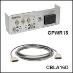
- GPWR15 Power Supply: ±15 V Power Supply for Single- and Dual-Axis Systems; One Supply Can Power up to Two Galvos
- XG Series Scan Heads
- QS, SS, and SP Series VantagePro® Galvanometer Scanners
- BLINK Focusers
- GPWR15 Power Supply Specs:
- Open Frame Requires Cables to be Soldered In
- Input: 100-120 or 220-240 VAC
- Output: ±15 V @ 5 A (150 W Max Power)
- Operating Temperature: 0 to 50 °C
- Dimensions: 14.0" x 4.9" x 3.5" (356 mm x 124 mm x 90 mm)
- CBLA16D: Command Cable for XG Series Scan Heads
- CBLPA16F: Power Cable for XG Series Scan Heads
The GPWR15 Power Supply is a low noise, linear supply designed to minimize electrical interference for maximum system resolution. The compatible systems include the XG Series Scan Heads, the QS, SS, and SP Series Galvanometers Scanners, and the BLINK Focusers. This power supply delivers ±15 VDC at 5 A and is configured to accept a mains voltage of 100 - 120 or 220 - 240 VAC. The GPWR15 power supply has an open frame, allowing the user to solder the compatible power cable into the system.
The CBLA16D Command Cable can be used to connect a compatible controller to the XG series scan heads. The cable has a fourteen pin connector on each end. For more information on finding a compatible controller, refer to the Controller Options tab above. The CBLA16F Power Cable connects the GPWR15 power supply to the XG series scan heads. The cable has a fourteen pin connector one end for compatability with the XG series scan heads along with three bare wires for soldering to the GPWR15 power supply.

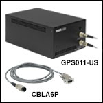
- GPS011 Series: ±15 V Power Supply for Single- and Dual-Axis Systems; One Supply Can Power up to Two Galvos
- XG Series Scan Heads
- QS7, QS10, QS15, and QS20 Series VantagePro® Galvanometer Scanners
- BLINK Focusers
- GPS011 Series Specs:
- Enlcosed Unit Allows Cables to Directly Connect to the System
- Switchable Input: 100 V AC / 50 or 60 Hz, 115V AC / 60 Hz, 230 V AC / 50 Hz
- Output: ±15 VDC @ 3 A
- Operating Temperature: 5 to 40 °C
- Dimensions: 7.05" x 10.79" x 4.8" (179 mm x 274 mm (max) x 122 mm)
- CBLA6P: Power Cable for XG Series Scan Heads
The GPS011 Series Power Supply is a low noise, linear supply designed to minimize electrical interference for maximum system resolution for 1D and 2D galvanometer systems. The compatible systems include the XG Series Scan Heads, the QS7, QS10, QS15, and QS20 Series Galvanometers Scanners, and the BLINK Focusers. These power supplies deliver ±15 VDC at 3 A and are configured to accept a mains voltage of 115 VAC (for GPS011-US), 230 VAC (for GPS011-EC), or 100 VAC (for GPS011-JP). The GPS011 units are enclosed, allowing for direct connection with the compatible power cable without soldering.
The CBLA16D Command Cable can be used to connect a compatible controller to the XG series scan heads. The cable has a fourteen pin connector on each end. For more information on finding a compatible controller, refer to the Controller Options tab above. The CBLA6P Power Cable can be used to connect the GPS011 series galvo system linear power supplies to the XG series scan heads. The cable has a three-pin circular connector on one end for compatibility with the GPS011 series power supplies and a nine pin D-Sub connector on the other end for compatibility with the XG series scan heads.

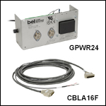
- GPWR24 Power Supply: ±24 V Power Supply for Single- and Dual-Axis Systems; One Supply Can Power up to Two Galvos
- DCB Series Scan Heads
- QS Series VantagePro® Galvanometer Scanners
- GPWR24 Power Supply Specs:
- Open Frame Requires Cables to be Soldered In
- Input: 100-120 or 220-240 VAC
- Output: ±24 V @ 2.4 A (115 W Max Power)
- Operating Temperature: 0 to 50 °C
- Dimensions: 9.38" x 4.87" x 3.28" (238.3 mm x 123.7 mm x 83.3 mm)
- CBLA16F: Command and Power Cables for DCB Series Scan Heads
The GPWR24 Series Power Supply is a low noise, linear supply designed to minimize electrical interference for maximum system resolution. The compatible systems include the DCB Series Scan Heads and the QS Series Galvanometers Scanners. It delivers ±24 VDC at 2.4 A and is configured to accept a mains voltage of 100 - 120 or 220 - 240 VAC. The GPWR24 power supply has an open frame, allowing the user to solder the compatible power cable into the system.
The CBLA16F Command and Power Cables can be used to connect the GPWR24 power supply to the DCB series scan heads. The cable has a fourteen pin connector on each end along with three bare wires for soldering to the GPWR24 power supply unit. For more information on finding a compatible controller, refer to the Controller Options tab above.
 Products Home


 Zoom
Zoom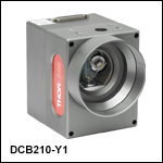

 2-Axis Galvo Scan Heads