 Products Home
LiTaO3 Amplified Pyroelectric Detector

- Wavelength Range from 0.6 µm to 16 µm
- Flat Response Over Wavelength Range
- Adjustable Gain Selection (0 dB to 35 dB)
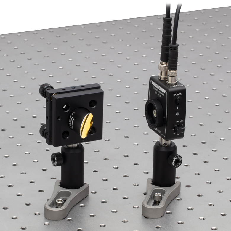
An MC1F10HP Blade on a Chopper Head
(Included in the MC2000B System) can be used with a CW source to produce a signal on the PDA13A2 pyroelectric detector.
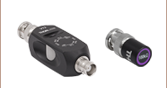
PDA13L2
Switchable-Gain
Pyroelectric Detector
Side View
(8 Gain Steps)


Please Wait
| MIR Detector Selection Guidea | ||||
|---|---|---|---|---|
| Item # (Detector) | Detector Type | Wavelength Range |
Maximum Bandwidth |
Thermoelectric Cooler |
| PDA10DT (InGaAs) | Photodiode | 0.9 - 2.57 µm | 1,000 kHz | Yes |
| PDA10D2 (InGaAs) | Photodiode | 0.9 - 2.6 µm | 25,000 kHz | No |
| PDA10PT (InAsSb) | Photodiode | 1.0 - 5.8 µm | 1,600 kHz | Yes |
| PDA07P2 (InAsSb) | Photodiode | 2.7 - 5.3 µm | 9 MHz | No |
| PDAVJ8 (HgCdTe) | Photodiode | 2.0 - 8.0 µm | 100 MHz | No |
| PDAVJ10 (HgCdTe) | Photodiode | 2.0 - 10.6 µm | 100 MHz | No |
| PDAVJ5 (HgCdTe) | Photodiode | 2.7 - 5.0 µm | 1 MHz | No |
| PDA13L2 (LiTaO3) | Pyroelectric | 0.6 - 16 µm | 10 kHz | No |
Features
- Wavelength Range 0.6 µm to 16 µm
- Low-Noise Amplification with Switchable Gain
- For Pulsed or Chopped Light Sources
- Modulation Bandwidth from 10 Hz to 10 kHz
- Flat Frequency Response Between 100 Hz and 1 kHz
- Detector Active Area: 1.3 mm2 (Ø1.3 mm)
- Flat Response Over Entire Wavelength Range
- External SM1 (1.035"-40 Threads and Internal SM05 (0.535"-40) Threads
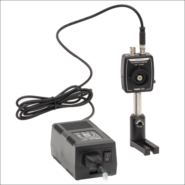
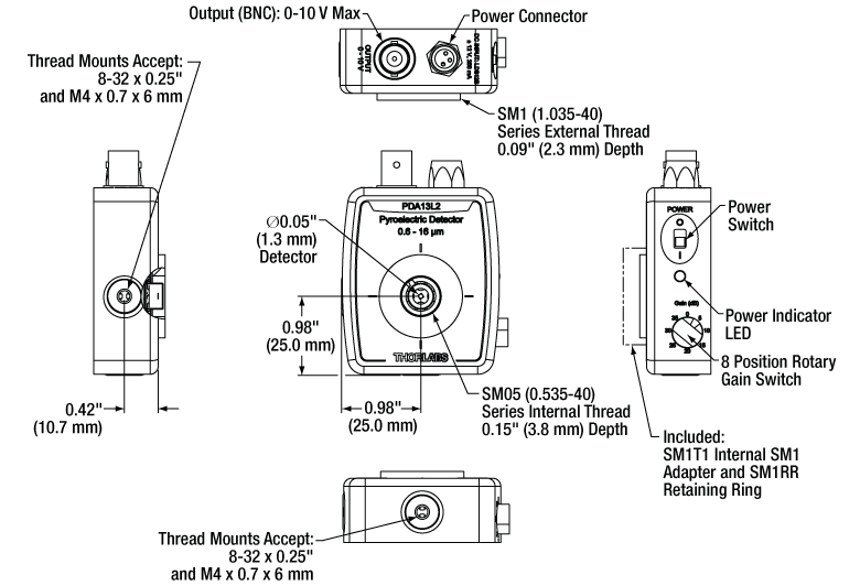
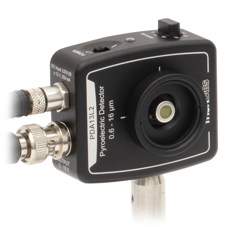
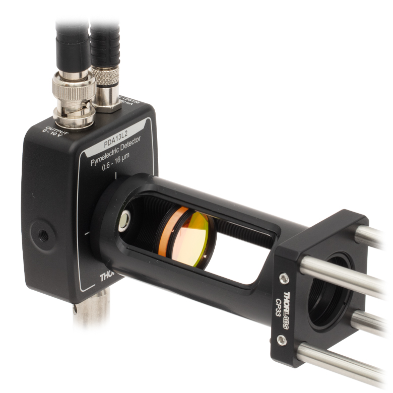
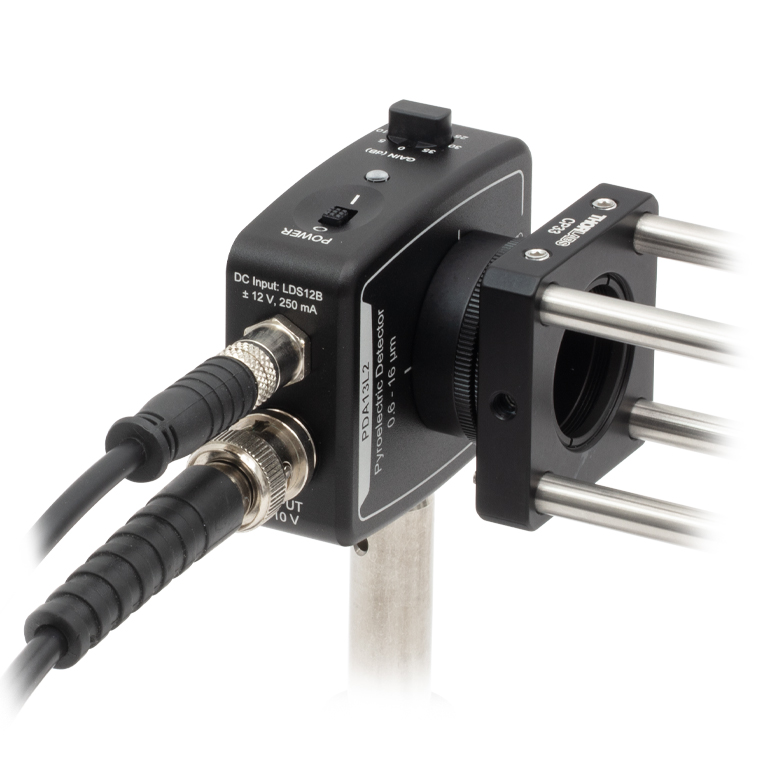
Thorlabs' PDA13L2 is a low-noise, amplified, switchable-gain, pyroelectric LiTaO3 (lithium tantalate) detector for use with pulsed light signals between 0.6 µm and 16 µm. A rotary switch on the side of the housing allows for the signal amplification to be adjusted in 8 gain steps of 5 dB from 0 dB to 35 dB. The signal output is provided via a BNC connector and is capable of driving 50 Ω and high impedance loads with a maximum output voltage of 5 V and 10 V, respectively. The low-profile housing enables use in optical paths with space constraints.
Click to Enlarge
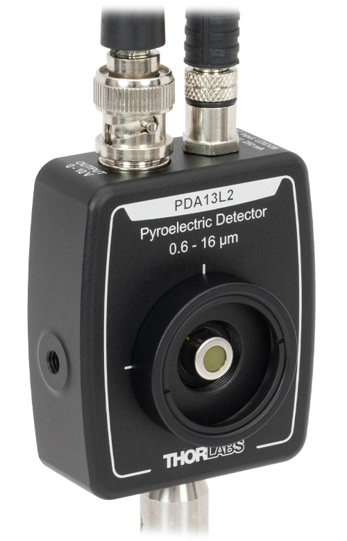
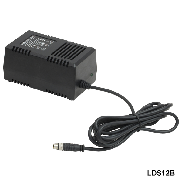
Each PDA13L2 detector is shipped with an LDS12B power supply.
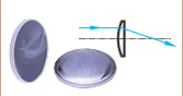
Click to Enlarge
The MPD149-M01 Off-Axis Parabolic Mirror can be used to focus a collimated source between 0.8 µm and 20 µm without introducing chromatic aberration, making it ideal for use with the PDA13L2 detector.
Pyroelectric materials produce a voltage difference in response to a change in temperature. The PDA13L2 pyroelectric detector utilizes an LiTaO3 (lithium tantalate) sensor coated with a black metal absorber and packaged behind an uncoated ZnSe (zinc selenide) window. The metal absorber and LiTaO3 sensor absorbs the incident light causing a change in temperature and therefore a voltage difference. Since a change in temperature is required to produce a signal, the detector requires a modulated or pulsed light source. CW sources will not produce a signal once the detector reaches thermal equilibrium. Using an optical chopper such as the MC2000B optical chopper system or another form of modulation with a frequency from 10 Hz up to 10 kHz is recommended. The frequency response for the PDA13L2 detector is flat between 100 Hz and 1000 Hz.
The lithium tantalate material has a generally flat response curve over the entire operating wavelength range, making the PDA13L2 detector useful for applications with broadband signals or with light from visible to MIR wavelengths. For more information on the ZnSe window transmission, the absorbance of the black metal coating and LiTaO3 substrate, and the frequency response, please see the Performance Graphs in the Specs tab.
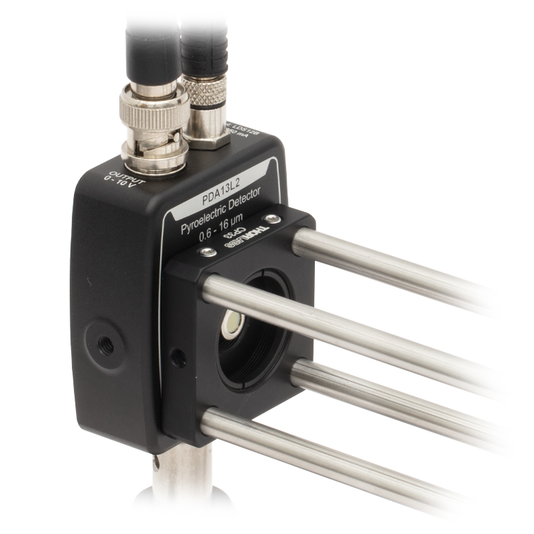
Each housing features external SM1 (1.035"-40) threading, internal SM05 (0.535"-40) threading, and two universal mounting holes that accept both 8-32 and M4 x 0.7 threads, allowing for either vertical or horizontal post mounting. Additionally, an SM1T1 internally SM1-threaded coupler and SM1RR retaining ring are included with each detector, enabling convenient mounting of SM1-compatible accessories, optics, and cage assembly accessories. The internal SM05 threading is only suitable for mating to an externally SM05-threaded lens tube (components such fiber adapters cannot be threaded onto the SM05 threading). Externally SM1-threaded adapters should be mated to the included SM1T1 coupler, while internally SM1-threaded adapters can be mated directly to the housing. The detector was designed to allow for maximum accessibility to the photodetector by having the active area surface of the diode flush with the outside PDA housing. When using fiber adapters or other optics, make sure that the components do not crash into the detector. See the Mounting Options tab for more details.
| Gain Performance Specificationsa | |||||
|---|---|---|---|---|---|
| 0 dB Setting | 20 dB Setting | ||||
| Gainb | Hi-Z | 3.00 V/V ± 2% | Gainb | Hi-Z | 29.7 V/V ± 2% |
| 50 Ω | 1.50 V/V ±2% | 50 Ω | 14.9 V/V ± 2% | ||
| Bandwidth | 10 Hz - 10 kHz | Bandwidth | 10 Hz - 10 kHz | ||
| Noise (RMS) | 185 µV | Noise (RMS) | 1.45 mV | ||
| NEP | 32.5 nW/√Hz | NEP | 32.1 nW/√Hz | ||
| Offset | ±10 mV (Max) | Offset | ±10 mV (Max) | ||
| 5 dB Setting | 25 dB Setting | ||||
| Gainb | Hi-Z | 5.32 V/V ± 2% |
Gainb | Hi-Z | 53.3 V/V ± 2% |
| 50 Ω | 2.66 V/V ± 2% | 50 Ω | 26.7 V/V ± 2% | ||
| Bandwidth | 10 Hz - 10 kHz | Bandwidth | 10 Hz - 10 kHz | ||
| Noise (RMS) | 320 µV | Noise (RMS) | 2.20 mV | ||
| NEP | 33.9 nW/√Hz | NEP | 28.3 nW/√Hz | ||
| Offset | ±10 mV (Max) | Offset | ±10 mV (Max) | ||
| 10 dB Setting | 30 dB Setting | ||||
| Gainb | Hi-Z | 9.45 V/V ± 2% | Gainb | Hi-Z | 94.1 V/V ± 5% |
| Hi-Z | 4.73 V/V ± 2% | 50 Ω | 47.1 V/V ± 5% | ||
| Bandwidth | 10 Hz - 10 kHz | Bandwidth | 10 Hz - 10 kHz | ||
| Noise (RMS) | 550 µV | Noise (RMS) | 2.95 mV | ||
| NEP | 31.4 nW/√Hz | NEP | 26.4 nW/√Hz | ||
| Offset | ±10 mV (Max) | Offset | ±10 mV (Max) | ||
| 15 dB Setting | 35 dB Setting | ||||
| Gainb | Hi-Z | 16.8 V/V ± 2% | Gainb | Hi-Z | 170 V/V ± 5% |
| 50 Ω | 8.4 V/V ± 2% | 50 Ω | 85.0 V/V ± 5% | ||
| Bandwidth | 10 Hz - 10 kHz | Bandwidth | 10 Hz - 10 kHz | ||
| Noise (RMS) | 920 µV | Noise (RMS) | 3.75 mV | ||
| NEP | 31.8 nW/√Hz | NEP | 22.6 nW/√Hz | ||
| Offset | ±10 mV (Max) | Offset | ±10 mV (Max) | ||
| Item # | PDA13L2 | |
|---|---|---|
| Electrical | ||
| Detector | Pyroelectric Lithium Tantalate (LiTaO3) | |
| Detector Active Area | 1.3 mm2 (Ø1.3 mm) | |
| Wavelength Range | 0.6 to 16 µm | |
| Window Material | ZnSe (0.8 mm Thick) | |
| Field of View | 85° (Typical) | |
| Responsivity (500 K, 100 Hz, 25 °C)a | 120 V/W | |
| Output Impedance | 50 Ω | |
| Max Output Current (Iout) | 100 mA | |
| Load Impedance | 50 Ω to Hi-Z | |
| Gain Adjustment Range | 0 dB to 35 dB | |
| Gain Steps | 8 Steps (5 dB Increments) | |
| Output Voltage | 50 Ω | 0 to 5 V |
| Hi-Z | 0 to 10 V | |
| Typical Performance Graphsb | ||
| General | ||
| On/Off Switch | Slide | |
| Gain Switch | 8 Position Rotary | |
| Output | BNC (DC Coupled) | |
| Package Sizeb | 2.79" x 1.96" x 0.89" (70.9 mm x 49.9 mm x 22.5 mm) |
|
 |
||
| Detector Surface Depthc | 0.09" (2.2 mm) | |
| Weightd | 0.10 kg | |
| Accessories | SM1T1 Coupler SM1RR Retaining Ring SM1EC2B Dust Cap LDS12B Power Supply |
|
| Operating Temperature | 10 to 40 °C | |
| Storage Temperature | -20 to 70 °C | |
| AC Power Supply | AC - DC Converter | |
| Input Powere | 31 W 100 V / 120 V / 230 V, 50 - 60 Hz |
|
Mounting Options for the PDA13L2 Amplified Pyroelectric Detector
The PDA13L2 detector is compatible with our SM1- and SM05-threaded lens tubes, TR series posts, and can be integrated into cage systems. Because of the wide range of mounting options, the best method for mounting the housing in a given optical setup is not always obvious. The pictures and text in this tab will discuss some of the common mounting solutions. As always, our Tech Support staff is available for individual consultation.
TR Series Ø1/2" Post System
The PDA13L2 housing can be mounted vertically or horizontally on a TR Series Post using either an 8-32 or M4 x 0.7 threaded screw, as the housing features universal 8-32 / M4 x 0.7 threads.
| PDA13L2 detector mounted vertically on a TR series post. In this configuration, the output and power cables are oriented vertically and away from the optic table, facilitating a neater optical setup. | PDA13L2 detector mounted horizontally on a TR series post. In this configuration, the on/off switch and gain selector dial is conveniently oriented on the top of the detector. |
Lens Tube System
The PDA13L2 housing includes a detachable SM1T1 internally SM1-threaded coupler that allows for mounting additional externally SM1-threaded optical components along the optical axis.
The external SM1 and internal SM05 threads on the pyroelectric detector housing make it compatible with our SM1 lens tube system and accessories. Two particularly useful accessories include the SM-threaded irises and the SM-compatible IR and visible alignment tools. Also available are fiber optic adapters for use with connectorized fibers.
| PDA13L2 detector mounted onto an SM1L30C Ø1" Slotted Lens Tube, which is housing an LA7656-E4 ZnSe lens. The lens tube is attached to a 30 mm cage system via a CP33 SM1-Threaded 30 mm Cage Plate. This arrangement allows easy access for optic adjustment and signal alignment. |
Cage System
The simplest method for attaching the PDA13L2 housing to a cage plate is to remove the SM1T1 coupler attached to the front of the detector housing and use the external SM1 threads. A cage plate, such as the CP33 30 mm cage plate, can be directly attached to the SM1 threads. Then an SM1RR retaining ring, included with the CP33 cage plate, can be threaded using a spanner wrench into the CP33 cage plate to ensure it is tightened to the desired location and square with the pyroelectric detector housing.
This method for attaching the PDA13L2 detector housing to a cage plate does not allow much freedom in determining the orientation of the detector; however, it has the benefit of not needing an adapter piece, and it allows the diode to be as close as possible to the cage plate, which can be important in setups where the light is divergent.
For more freedom in choosing the orientation of the PDA13L2 housing, an SM1T2 coupler can be threaded into the included SM1T1 adapter allowing a CP33 cage plate to be threaded onto the exposed SM1-threading and secured using one of the two locking rings included with the SM1T2 coupler.
The PDA13L2 detector housing can also be connected to a 16 mm cage system by threading one side of an SM05T2 coupler to the detector housing and the other to an SP02 cage plate.
| This picture shows a PDA13L2 detector attached to a CP33 cage plate after removing the SM1T1. The retaining ring from the SM1T1 was used to make the orientation of the detector square with the cage plate. | This picture shows a PDA13L2 detector attached to a CP33 cage plate using an SM1T2 adapter in addition to the SM1T1 coupler that comes with the detector. |
Male (Power Cables)
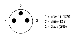
Shown above is the pin diagram for the power cable on the LDS12B power supply that is used with the PDA13L2 detector.
Female Power IN (Photodetector)
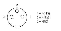
Pin Diagram for PDA13L2 Power Connector
BNC Female Output (Photodetector)
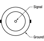
PDA13L2 Signal Output
50 Ω: 0 - 5 V
Hi-Z: 0 - 10 V
Pulsed Laser Emission: Power and Energy Calculations

Determining whether emission from a pulsed laser is compatible with a device or application can require referencing parameters that are not supplied by the laser's manufacturer. When this is the case, the necessary parameters can typically be calculated from the available information. Calculating peak pulse power, average power, pulse energy, and related parameters can be necessary to achieve desired outcomes including:
- Protecting biological samples from harm.
- Measuring the pulsed laser emission without damaging photodetectors and other sensors.
- Exciting fluorescence and non-linear effects in materials.
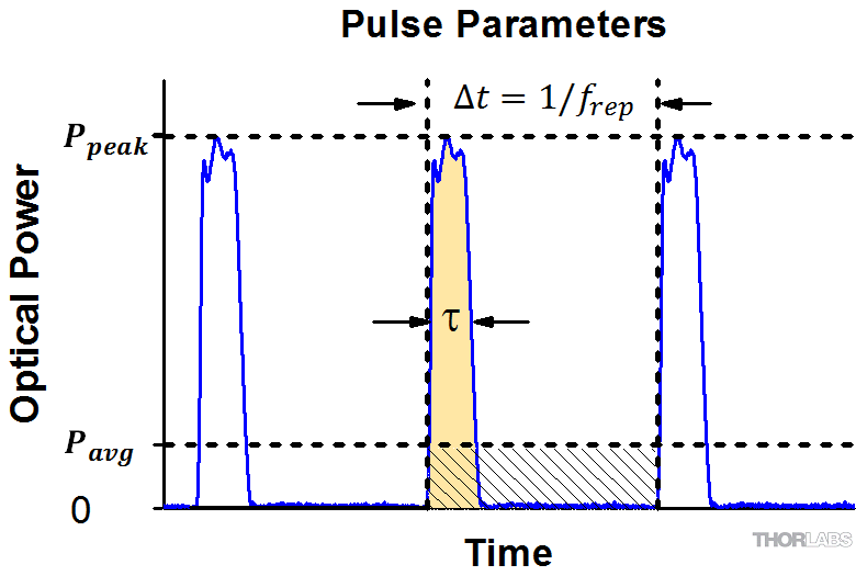
Pulsed laser radiation parameters are illustrated in Figure 1 and described in the table. For quick reference, a list of equations are provided below. The document available for download provides this information, as well as an introduction to pulsed laser emission, an overview of relationships among the different parameters, and guidance for applying the calculations.
|
Equations: |
||||
 |
and |  |
||
 |
||||
 |
||||
 |
||||
Peak power and average power calculated from each other: |
||||
 |
and |  |
||
| Peak power calculated from average power and duty cycle*: | ||||
 |
*Duty cycle ( ) is the fraction of time during which there is laser pulse emission. ) is the fraction of time during which there is laser pulse emission. |
|||
Click to Enlarge
Figure 1: Parameters used to describe pulsed laser emission are indicated in the plot (above) and described in the table (below). Pulse energy (E) is the shaded area under the pulse curve. Pulse energy is, equivalently, the area of the diagonally hashed region.
| Parameter | Symbol | Units | Description | ||
|---|---|---|---|---|---|
| Pulse Energy | E | Joules [J] | A measure of one pulse's total emission, which is the only light emitted by the laser over the entire period. The pulse energy equals the shaded area, which is equivalent to the area covered by diagonal hash marks. | ||
| Period | Δt | Seconds [s] | The amount of time between the start of one pulse and the start of the next. | ||
| Average Power | Pavg | Watts [W] | The height on the optical power axis, if the energy emitted by the pulse were uniformly spread over the entire period. | ||
| Instantaneous Power | P | Watts [W] | The optical power at a single, specific point in time. | ||
| Peak Power | Ppeak | Watts [W] | The maximum instantaneous optical power output by the laser. | ||
| Pulse Width |  |
Seconds [s] | A measure of the time between the beginning and end of the pulse, typically based on the full width half maximum (FWHM) of the pulse shape. Also called pulse duration. | ||
| Repetition Rate | frep | Hertz [Hz] | The frequency with which pulses are emitted. Equal to the reciprocal of the period. | ||
Example Calculation:
Is it safe to use a detector with a specified maximum peak optical input power of 75 mW to measure the following pulsed laser emission?
- Average Power: 1 mW
- Repetition Rate: 85 MHz
- Pulse Width: 10 fs
The energy per pulse:

seems low, but the peak pulse power is:

It is not safe to use the detector to measure this pulsed laser emission, since the peak power of the pulses is >5 orders of magnitude higher than the detector's maximum peak optical input power.
| Posted Comments: | |
Andrew Nelson
(posted 2024-01-07 11:04:35.7) What is the relationship between the PDA13L2 Transmission % and Spectral Responsivity, or Quantum Efficiency. Also is there data for 6um to 16um. I only see raw data form 2000 nm to 20000 nm. Is that not out of the range of the PDA13L2? As it maxes out at 16000 nm? ksosnowski
(posted 2024-01-08 03:03:44.0) Hello Andrew, thanks for reaching out to Thorlabs. The Spectral Responsivity depends on the product of the PDA13L2 Window Transmission and the Spectral Absorption. Though we expect the device to be most useful in the 0.6um to 16um range, we have taken data on window and surface absorption over a wider range of wavelengths as seen in the raw data. Since the absorption and window transmission will decrease outside the normal range, the lowered effective response leads to a worse SNR there which some applications cannot tolerate. |
The following table lists Thorlabs' selection of photodiodes, photoconductive, and pyroelectric detectors. Item numbers in the same row contain the same detector element.

 Zoom
Zoom| Item # | Housing Featuresa | Wavelength Range | Responsivityb | Bandwidth | Gainc | NEPc,d | Graphse |
|---|---|---|---|---|---|---|---|
| PDA13L2 | |
0.6 - 16 µm | 120 V/W | 10 Hz - 10 kHz | 3.00 V/V ± 2% (Hi-Z) 1.50 V/V ± 2% (50 Ω) |
32.5 nW/√Hz |

 Zoom
ZoomLDS12B Male Power Cable
- Replacement Power Supply for the PDA13L2 Amplified Pyroelectric Detector Sold Above
- ±12 VDC Power Output
- Current Limit Enabling Short Circuit and Overload Protection
- On / Off Switch with LED Indicator
- Switchable AC Input Voltage (100, 120, or 230 VAC)
- 2 m (6.6 ft) Cable with LUMBERG RSMV3 Male Connector
- UL and CE Compliant
The LDS12B ±12 VDC Regulated Linear Power Supply is intended as a replacement for the supply that comes with the PDA13L2 pyroelectric detector sold above. The cord has three pins: ground, +12 V, and -12 V (see diagram to the right). A region-specific power cord is shipped with the LDS12B power supply based on your location. This power supply can also be used with the Thorlabs' other PDA and PDF detectors with the same connector as well as the PDB series of balanced photodetectors, PMM series of photomultiplier modules, APD series of avalanche photodetectors, and the FSAC autocorrelator for femtosecond lasers.

 Zoom
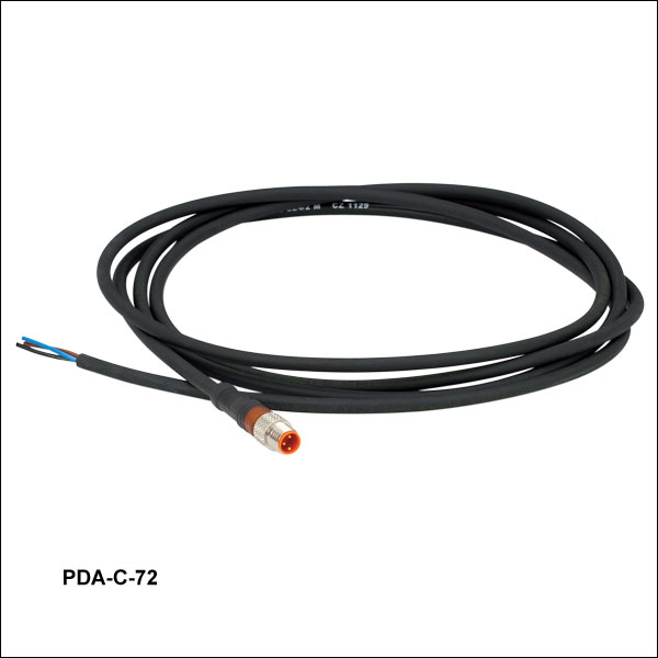
Zoom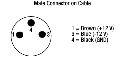
The PDA-C-72 power cord is offered for the PDA line of amplified photodetectors when using with a power supply other than the one included with the detector. The cord has tinned leads on one end and a PDA-compatible 3-pin connector on the other end. It can be used to power the PDA series of amplified photodetectors with any power supply that provides a DC voltage. The pin descriptions are shown to the right.