 Products Home / Motion Control Electronics / DC Servo Controllers / Brushless DC Motor Controller Module
Brushless DC Motor Controller Module
- Two Motor Drive Channels
- Supports 3-Phase, Brushless DC Servo Motors (5.2 A Peak Total Output) with Encoder Feedback
- Seamless Operation with Thorlabs and 3rd Party Motors
MBD602
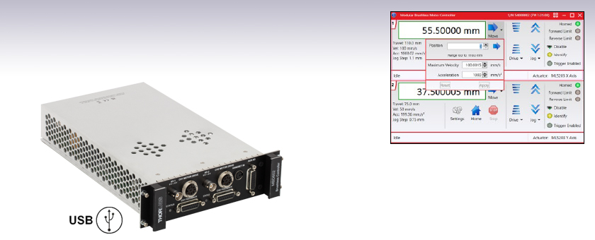
Kinesis® Software GUI


Please Wait
| Rack System Modules |
|---|
| 2-Channel Piezo Controller Module |
| 2-Channel Stepper Motor Controller Module |
| 2-Channel NanoTrak® Auto-Alignment Module |
| 2-Channel Brushless DC Motor Controller Module |
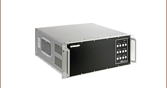
| USB Motion Control 19" Rack Chassis |
| All Thorlabs' Rack System Modules require the use of the MMR601 or MMR602 Rack System Enclosure. Independent operation of the modules outside the enclosure is not possible. |
Features
- Two Brushless DC Motor Drive Channels
- Supports Thorlabs' Range of 3-Phase DC Brushless Motors up to 100 W Peak
- Incremental Encoder Feedback for Closed-Loop Velocity and Position Control
- Requires the MMR601 or MMR602 Motion Control 19" Modular Rack System Enclosure
- USB Plug and Play Through Rack System Enclosure for Multi-Axis Expansion
- Motor Control I/O Port (Jogging, Interlocks)
- Full Kinesis® Software Control Suite Included
- New Features Supported by Kinesis:
- Fast Position Input/Output Triggering
- Synchronized Moves
- Dynamic PID Settings
- Intuitive Software Graphical Control Panels
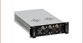
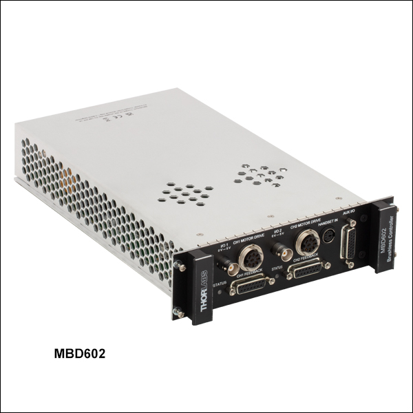
The MBD602 Controller Module is a dual-channel, high-resolution, brushless DC motor driver designed specifically for use with the highly flexible MMR601 or MMR602 Motion Control 19" Modular Rack System. It can drive Thorlabs' range of 3-phase brushless DC servo motors up to 100 W, with or without encoder feedback. With our robust Kinesis softrware package, fast input and output triggering makes the MBD602 a versatile building block for complex control systems that can be customized to fit diverse application needs.
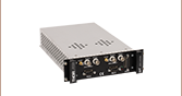
Up to six MBD602 modules can be fitted to a given rack system, providing a scalable motion control solution for multi-axis motion control applications. For stand-alone controller options, please see the table below. Within an MMR601 or MMR602 Rack enclosure, this unit can be used with a PC via USB connection. Multiple modules can be connected to a single PC via standard USB hub technology for multi-axis motion control applications. Coupling this with the user friendly Kinesis software allows the user to get up and running very quickly. For example, all relevant operating parameters are set automatically for Thorlabs' stage/actuator products. Advanced custom motion control applications and sequences are also possible using the extensive .NET programming environment, which is described in more detail on the Kinesis Software and Kinesis Tutorials tabs.
Triggering Capabilities
The MBD602 controller is equipped with powerful input and output position triggering capabilities. With a latency under 102 µs, the intervals to send live position triggers are user-defined, so the user can set near-encoder level trigger points (down to 100 - 200 nm) for live data capture or feedback. The position trigger engine sends thousands of pulses while scanning, providing the user with a versatile platform for highly customizable image mapping to suit a diverse range of applications. With our Kinesis software, the user can define a start point, interval for pulses, number of pulses, and pulse width of the output trigger. As an example, to image a 5 mm x 5 mm sample, the user can define the edge of the sample and then have the system raster scan across the sample, taking images at any desired interval. With the trigger interval matched to the system's field of view, the images can be digitally combined to efficiently reconstruct a high magnification view of the whole sample.
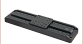
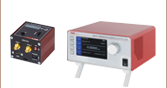
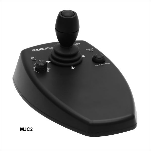
Optional Joystick
An optional 2-axis joystick (Item # MJC2) is also available below for tactile, manual positioning of a stage. See the manuals, found by clicking on the red Docs icons (![]() ), for more information on using the joystick.
), for more information on using the joystick.
Cabling
Cables for connecting actuators or stages to the controller are shipped with the actuators or stages, not the controller. If you need help identifying the appropriate replacement cable, please contact Tech Support.
| Other Brushless DC Motor Controllers | |||
|---|---|---|---|
| K-Cube Single-Channel Controller | 1-, 2-, and 3-Channel Benchtop Controller | 19" Rack-Mounted Controller | Modular 2-Channel Rack System Module |
| Item # | MBD602 |
|---|---|
| Number of Channels | 2 |
| Motor Drive Connector | 8-Pin DIN-Type, Female (Motor Phase Outputs, Stage ID Input) |
| Feedback Connector | 15-Pin D-Type Female |
| Brushless Continuous Current Output | 2.5 A per Channel (5.0 A Max All-Channel Output) |
| Brushless Peak Current Output | 4.0 A per Channel (5.2 A Max All-Channel Output) |
| Pulse-Width Modulation Frequency | 20 kHz |
| Operating Modes | Position and Velocity |
| Control Algorithm | 16-Bit Digital PID Servo Loop with Velocity and Acceleration Feed Forward |
| Velocity Profile | Trapezoidal |
| Position Count | 32 Bit |
| Position Feedback | Incremental Encoder |
| Encoder Bandwidth | 2.5 MHz (10 M Counts/sec) |
| Encoder Supply | 5 V |
| AUX Control Connector | 26-Way High Density D-Type Female (User Digital IO, 5 V O/P) |
| Input Power Requirements | Power: 250 VA Voltage: 100 to 240 VAC Frequency: 47 to 63 Hz |
| Dimensions | 187 mm x 286.6 mm x 50.4 mm (7.36" x 11.28" x 1.98") |
| Weight | 0.9 kg (1.98 lbs) |
| Compatible Motor Specs | 3-Phase DC Brushless Motors with Peak Power: 100 W, Coil Resistance: 0.1 to 100 Ω, Coil Inductance (Nominal): 1 to 100 mH, and Rated Phase Current (Nominal): 100 mA to 5 A |
| Item # | MMR601 & MMR602 |
|---|---|
| Enclosure | Standard 19" Rack, 4U High |
| Module Bays | 6 Modular Slots, Back Panel Access |
| Communications | USB 1.1 Interface |
| Power Input | |
| Voltage | 85-264 VAC |
| Frequency | 47-63 Hz |
| Power | 800 W |
| Fuse | 10 A |
| Dimensions (W x D x H): | 480 x 448 x 183 mm (19.0" X 17.6" X 7.0") |
| Weight | 16 kg (35.2 lbs) |
MOTOR DRIVE
8-Pin DIN-Type, Female
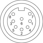
| Pin | Description | Pin | Description |
|---|---|---|---|
| 1 | Motor Phase B | 5 | Stage ID |
| 2 | GND | 6 | Enable |
| 3a | Motor Phase D | 7 | Motor Phase C |
| 4 | Motor Phase A | 8a | +5 V |
FEEDBACK
15-Pin D-Type, Female
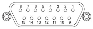
| Pin | Description | Pin | Description |
|---|---|---|---|
| 1 | Not Connected | 9 | GND |
| 2 | GND | 10 | Limit Switch + |
| 3 | Not Connected | 11 | Limit Switch - |
| 4 | Index - | 12 | Index + |
| 5 | QB - | 13 | QB + |
| 6 | QA - | 14 | QA + |
| 7a | 5 V | 15 | Not Connected |
| 8a | 5 V |
HANDSET
Mini DIN Female
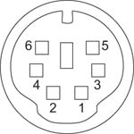
| Pin | Description | Pin | Description |
|---|---|---|---|
| 1 | RX (Controller Input) | 4b | Supply Voltage for Handset 5 V |
| 2a | Ground | 5 | TX (Controller Output) |
| 3a | Ground | 6a | Ground |
AUX I/O
26-Way High Density D-Type, Female
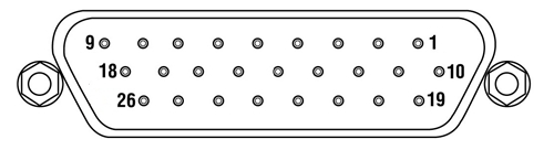
| Pin | Description | Function | Pin | Description | Function | Pin | Description | Function |
|---|---|---|---|---|---|---|---|---|
| 1a | Digital I/P 3 |
- | 10a | Digital O/P 3 |
- | 19c | Ground | - |
| 2a | Digital I/P 2 |
- | 11a | Digital O/P 2 |
- | 20e | Digital O/P 2+ |
Motor #1 Encoder B+ |
| 3a | Digital I/P 1 |
- | 12a | Digital O/P 1 |
- | 21e | Digital O/P 2- |
Motor #1 Encoder B- |
| 4a | Digital I/P 0 |
- | 13a | Digital O/P 0 |
- | 22e | Ground | - |
| 5e | Digital O/P 6- |
Motor #2 Encoder A- | 14e | Digital O/P 4+ |
Motor #2 Encoder IX+ | 23d | 5 V | - |
| 6e | Digital O/P 6+ |
Motor #2 Encoder A+ | 15e | Digital O/P 4- |
Motor #2 Encoder IX- | 24e | Digital O/P 1+ |
Motor #1 Encoder IX+ |
| 7e | Digital O/P 5+ |
Motor #2 Encoder B+ | 16e | Digital O/P 3- |
Motor #1 Encoder A- | 25e | Digital O/P 1- |
Motor #1 Encoder IX- |
| 8e | Digital O/P 5- |
Motor #2 Encoder B- | 17e | Digital O/P 3+ |
Motor #1 Encoder A+ | 26c | Ground | - |
| 9b | RS-232 RX | - | 18b | RS-232 TX | - |
Software
Kinesis Version 1.14.50
The Kinesis Software Package, which includes a GUI for control of Thorlabs' Kinesis system controllers.
Also Available:
- Communications Protocol

Kinesis GUI Screen
Thorlabs offers the Kinesis® software package to drive our wide range of motion controllers. The software can be used to control devices in the Kinesis family, which covers a wide variety of motion controllers ranging from small, low-powered, single-channel drivers (such as the K-Cubes™) to high-power, multi-channel benchtop units and modular 19" rack nanopositioning systems (the MMR60x Rack System).
The Kinesis Software features .NET controls which can be used by 3rd party developers working in the latest C#, Visual Basic, LabVIEW™, or any .NET compatible languages to create custom applications. Low-level DLL libraries are included for applications not expected to use the .NET framework and APIs are included with each install. A Central Sequence Manager supports integration and synchronization of all Thorlabs motion control hardware.
By providing this common software platform, Thorlabs has ensured that users can mix and match any of our motion control devices in a single application, while only having to learn a single set of software tools. In this way, it is perfectly feasible to combine any of the controllers from single-axis to multi-axis systems and control all from a single, PC-based unified software interface.
The software package allows two methods of usage: graphical user interface (GUI) utilities for direct interaction with and control of the controllers 'out of the box', and a set of programming interfaces that allow custom-integrated positioning and alignment solutions to be easily programmed in the development language of choice.
Legacy Software
Select products are still capable of running the legacy APT™ software package. Information on software compatibility can be found in the product documentation ( ), and additional details about the APT software can be found here.
Thorlabs' Kinesis® software features new .NET controls which can be used by third-party developers working in the latest C#, Visual Basic, LabVIEW™, or any .NET compatible languages to create custom applications.
C#
This programming language is designed to allow multiple programming paradigms, or languages, to be used, thus allowing for complex problems to be solved in an easy or efficient manner. It encompasses typing, imperative, declarative, functional, generic, object-oriented, and component-oriented programming. By providing functionality with this common software platform, Thorlabs has ensured that users can easily mix and match any of the Kinesis controllers in a single application, while only having to learn a single set of software tools. In this way, it is perfectly feasible to combine any of the controllers from the low-powered, single-axis to the high-powered, multi-axis systems and control all from a single, PC-based unified software interface.
The Kinesis System Software allows two methods of usage: graphical user interface (GUI) utilities for direct interaction and control of the controllers 'out of the box', and a set of programming interfaces that allow custom-integrated positioning and alignment solutions to be easily programmed in the development language of choice.
For a collection of example projects that can be compiled and run to demonstrate the different ways in which developers can build on the Kinesis motion control libraries, click on the links below. Please note that a separate integrated development environment (IDE) (e.g., Microsoft Visual Studio) will be required to execute the Quick Start examples. The C# example projects can be executed using the included .NET controls in the Kinesis software package (see the Kinesis Software tab for details).
 |
Click Here for the Kinesis with C# Quick Start Guide Click Here for C# Example Projects Click Here for Quick Start Device Control Examples |
|
LabVIEW
LabVIEW can be used to communicate with any Kinesis- or APT-based controller via .NET controls. In LabVIEW, you build a user interface, known as a front panel, with a set of tools and objects and then add code using graphical representations of functions to control the front panel objects. The LabVIEW tutorial, provided below, provides some information on using the .NET controls to create control GUIs for Kinesis- and APT-driven devices within LabVIEW. It includes an overview with basic information about using controllers in LabVIEW and explains the setup procedure that needs to be completed before using a LabVIEW GUI to operate a device.
 |
Click Here to View the LabVIEW Guide Click Here to View the Kinesis with LabVIEW Overview Page |
|
| Posted Comments: | |
| No Comments Posted |

 Zoom
Zoom Click to Enlarge
MMR601 Motion Control 19" Rack Back View with Six Controller Modules Installed
 Click to Enlarge
MMR601 Motion Control 19" Rack Chassis Front Panel
- 2-Channel Controller for Driving 3-Phase, Brushless DC Servo Motor Products
- Requires the MMR601 or MMR602 Motion Control 19" Modular Rack System Enclosure
- USB, and AUX I/O Ports for Communication and Plug-and-Play PC Operation
- Supported by the Kinesis® Software Control Suite
When used with the MMR601 or MMR602 rack system, the MBD602 Brushless DC Motor Controller can drive any of our 3-phase brushless DC servo motors, up to 100 W. Input and output triggering enables highly flexible integration and synchronization with other controllers and devices.
The modular rack chassis is available without a cover (Item # MMR601) for mounting in a standard 19" cabinet or with a cover (Item # MMR602) for benchtop use. Each rack chassis can hold up to six controller modules.

 Zoom
Zoom- High-Reliability Joystick Utilizing USB HID Protocol
- 2-Axis Control
- Two Different Modes for Fast or High Precision Moves
- Speed Dial for Sensitivity Adjustment
- Allows Remote Manual Control
- Can be Reprogrammed using a PC
- Ergonomic Design
The MJC2 Joystick has been designed for microscope users and provide intuitive, tactile, manual positioning of a stage. The joystick features a two-axis joystick knob for XY control. A push button to switch between fast or high-precision movement and a speed dial to fine tune speed control are also integrated into the joystick. In most applications, the default parameter settings saved within the controller allow the joystick to be used out-of-the-box with no need for further setup. This operation mode eliminates the need for connection to a host PC and allows for true remote operation. Parameter settings can also be reprogrammed and saved to a paired controller using a PC, allowing the controller to be disconnected from the computer and remote operation continued.
The MJC2 Joystick is compatible with our Benchtop Brushless DC Servo Controllers, Rack-Mounted Brushless DC Servo Controller, Rack-Mounted Brushless DC Servo Controller Module, and Stepper Motor Controllers. The joystick has both a Mini-DIN and a USB Type-C port and are each shipped complete with two cables, a 6-pin Mini-DIN plug to plug cable and a USB 3.1 Type-A to Type-C cable, for use with this controller as well as setups utilizing the USB HID class. For more information about configuring and setting up the joystick over USB HID, please see the manual by clicking on the red Docs icon () below.