 Products Home / Fiber Fusion Splicers and Processing Equipment / Strippers / Cleaners / Custom Fiber Preparation Station: Stripping, Cleaning, and Cleaving
Custom Fiber Preparation Station: Stripping, Cleaning, and Cleaving
- Strip, Clean, and Cleave Fibers in Preparation for Splicing
- Accepts Two Different Fibers for Parallel Preparation
- Can be Configured for Specific Fibers, Clips, and Splicers
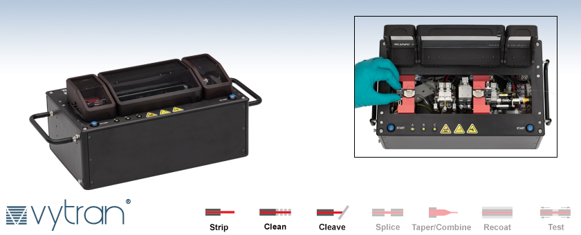
An operator adds a second clip to the station while a first fiber is being cleaned. The three covers are open to show the full interior.
Automatic Fiber Preparation Station


Please Wait
processing workflow, and demonstrates the stripping, cleaning, and cleaving stages.
Contact Us for Your Custom Fiber Processing Needs

Robert Walz
General Manager
Thorlabs Vytran® Division
My team is dedicated to creating fiber processing and inspection solutions that are suitable for your application. Existing products can be modified for different fiber types and sizes, form factors, or performance requirements. We also have experience integrating multiple process types into custom-designed instruments for particular production environments.
I look forward to discussing how our team can assist you in meeting the requirements for your application.

Features
- Automated Stripping, Cleaning, and Cleaving of Fibers in One Unit
- Simultaneous Processing of Two Fibers with Cladding from Ø80 µm to Ø125 µm
- User-Configurable to Process Two Different Fibers Simultaneously
- Typical Process Time of 75 s for Two Fibers
- Compact Dimensions: 335 mm x 205 mm x 120 mm (13.2" x 8.1" x 4.7")
- Configured at Time of Build for Clips Compatible with Thorlabs or Third-Party Splicers
- Cleaning Solvent and Waste are Contained within the Unit
This Automatic Fiber Preparation Station, which was designed to streamline the preparation of two fibers for high-quality splicing, is one example of our Custom Fiber Processing Capabilities. A customer came to us and communicated the need for high throughput without needing highly skilled operators, which led us to prioritize short processing times and low splice failure rates as design parameters. The final product is a fully automated unit that is capable of stripping, cleaning, and cleaving two fibers in parallel, thereby eliminating any manual handling between the different stages of preparation.
The station uses our proven thermo-mechanical stripping process to achieve high-quality splicing, increasing the splice yield and reliability following preparation. Furthermore, since the fibers do not need to be manually transferred between stations, the typical total processing time is reduced to 75 s. These yield improvements and time savings can significantly increase throughput in a production environment.
The fully integrated solution shown here accepts two single mode fibers with Ø125 µm cladding, cut approximately to desired length, and held in clips appropriate for the fusion splicer that will be employed following fiber preparation. The station is user-configurable to process different combinations of cladding diameters (Ø80 µm - Ø125 µm) and fiber types (single mode, multimode, or polarization-maintaining), including configurations for processing two different fibers in parallel.
The stripping, cleaning, and cleaving functionality is contained in an enclosure with L x W x H dimensions of 335 mm x 205 mm x 120 mm (13.2" x 8.1" x 4.7"), significantly reducing the amount of bench space occupied when compared to separate units to perform these steps. Three transparent lids enable clear visibility during the process and allow clips to be added or removed while one fiber is still being processed.
The station requires connection to compressed air and power supplies. An external power supply is included, but a source of compressed air must be supplied by the user. See the Specs tab for details about the compressed air supply requirements.
As different splicers have different geometries and accept different fiber clips, the preparation station is calibrated for the intended fusion splicer at time of build; it is not intended for frequent changes between significantly different splicers. For inquiries about customization options, we invite you to contact us.
Click to Enlarge
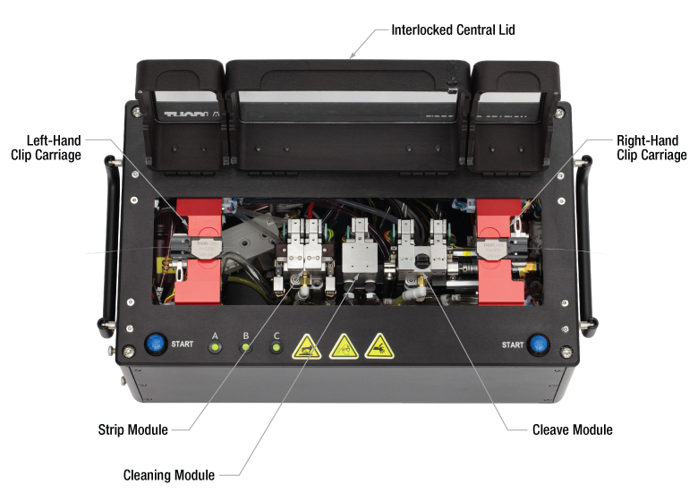
The features of the preparation station are noted in this image. Two clip carriages move the fiber clips among the strip, cleaning, and cleave modules in succession. The station features three transparent lids, with the central lid interlocked so that the station is not accidentally operated while unprotected.
Click to Enlarge
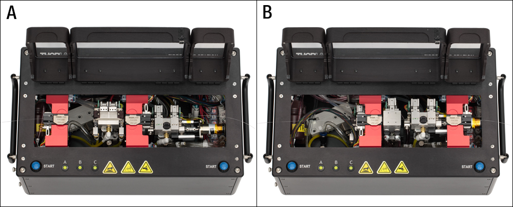
The automatic fiber preparation station is shown at two stages of the fiber process. The covers are open for demonstration purposes.
A: The fiber on the right is being stripped while the fiber on the left waits to start.
B: The fiber on the right is cleaved while the fiber on the left is cleaned.
Click to Enlarge
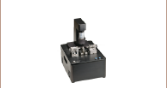
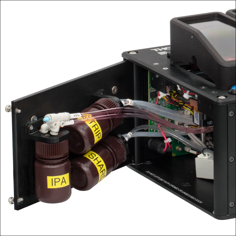
Opening the panel on the left side of the station allows the unit to be serviced by accessing bottles holding solvent, cleaning debris, and cleave shards.
| Automatic Fiber Preparation Station Specifications | |
|---|---|
| Operation | |
| Fiber Length | 27 mm - 43 mm |
| Fiber Buffer Diametera | ≤250 µm |
| Fiber Cladding Diametera | 80 µm - 125 µm |
| Fiber Type | Single Mode, Multimode, Polarization Maintaining |
| Nominal Air Pressure | 0.5 MPa (72.5 psi) |
| Operating Air Pressure Range | 0.48 MPa - 0.69 MPa (70 psi - 100 psi) |
| Peak Air Consumption | 30 L/min. (1.06 ft3/min.) |
| Process Time (Two Fibers) | 75 s (Typical) |
| Strip Module | |
| Strip Shoulder Positionb | 5 mm - 17 mm |
| Strip Blade Temperature | 40 °C (Idle), 70 °C (Max) |
| Cleaning Module | |
| Cleaning Solvent | Isopropyl Alcohol |
| Cleaning Times | 1 s - 10 s per Section |
| Cleave Module | |
| Cleave Length | 6 mm - 18 mm |
| Cleave Type | Flat Cleave |
| Cleave Angle Tolerance | ±0.5° |
| Cleave Method | Tension and Scribe |
| Tension | Programmable, 230 g Max |
| Scribec | Diamond Blade, Stepper Motor Controlled, 5000 Uses per Position, Nine Positions |
| Loading | Linear Tension, Stepper Motor Controlled |
| Electrical | |
| Power | 12 VDC |
| External Power Supply | 110 VAC - 240 VAC |
| Control Interface | Terminal Program via USB or Handset Controller |
| Interface | USB Y-Cable |
| General | |
| Dimensions (L x W x H) | 335 mm x 205 mm x 120 mm (13.2" x 8.1" x 4.7") |
| Weight | 7.3 kg (16.1 lbs) |
| Operating Temperature | 0 to 40 °C (Non-Condensing) |
| Storage Temperature | -20 to 70 °C |
| Posted Comments: | |
| No Comments Posted |