LBO Crystals for Second and Third Harmonic Generation
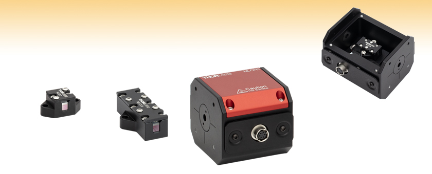
- Nonlinear Crystals for Type-I and Non-Critical Phase Matching Second Harmonic Generation and Type-II Sum Frequency Generation
- Crystal Lengths from 10 to 30 mm
- Drop-In Compatibility with Nonlinear Crystal Ovens
- Designed for Use with 1030 or 1064 nm Picosecond and Nanosecond Lasers
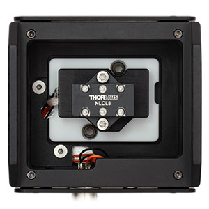
An NLCL8 non-critical phase matching crystal is mounted in an NLCH2 oven to maintain its temperature for phase matching.
NLCL1
Mounted LBO Crystal, Type-I SHG, 1064/532 nm, 10 mm Length
NLCL9
Mounted LBO Crystal, NCPM SHG, 1064/532 nm, 30 mm Length
NLCH1
Oven for Nonlinear Crystals up to 15 mm Long

Please Wait
| Key Common Specificationsa | |
|---|---|
| Material | Lithium Triborate (LiB3O5) |
| Crystal Face Dimensions | 3.0 mm x 3.0 mm |
| Clear Aperture | >80% of Crystal Face Area |
| Transmitted Wavefront Error | λ/3 @ 632.8 nm Over Clear Aperture |
| Surface Quality | 20-10 Scratch-Dig |
| Optic Axis Angleb Tolerance | <0.5° |
Click to Enlarge
Figure 1.1 An NLCL8 non-critical phase matching crystal is shown mounted in an NLCH2 nonlinear crystal oven for temperature control.
Features
- LBO (LiB3O5) Crystals Optimized for Second Harmonic (SHG) and Sum Frequency (SFG) Generation
- Type-I SHG: 1030 nm Fundamental / 515 nm SHG or 1064 nm Fundamental / 532 nm SHG
- Non-Critical Phase Matched (NCPM) SHG: 1064 nm Fundamental / 532 nm SHG
- Type-II SFG: 1064 nm Fundamental + 532 nm SHG / 355 nm Third Harmonic
- Appropriate for >0.5 ps pulses
- Mounted in Customized Holder to Protect Crystal Surfaces
- Ovens for Nonlinear Crystals Available for Temperature Control (Sold Below)
Thorlabs' Lithium Triborate (LBO) Second Harmonic Generation (SHG) and Sum Frequency Generation (SFG) Crystals for Picosecond and Nanosecond Pulsed Lasers are temperature-tunable to provide efficient SHG and SFG. SHG is a nonlinear process through which two photons with the same wavelength, called the fundamental, are converted into a single SHG photon with half the fundamental wavelength. SFG is a nonlinear process through which two photons with different wavelengths are converted into a single SFG photon with frequency equal to the sum of the frequencies of the two input photons. These uniaxial nonlinear crystals are appropriate for use with nanosecond, picosecond microchip, Nd:YAG, Nd:YLF, and Yb:YAG laser systems.
Pulse parameter information, including recommended minimum pulse durations and focal spot sizes, is provided in the Guidelines tab. Each crystal has an antireflective (AR) coating to provide low reflectance over its fundamental and second harmonic wavelength ranges, as well as the fundamental and sum frequency generated wavelength ranges for Item #s NLCL6 and NLCL7. To support pulsed laser applications, the crystals are offered with a range of length options from 10.00 mm to 30.00 mm that are matched to typical pulse durations and spot sizes, listed in the tables below. When there is not a perfect match between the available crystal length options and an application's laser pulse parameters, we recommend using a crystal whose length is shorter, rather than longer, than optimal. See the Specs tab for complete specifications for the nonlinear crystals listed below.
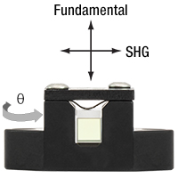
The crystals are each mounted in housings that are 21.0 mm wide and 10.8 mm tall, with varying lengths depending on the length of the crystal, and a clear aperture through the crystal of 2.7 mm x 2.7 mm. For type-I and NCPM SHG operation, the incident light at the fundamental wavelength should be vertically polarized and the SHG light should be horizontally polarized, as shown in Figure 1.2. For type-II SFG, the 355 nm light will have the same polarization direction as the fundamental. Under phase matched conditions, the efficiency of the SHG and SFG processes are improved, enabling the intensity of the SHG and SFG light to increase exponentially with propagation distance through the crystal. Phase matching in combination with suitable excitation intensities (>50 MW/cm2) typically provides >10% conversion efficiencies for these crystals.
To separate the second and third harmonics from the fundamental in the output from the crystal, we recommend using a harmonic beamsplitter, as seen in the schematics in the SHG and SFG Experimental Setups tab.
Click to Enlarge
Figure 1.2 The polarization axes for our mounted LBO nonlinear crystals are shown above a photo of the NLCL1 crystal. For the NLCL6 and NLCL7 SFG crystals, the orientation of the 355 nm output will be orthogonal to the 532 nm SHG.
Alignment for Optimal SHG
To optimize the SHG process in LBO, type-I and type-II phase matching can be achieved by aligning the polarization of the fundamental input light parallel to one of the crystal's principal ordinary axes, and then adjusting the angle between the optic axis and propagation direction, marked θ in Figure 1.2, so that both the fundamental and second harmonic light experience the same index of refraction (see the SHG Tutorial tab for a description of this process). For each of the type-I and type-II crystals below, the angle between the optic axis and the normal to the crystal surface, θ, was chosen so that phase matching would be optimized for normally incident light at the fundamental wavelength listed in the tables below. There will generally still be some small angular adjustment required for optimal phase matching. For information on how the optimal angle for phase matching can be tuned for different fundamental wavelengths, see the Guidelines tab.
 Click to Enlarge
Click Here for Raw Data
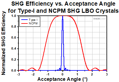
Figure 1.3 Type-I nonlinear crystals need to be carefully aligned; deviation of the incident beam angle by a fraction of a degree will substantially decrease the SHG efficiency. NCPM crystals are able to better maintain their efficiency despite slight angular deviation, avoiding tedious angle tuning.
Due to the substantial length of these crystals, temperature plays a significant role in the SHG and SFG efficiency and the alignment. We offer ovens (sold below) that are designed for simple drop-in compatibility with these mounted LBO crystals (see Figure 1.1) in order to hold the temperature of the crystals constant for consistent and efficient harmonic conversion. Our NCPM crystals (Item #s NLCL8 and NLCL9) are optimized for SHG at 150 °C and therefore require an oven for use; for more information on the temperature dependence of phase matching, please see the SHG Tutorial tab. The rest of our LBO crystals are designed to be used at room temperature, but will have inconsistent SHG and SFG efficiency if the temperature is not held stable. Our ovens can also be used to provide stability for the room temperature crystals; please see the Guidelines tab for more information on the temperature dependence of all of our LBO crystals.
Non-Critical Phase Matching
Non-critical phase matching (NCPM) is the method by which the SHG is tuned in our NLCL8 and NLCL9 NCPM LBO crystals and refers to the case where crystals are cut such that the fundamental and SHG polarizations are parallel to the principal axes. To achieve phase matching, the temperature of the crystal is used to tune the phase velocity of the two principal axes, rather than tuning the optic axis angle as is done in type-I and type-II phase matching. A consequence of reducing the dependence of phase matching to just the principal axes is to greatly increase the angular acceptance (or conversely decrease the angular sensitivity) of the phase matching process, as shown in Figure 1.3. This makes optically aligning these crystals straightforward and allows for independent tuning via crystal temperature. Another benefit of both the fundamental and SHG light propagating along the principal axes is the elimination of Poynting vector walk-off through the crystal. For more information on the benefits of NCPM, please see the SHG Tutorial tab.
Usage, Handling, and Care
When handling the crystals, use care and always wear gloves. These crystals scratch easily, and the material is hygroscopic. Protect the crystals from excess moisture such as high humidity environments. If needed, we recommend gently puffing with clean dry air only, as detailed in the Blowing Off the Surface of an Optic section in our Optics Handling and Care Tutorial.
| General Specifications | |||||||||
|---|---|---|---|---|---|---|---|---|---|
| Item # | NLCL4 | NLCL5 | NLCL1 | NLCL2 | NLCL3 | NLCL8 | NLCL9 | NLCL6 | NLCL7 |
| Application | Type-I SHG | Type-I SHG | Non-Critical Phase Matched SHG | Type-II SFG | |||||
| Fundamental Wavelength (1ω) | 1030 nm | 1064 nm | 1064 nm | - | |||||
| SHG Wavelength (2ω) | 515 nm | 532 nm | 532 nm | - | |||||
| SFG Wavelength (1ω + 2ω = 3ω) | - | - | - | 1064 nm + 532 nm : 355 nm | |||||
| Crystal Length | 10.00 mm | 20.00 mm | 10.00 mm | 15.00 mm | 20.00 mm | 20.00 mm | 30.00 mm | 10.00 mm | 15.00 mm |
| Crystal Length Tolerance | ±0.05 mm | ±0.05 mm | ±0.05 mm | ±0.05 mm | |||||
| Angle of Optic Axis (θ, Φ)a | 90°, 13.6° | 90°, 11.4° | 90°, 0° | 42.4°, 90° | |||||
| Optic Axis Angle (θ, Φ)a Tolerance | <0.5° | <0.5° | <0.5° | <0.5° | |||||
| AR Coating (AOI = 0°) |
R < 0.25% at 1030 nm and 515 nm | R < 0.25% at 1064 nm and 532 nm | R < 0.25% at 1064 nm and 532 nm | R < 0.5% at 1064 nm, 532 nm, and 355 nm |
|||||
| AR Coating Curveb | Raw Data |
Raw Data |
Raw Data |
Raw Data |
|||||
| Laser Induced Damage Thresholdc | >25 J/cm2 (1064 nm, 10 ns, 100 Hz, Ø220 μm) | >25 J/cm2 (1064 nm, 10 ns, 100 Hz, Ø220 μm) | >25 J/cm2 (1064 nm, 10 ns, 100 Hz, Ø220 μm) | >5 J/cm2 (532 nm, 5.5 ns, 100 Hz, Ø220 μm) | |||||
| Crystal Face Dimensions |
3.0 mm x 3.0 mm | ||||||||
| Crystal Face Dimensional Tolerance | ±0.1 mm | ||||||||
| Clear Aperture | >80% of Crystal Face Area | ||||||||
| Surface Quality | 20-10 Scratch-Dig | ||||||||
| Transmitted Wavefront Error | λ/3 @ 632.8 nm Over Clear Aperture | ||||||||
| Physical and Optical Properties | |
|---|---|
| Material | Lithium Triborate (LiB3O5) |
| Crystal Structure | Negative Biaxial, Orthorhombic mm2 |
| Transparency Range | 160 - 2600 nm |
| Second-Order Nonlinear Coefficientsa | d31 = 0.85 pm/V d32 = -0.67 pm/V d33 = 0.04 pm/V |
| Nonlinear Refractive Index (Kerr Index)b | 2.6 x 10⁻²⁰ m2/W @ 780 nm |
| Sellmeier Coefficientsc |  |
 |
|
 |
|
| Temperature Dependent Changes in the Indexc | |
| Thermal Conductivityd | kx = 2.7 W / m ⋅ K ky = 3.1 W / m ⋅ K kz = 4.5 W / m ⋅ K |
| Mohs Hardness | 6 Mohs |
| Density | 2.474 g/cm3 |
The values in this table are guidelines for optimal performance of the nonlinear crystals.
| Implementation Guidelines | |||||||||
|---|---|---|---|---|---|---|---|---|---|
| Item # | NLCL4 | NLCL5 | NLCL1 | NLCL2 | NLCL3 | NLCL8 | NLCL9 | NLCL6 | NLCL7 |
| Application | Type-I SHG | Type-I SHG | Non-Critical Phase Matched SHG | Type-II SFG | |||||
| Fundamental Wavelength (1ω) | 1030 nm | 1064 nm | 1064 nm | - | |||||
| SHG Wavelength (2ω) | 515 nm | 532 nm | 532 nm | - | |||||
| SFG Wavelength (1ω + 2ω = 3ω) | - | - | - | 1064 nm + 532 nm : 355 nm | |||||
| Recommended Operating Temperature | <60 °C | <60 °C | 150 °C | <60 °C | |||||
| Temperature Stabilitya | ±2.6 °C | ±1.4 °C | ±2.6 °C | ±1.8 °C | ±1.4 °C | ±1.0 °C | ±0.8 °C | ±1.4 °C | ±1.0 °C |
| SHG Efficiency vs. Temperatureb,c | Raw Data |
Raw Data |
Raw Data |
Raw Data |
|||||
| AOI vs. Temperatureb,c | Raw Data |
Raw Data |
- | Raw Data |
|||||
| AOI vs. Wavelengthb,d | Raw Data |
Raw Data |
- | Raw Data |
|||||
| Temperature vs. Wavelengthb,c,d | - | - | Raw Data |
- | |||||
| Minimum Recommended Focal Spot Size (1/e2 Diameter)e | 200 µmf | 400 µmf | 175 µmf | 260 µmf | 350 µmf | 69 µmg | 85 µmg | 221 µmf,h | 330 µmf,h |
| Circularity vs. Fundamental Mode Field Diameter (MFD)b,e | Raw Data |
Raw Data |
Raw Data |
- | |||||
| Minimum Recommended Pulse Duration (FWHM)e | 0.50 ps | 1.00 ps | 0.42 ps | 0.65 ps | 0.88 ps | 0.88 ps | 1.30 ps | 2.05 ps | 3.10 ps |
| Phase Matching Bandwidth (FWHM)e | 3.0 nm | 1.5 nm | 3.8 nm | 2.5 nm | 1.9 nm | 1.9 nm | 1.3 nm | 0.8 nm | 0.5 nm |
Second Harmonic Generation Experimental Setup

Figure 4.1 A schematic is shown of a setup used to frequency double the 1064 nm output of a QSL106B picosecond laser by passing through an NLCL8 noncritcal phase matching crystal mounted in an NLCH2 nonlinear crystal oven held at 150 °C. We recommend mounting the oven on a PY005(/M) 5-axis stage for full alignment control. The beam is collimated and focused to the optimal MFD in the crystal using the LA1509-B-ML and LA1484-B-ML lenses, respectively, and is linearly polarized using the WPQ10ME-1064 quarter- and WPH10ME-1064 half-wave plates. Output SHG light is reflected by the UBS24 dichroic beamsplitter while the fundamental wavelength passes through to a beam block. Remaining traces of the fundamental wavelength are then filtered out of the reflected beam via an FESH0800 shortpass filter.
Sum Frequency Generation Experimental Setup

Figure 4.2 A schematic is shown of a setup used to generate 355 nm sum frequency light from the 1064 nm output of a QSL106B picosecond laser by passing through an NLCL8 non-critcal phase matching crystal mounted in an NLCH2 nonlinear crystal oven held at 150 °C and an NLCL6 type-II SFG crystal in an NLCH1 nonlinear crystal oven held at 20 °C. We recommend mounting each oven on a PY005(/M) 5-axis stage for full alignment control. The beam is collimated and focused to the optimal MFD in between the crystals using the LA1509-B-ML and LA1484-B-ML lenses, respectively, and is linearly polarized using the WPQ10ME-1064 quarter- and WPH10ME-1064 half-wave plates. The 532 nm SHG light generated by the first crystal is incident on the second crystal along with the 1064 nm fundamental light, which together produce the sum frequency 355 nm light. The 355 nm light is reflected by the HBSY13 dichroic beamsplitter while the fundamental and SHG wavelengths pass through to a beam stop. Remaining traces of the fundamental and SHG wavelengths are then filtered out of the reflected beam via a second HBSY13 beamsplitter before the filtered sum frequency generated light is detected by the S401C optical power sensor.
Second Harmonic and Sum Frequency Generation and Phase Matching
Optimizing the intensity and beam quality of the second harmonic and sum frequency light provided by our nonlinear crystals requires choosing the crystal length appropriate to the duration of the input laser pulses, determining a focal spot size that balances the positive and negative effects of the focal region, and optimizing the phase matching conditions. Succinct guidance on each of these topics is provided by the graphs available on the Guidelines tab. Additional information and background, which can be helpful for interpreting the graphed data as well as more effectively using the crystals to generate second harmonic and sum frequency light, is included in the expandable sections below. Second harmonic generation (SHG) is a subset of sum frequency generation (SFG); this tutorial focuses on the specific case of SHG but will touch on SFG and the relevant distinctions.
Click on a question to expand the corresponding passage that provides an answer, and then click again to contract the section. Answers to questions lower in the list reference the discussions in preceding sections.
What is nonlinear optics?
Click to Enlarge
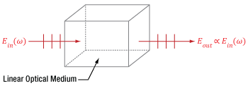
Figure 5.1 A beam of light accumulates phase and is attenuated as it propagates through a linear medium, but the photons of the beam do not interact with each other. Due to this, the input (Ein) and output (Eout) electric fields have the same frequency (ω) and are directly proportional.
Click to Enlarge
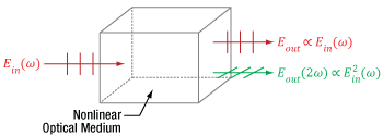
Figure 5.2 This nonlinear optical medium supports second harmonic generation and the input light is the same as in Figure 5.1. In addition to providing fundamental-frequency electric fields, as in Figure 5.1, the light output from this nonlinear medium also includes frequency doubled light, whose electric field Eout(2ω) is proportional to the square of the total input electric field.
Nonlinear optics refers to different optical phenomena that can occur when light alters the properties of the surrounding material. These phenomena are called nonlinear optics because the strength of the material's response is proportional to the square, cube, or other higher power of the light's total electric field. Since the light usually must be intense to produce a measurable nonlinear response, laser light is often used to generate desired nonlinear effects.
A material's nonlinear response occurs in addition to the linear response, which is proportional to only the first power of the light's electric field. The interaction between the light and the material is completely conventional (linear) when optical and material conditions are not appropriate for generating nonlinear phenomena. In such cases, light waves in a material propagate together without affecting one another, whether or not they are part of the same beam or pulse.
An example of a material's linear response to light is illustrated in Figure 5.1, in which an input beam is described by its electric field amplitude (Ein), frequency (ω), and polarization orientation (vertical). The beam accumulates phase and experiences conventional losses from effects like reflection and material absorption before it is output, but otherwise the beam is unaffected. The total electric field (Eout) output by the material has an amplitude that is directly proportional to the that of the input beam. In addition, the input and output light has the same frequency and polarization direction.
Nonlinear processes occur when the presence of the light in the material creates conditions in which different light waves can interact with one another. In some cases, light waves from the same beam or pulse interact, and in other cases light waves with significantly different frequencies and / or polarizations interact. Nonlinear phenomena include the generation of new frequencies of light, lensing of laser light propagating in uniform materials, and modulation effects. In the case of frequency generation, the light output by the nonlinear material will include a frequency of light different than any of the input beams' frequencies.
An example of nonlinear frequency generation is illustrated in Figure 5.2, in which the light is incident on a nonlinear optical material. While the incident light is the same as in Figure 5.1, the material supports second harmonic generation, and the electric field output from this crystal includes a new color, which has double the frequency of the input beams. The amplitude of this frequency-doubled light is proportional to the square of the total input electric field, and the losses accumulated by the two fundamental-frequency beams include the photons converted into frequency-doubled light.
What is second harmonic generation (SHG)?
Click to Enlarge
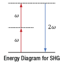
Figure 5.3 This energy diagram shows the input photons on the left and the generated photons on the right. In the case of ideal second harmonic generation the frequency (ω) of the input photons is exactly twice that of the output photon.
Click to Enlarge
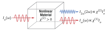
Figure 5.4 This nonlinear optical medium supports second harmonic generation and the input light is the same as in Figure 5.1. In addition to providing fundamental-frequency electric fields, as in Figure 5.1, the light output from this nonlinear medium also includes frequency doubled light, whose electric field Eout(2ω) is proportional to the square of the total input electric field. The efficiency of the SHG process is proportional to the square of the of the input light intensity multiplied by a material parameter χ(2).
Second harmonic generation (SHG) is a nonlinear optical process that effectively combines pairs of nominally similar photons into a single photon. This nonlinear process occurs due to interactions between the light and the surrounding material. When the input photons are identical, their frequencies are exactly equal, and this frequency (ω) is called the fundamental frequency. The frequency (2ω) of the generated photon is exactly double the fundamental. In other words, the output light wave's frequency is the second harmonic of the input wave's frequency. This relationship gives SHG its name.
While this seems to suggest the two input photons must have the same frequency, this is not the case. Photons in a beam or pulse of light have frequency values that span a non-zero spectral range around the fundamental frequency. It is possible to combine two photons with frequencies that are different, but within this spectral range. When this occurs, the nonlinear process is typically still called SHG, and the output photons are still described as being frequency doubled. This is also true for input photons from broad-bandwidth femtosecond pulses. However, to simplify the following discussion of SHG, it will be assumed that all input photons have the same fundamental frequency.
Every photon has an energy that is proportional to its frequency. Energy diagrams, like the one shown in Figure 5.3, typically take advantage of this property to relate the frequencies of photons input to and output by nonlinear optical processes. Each arrow represents the energy of a single photon and is labeled using the photon's frequency. Arrows pointing up correspond to input photons, and arrows pointing down correspond to generated photons. The dotted horizontal lines are typically called virtual energy levels and are not related to energy levels in the material.
The energy diagram illustrates the remarkable fact that nonlinear processes like second harmonic generation are lossless, so that the material does not gain or lose energy as a result of the process. The material provides the specific environment required for the process to occur, and there is interaction between the material and the photons, but no photons are absorbed or emitted by the material during the process. This is the reason the sum of the input photons' energies exactly equals the sum of the output photon's energy.
Not all of the input photons will undergo second harmonic generation as the light propagates through the material. As illustrated in Figure 5.4, the efficiency of the second harmonic generation process is proportional to the square of the of the input light intensity multiplied by a material specific parameter (χ(2), which is pronounced "kai two"). Values of χ(2) are usually extremely small (on the order of 10-13 m/V), and large input intensities (Io) are typically required for second harmonic generation to be efficient. As the input light intensity increases, the intensity of the frequency doubled (I2ω) light increases relative to the fundamental-frequency output light (Iω).
SHG is a Specific Case of Sum-Frequency Generation
Sum-frequency generation (SFG) is a nonlinear optical process during which input photons are combined into output photons. There are no restrictions on the maximum frequency difference between the input photons. Usually, the term SFG is reserved for cases in which the input photons do not come from the same light source, and / or when the spectra of the input beams or pulses do not overlap.
Second harmonic generation is a specific case of SFG. The nonlinear optical process is typically described as SHG when both photons originate from the same beam or pulse, and the term is especially preferred when frequency doubling the input light. Since SHG combines input photons that have nominally the same energy, second harmonic generation is a degenerate case of SFG.
Can all crystals be used for SHG?
Only optical materials which have a non-zero χ(2) parameter support SHG, and not all crystals fulfill this requirement. An example of a crystal that can be used for SHG is β-BBO. A material is crystalline when its atoms, ions, or molecules are arranged in a repeating pattern. If there is no central point around which the crystal pattern is symmetric (i.e. if the crystal is not centrosymmetric), the crystal has a non-zero χ(2) parameter and can be used for SHG.
Click to Enlarge
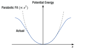
Figure 5.6 When light's oscillating electric field interacts with a centrosymmetric material, an electron's induced potential energy, which is illustrated as a function of the electron's displacement (x) from its equilibrium position, is symmetric and described by a polynomial function consisting of even powers of x.
Click to Enlarge
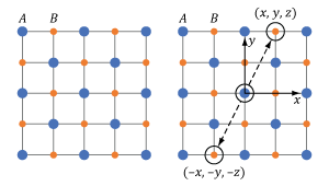
Figure 5.5 This cubic crystal structure includes two different ions, A and B, in a repeating pattern. The crystal structure is centrosymmetric since the crystal at point (x, y, z) and its inverse (-x, -y, -z) are identical.
Click to Enlarge
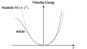
Figure 5.8 When light's oscillating electric field interacts with a non-centrosymmetric material, an electron's induced potential energy, which is illustrated as a function of the electron's displacement (x) from its equilibrium position, is asymmetric for larger displacements. This curve is described by a polynomial function consisting of even and odd powers of x.
Click to Enlarge
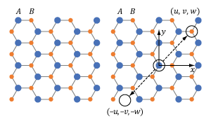
Figure 5.7 This wurtzite crystal structure includes two different ions, A and B, in a repeating pattern. The crystal structure is not centrosymmetric since there is at least one point (u, v, w) which is not identical to its inverse (-u, -v, -w).
Centrosymmetric Crystal
The repeating crystalline pattern of one type of centrosymmetric crystal is illustrated in Figure 5.5. As is true for all centrosymmetric crystals, the structure at point (x, y, z) is identical to the structure at the inverse location (-x, -y, -z). Due to the crystal's structural symmetry, the material's response is the same whether the incident light's electric field vector points in one direction or in the opposite direction.
The material’s response to light occurs due to interactions between the light’s oscillating electric field and the electrons in the material. An electron bound to an atom in the material experiences forces contributed by the atom and the light’s electric field, as well as the surrounding atoms in the material. The blue curve in Figure 5.6 was calculated using the Lorentz model of an atom, which takes these forces into account using a classical mechanics approach. This model can also be used to estimate the χ(2) parameter.
In Figure 5.6, the X-axis corresponds to the position of the electron, which is in equilibrium at x = 0. The input light’s oscillating electric field moves the electron back-and-forth between positive and negative displacements. The greater the intensity of the electric field, the larger the displacement of the electron. The central and surrounding atoms exert a restoring force on the displaced electron, returning it to equilibrium. This restoring force provides the electron with potential energy, which is plotted on the Y-axis and increases as the electron moves further from equilibrium.
At moderate displacements, the central atom exerts the majority of the restoring force, and the electron’s corresponding potential energy is symmetric and approximately parabolic (the dashed gray curve is a parabolic fit). At larger displacements, achieved using higher-intensity light, surrounding atoms contribute more to the restoring force, as well as the electron’s potential energy. At these larger displacements, the electron’s potential energy deviates from parabolic but remains symmetric.
The symmetric material response is a consequence of the centrosymmetric structure of the crystal. In order to support SHG, this curve would have to be asymmetric. Mathematically, a non-zero χ(2) parameter requires the polynomial describing the curve to include odd powers of x, while the polynomial describing the curve in Figure 5.6 includes only even powers of x.
Non-Centrosymmetric Crystal
An example of a non-centrosymmetric material is shown in Figure 5.7. In the case of these materials, there is aways at least one location (u, v, w) for which the crystal structure differs from the crystal structure at the inverse location (-u, -v, -w).
The potential energy of an electron, as a function of its displacement from its equilibrium position, has been calculated for a non-centrosymmetric material using the Lorentz model of the atom (Figure 5.8). When the incident light has low intensity, the displacement of the electron from its equilibrium position is small, and the majority of the restoring force is provided by the central atom. Within this limited region, the electron's corresponding potential energy function is symmetric and approximately parabolic, which indicates a linear optical material response. When illuminated by higher-intensity light, the electron's displacement is greater and the surrounding atoms contribute more to the restoring force. Since the distribution of the surrounding atoms is not symmetric, neither is the restoring force nor the potential energy well confining the electron for these higher displacements.
The polynomial needed to model this asymmetric curve includes even, as well as odd, powers of x. It is the non-zero cubic (x3) terms in this polynomial that provide a non-zero χ(2) parameter. A third-order polynomial term is required for the generation of the second-order nonlinearities quantified by the χ(2) parameter, since the x3 term is the lowest-order correction to the linear optics model. Because the asymmetric response only becomes significant for larger electron displacements, high-intensity light is required to induce SHG.
Uniaxial Crystal
A secondary requirement for efficient production of second harmonic light, which will be discussed in a section below, is the so-called phase matching condition. At a high level, phase matching is matching of the phase velocities between the input fundamental frequency with the second harmonic frequency. This is frequently accomplished by utilizing the birefringence of anisotropic optical materials.
Uniaxial crystals are a specific type of anisotropic material, where two of the three principal refractive indices are the same. The name “uniaxial” is derived from there being a single propagation axis in these crystals, known as the optical axis or c-axis, on which the index of refraction is the same for all polarization orientations. Many common optical materials belong to the uniaxial class: calcite, quartz, sapphire, and β-BBO.
Reference:
Robert W. Boyd, Nonlinear Optics (Academic Press, New York, 1992) pp. 17 - 52.
Can a crystal's refractive index depend on the light's polarization orientation within the crystal?
Certain materials have a refractive index that depends on the orientation of the light's electric field polarization. An example is birefringent materials, which include uniaxial crystals like β-BBO. Uniaxial crystals characteristically have two principal refractive indices, which are called the ordinary (no) and extraordinary (ne) refractive indices. The principal refractive indices are the maximum and minimum the material can provide. Since light’s electric field (E) is always polarized perpendicular to the propagation direction (k), both the propagation direction and polarization state must be known to determine the refractive indices experienced by the light's polarization components.
A Cartesian coordinate system, with the Z-axis aligned along the crystal’s optic axis (c), can be used to relate the light's polarization components (Ex, Ey, and Ez) to a birefringent crystal's geometry.
In uniaxial crystals, the refractive index can be determined by referencing the angles of the propagation direction and polarization orientation relative to the crystal's optic axis (c).
Since the crystal is uniaxial, the refractive index for fields polarized orthogonal to the crystal's optic axis is no. For fields parallel to the crystal's optic axis, the refractive index is ne. The two components (Ex and Ey) of light polarized orthogonal to the crystal's optic axis have refractive indices equal to no, since the crystal is uniaxial. Light polarized parallel (Ez) to the crystal’s optic axis has a refractive index equal to ne.
It is also possible for birefringent materials to provide a refractive index value between no and ne, which is discussed in a following section.
Click to Enlarge
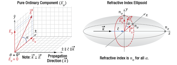
Figure 5.9 The diagram on the left indicates the propagation direction (k) of the incident light is along the optic axis (c) of the crystal. The incident light can be decomposed into orthogonal polarization components Ex and Ey. The diagram on the right is a refractive index ellipsoid, with a conic section (red circle) at the XY-plane. This constant-radius circle shows the refractive index is always no in this case and the crystal does not affect the light's polarization.
Light Propagating Parallel to the Optic Axis
(Example: Optical Windows)
Light propagating along the optic axis (Z-axis) of a birefringent material always has a refractive index equal to no. This is a defining trait of the optic axis.
The left side of Figure 5.9 illustrates the electric field components of light propagating along the crystal's optic axis. These polarization state components can include Ex and Ey, but not Ez. In other words, the electric field vector is orthogonal to the Z-axis, so the angle φ equals 90°. The relative magnitude of Ex and Ey depends on angle α.
The right side of Figure 5.9 uses an ellipsoidal volume, the so-called index ellipsoid, to map all possible refractive indices provided by the material for all combinations of light propagation directions and polarization orientations. In the case of this material, the maximum possible refractive index is ne and the minimum is no. The opposite can be true for other materials. The red circle drawn on the ellipsoid is a conic section that marks the refractive indices that light propagating along the optic axis will experience. The refractive index of both Ex and Ey components equals no. Due to this, E has a refractive index of no, regardless of the orientation of the E vector in the XY-plane. Therefore, the Ex and Ey components travel with the same phase velocity, and the polarization state stays the same as the light propagates.
Optical windows made from uniaxial crystals, such as sapphire (for example Item # WG31050), are typically cut or polished so that normally incident light propagates parallel to the optic axis. This is done so that the window has no effect on the polarization state of the transmitted light, as described above. When the end faces are orthogonal to the optic axis like this, the crystal is often described as Z-cut or C-cut.
Click to Enlarge
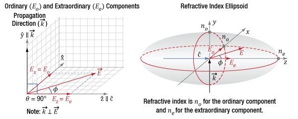
Figure 5.10 The diagram on the left indicates the incident light's propagation direction (k) and polarization state orientation (E), which can be decomposed into orthogonal components Ex and Ez. The propagation direction is aligned to the Y-axis and is orthogonal (θ = 90°) to the optic axis (c) of the crystal. The diagram on the right is a refractive index ellipsoid, with conic sections (red ellipses) drawn in the XZ- and XY-planes. The refractive index (ne) of the extraordinary component (Ee = Ez) is indicated by the intersection of the Z-axis and ellipse, while the refractive index (no) of the ordinary component (Eo = Ex) is indicated by the intersection of the X-axis and the ellipse. The angle φ determines the two components' relative magnitudes.
Click to Enlarge
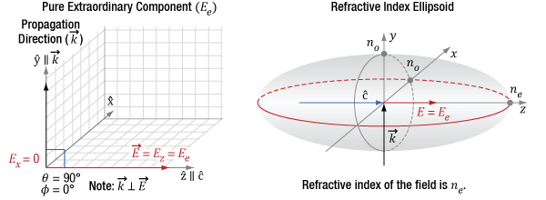
Figure 5.11 The diagram on the left indicates the incident light's propagation direction (k), which is aligned to the Y-axis, which is orthogonal (θ = 90°) to the optic axis (c) of the crystal. Since φ is 0°, the only polarization component is Ez, which is also the extraordinary component. The diagram on the right indicates this component has a refractive index of ne.
Click to Enlarge
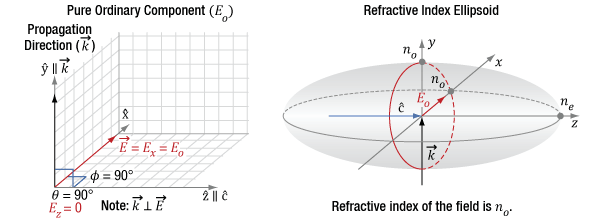
Figure 5.12 The diagram on the left indicates the incident light's propagation direction (k), which is aligned to the Y-axis, which is orthogonal (θ = 90°) to the optic axis (c) of the crystal. Since φ is 90°, the only polarization component is Ex, which is also the ordinary component. The figure on the right indicates this component has a refractive index of no.
Light Propagating Perpendicular to the Optic Axis
(Example: Wave Plate)
When linearly polarized light incident on a birefringent material propagates in a direction orthogonal to the optic axis (θ = 90°), the light may have components polarized both parallel and perpendicular to the optic axis (Z-axis). This is illustrated in Figure 5.10, in which the light’s propagation direction is aligned to the Y-axis for convenience. The refractive index of the electric field component parallel to the optic axis (Ez) is ne, and the component perpendicular to the optic axis (Ex) is no. This is the largest refractive index difference that can exist between two polarization components in the material.
The vertical, red circle on the right side of Figure 5.10 is the conic section of the index ellipsoid in a plane perpendicular to the k-vector. The horizontal, red elliptical conic section indicates a difference between the refractive indices of the orthogonal principal polarization axes of  and
and  .
.
Due to different refractive indices, the two polarization components travel at different velocities as they propagate through the material. This causes a phase shift between the two polarization states Ez and Ex.
Wave plates are often fabricated from uniaxial birefringent materials, with the optic polished and mounted so that normally incident light propagates orthogonal to the optic axis. Markings on the wave plate housing, such as the ones on Item # WPQ05M-266, or flat features on the perimeter of the optic, identify the orientations of the ordinary and extraordinary axes, or for a typical waveplate made of crystal quartz the so-called fast and slow axes, respectively.
Light polarized parallel to the fast axis travels with a faster velocity in the material due to the lower refractive index, compared with light polarized parallel to the slow axis. Quartz, a commonly used waveplate material, is a positively uniaxial crystal with a smaller ordinary refractive index compared to its extraordinary index. For quartz, the fast axis is the ordinary axis.
Tuning a wave plate requires rotating the optic in the XZ-plane, around the Y-axis, so that the light's propagation direction is maintained perpendicular to the optic axis. This rotation changes the angle φ, while keeping θ = 90°.
When the angle φ is between 0° and 90°, the linear polarization state has both orthogonal Ex and Ez components, and the wave plate will delay one component relative to the other. However, note that since θ is unchanged, there is no change in the indices of refraction of the two principal orthogonal polarization orientations along  and
and  .
.
When φ = 0°, as illustrated in Figure 5.11, the light's polarization state is oriented along the optic axis. This provides an extraordinary component (Ez = Ee) without an ordinary component. This component has a refractive index equal to ne. Since there is only one polarization component, the wave plate does not affect the polarization state.
The polarization state is similarly unaffected when the linear polarization state is aligned with the X-axis (φ = 90°), as seen in Figure 5.12. In this case, there is an ordinary component (Ex = Eo) without an extraordinary component and the refractive index is no.
Click to Enlarge
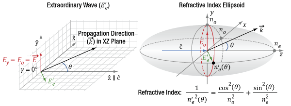
Figure 5.13 In the diagram on the left, the propagation direction (k) of the incident light and the optic axis (c) of the uniaxial birefringent crystal are in the same plane (XZ plane). The angle (θ) between k and c is arbitrary. The input fundamental field, represented by the red vector, is parallel to the Y-axis. The SHG light is polarized perpendicularly, represented by the green vector in the XZ plane. Rather than decompose the SHG polarization into components Ex and Ez, the light is typically described as an extraordinary wave (E'e) with a refractive index, n'e. In the diagram on the right, n'e, which depends on θ, is indicated by the intersection of the conic section illustrated by the red ellipse with the XZ plane.
Click to Enlarge
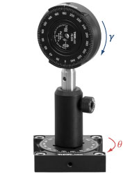
Figure 5.15 How θ and γ are defined in a laboratory setup.
Click to Enlarge
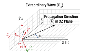
Figure 5.14 In the diagram above, the propagation direction (k) of the incident light and the optic axis (c) of the uniaxial birefringent crystal are in the same plane (XZ-plane). The angle (θ) between k and c is arbitrary. In this case, the incident fundamental field (E), represented by the red vector, is rotated off of the laboratory reference frame by an angle γ, and thus only a portion of the fundamental (Eoγ) is converted by SHG into the resulting polarization E'e, represented by the green vector.
Light Propagating at an Arbitrary Angle
(Example: Nonlinear Crystals)
In uniaxial crystals, the field polarizations are arranged as in Figure 5.13 for type-I second harmonic generation (SHG). The k-vector is at an angle θ from the optic axis,  , and in the XZ plane. The input fundamental electric field (Eo) is polarized parallel to one of the principal ordinary axes, in this case the Y-axis, and has a refractive index of no. The index of refraction for light polarized in the ordinary direction, parallel to
  , is independent of changes to θ.
The SHG light is polarized in the XZ plane and is orthogonal to both the Eo and the k-vector. Rather than decompose the polarization of the SHG light into Ex and Ez components, the electric field is typically described as an extraordinary wave (E'e). The refractive index for this extraordinary wave, n'e, changes as a function of θ. n'e(θ) can be calculated using the equation in Figure 5.13. The ellipse defining the extraordinary index of refraction as a function of θ is a conic section of the index ellipsoid. The two extreme cases are 1) θ = 0°, where the field is polarized along the other principal ordinary axis,  , and the index of refraction is no, or 2), θ = 90°, where the field is polarized along the principal extraordinary axis,
  , and the index of refraction is ne. The prime (') notation is used to denote index of refraction for cases in between the two extreme cases of θ.
Figure 5.14 shows a departure from an ideal polarization orientation for type-I SHG, where the incident fundamental field has a linear polarization but is rotated by a degree γ from the principal ordinary axis  . The fundamental field now driving the type-I SHG process is the Eoγ component of the incident field. At γ = 90°, there would be zero SHG output, since the drive field Eoγ = 0.
In practice, γ is nonzero when the polarization states of light in a laboratory reference frame are not matched to the intrinsic principal axes in the crystal frame. To orient the two reference frames together, e.g. the vertically polarized light from the laser on the optical table is parallel to  in the crystal, we mount the nonlinear crystal in a rotation stage to finely adjust γ to zero, first by eye using the markings on the housing and then further, if necessary, using the SHG output power as feedback. Figure 5.15 shows the orientation of γ in a laboratory frame rotation of the crystal. In this example case, the nonlinear crystal is mounted in an RSP1 rotation mount on top of an RP01 rotation stage. Changes in γ and θ adjust the orientation of the optic axis,
  . In this case, adjustments in γ have been used to align
  with the horizontal plane and one of the principle ordinary axes vertically. For a vertically polarized input beam, this orientation allows the rotation stage to be used to adjust θ.
Why is phase matching (angle tuning) necessary for SHG?
Click to Enlarge
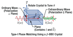
Figure 5.17 Type-I phase matching can be used with a negative uniaxial crystal like β-BBO. This requires the fundamental frequency (ω) to be polarized perpendicular to the plane that includes the light's propagation vector (k) and the crystal's optic axis (c). The second harmonic light is then polarized parallel to the plane. Angle tuning adjusts θ and is performed by rotating the crystal around the y axis.
Click to Enlarge
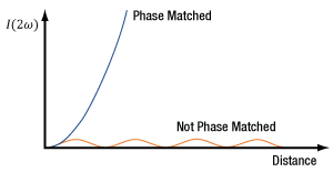
Figure 5.16 Without phase matching the intensity of the generated second harmonic light, I(2ω), remains below a low threshold. This intensity can increase exponentially when phase matching is performed.
Click to Enlarge
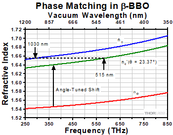
Figure 5.19 The refractive index (ne') of the extraordinary wave can be varied between ne and no by tuning the angle (θ) between the crystal's optic axis and the propagation direction of the input ordinary wave. At an angle of 23.37°, fundamental light at 1030 nm is phase matched with SHG light at 515 nm.
Click to Enlarge
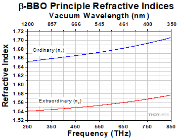
Figure 5.18 The ordinary and extraordinary refractive indices of β-BBO vary with frequency and wavelength due to a material property called dispersion. Dispersion exists in all media except vacuum.
| Table 5.20 Refractive Index Orientations | ||
|---|---|---|
| Wave Type | Angle | Refractive Index |
| Ordinary | k ⊥  |
no |
| Extraordinary | θ = 0° | no |
| 0° < θ < 90° | ne'(θ ) | |
| θ = 90° | ne | |
 Click to Enlarge
Click Here for Raw Data
Figure 5.21 Type-I nonlinear crystals need to be carefully aligned; deviation of the incident beam angle by a fraction of a degree will substantially decrease the SHG efficiency. NCPM crystals however are able to better maintain their efficiency despite slight angular deviation, avoiding tedious angle tuning.
Phase matching significantly improves the conversion efficiency and can be required to obtain sufficient frequency-doubled light for applications, but second harmonic generation (SHG) will occur even if phase matching is not performed. The effect of phase matching on the output intensity of SHG light (I2ω) is illustrated in Figure 5.16. When phase matching is not performed, the intensity of the SHG light alternately increases and decreases, but generally remains at a low level. In contrast, the intensity of phase-matched SHG light can increase exponentially with propagation distance through the material. Phase matching is performed by appropriately orienting the input fundamental frequency (ω) light with respect to the SHG crystal (Figure 5.17).
With ideal phase matching, the fundamental (ω) and second harmonic (2ω) frequencies travel at the same phase velocity, so that all of the second harmonic light created along the beam path adds constructively. The phase velocity is the rate at which the field carrier, i.e. the sine wave, travels in a material. The rate at which a pulse envelope travels in a material is called the group velocity and defines the speed of the energy packet comprising the optical pulse traveling through the material.
The two frequencies' phase velocities are equal when they have the same refractive index. The refractive indices for these two frequencies are generally not equal, because all media except vacuum are dispersive. This means that a material's refractive index depends on the light's frequency. As an example, β-BBO's principal ordinary and extraordinary refractive indices are graphed, in Figure 5.18, over a frequency range that extends from the visible into the IR. Over this range, the refractive index increases for higher frequencies.
Several different phase-matching approaches can be used to equalize the refractive indices of the fundamental and second harmonic light. Among these are type-0, -I, and -II critical phase matching as well as non-critical phase matching (NCPM).
Type-0 Phase Matching
While we currently do not offer any type-0 phase matching nonlinear crystals, it is a helpful illustration to understand phase matching for SHG. In type-0 critical phase matching, two photons of the fundamental frequency (ω) with extraordinary polarization (parallel to the optical axis) relative to the crystal combine to form one SHG photon with double the frequency (2ω) and extraordinary polarization. This is referred to as the ee-e arrangement, since both the input photons and the SHG photon are polarization-oriented in the extraordinary plane. Type-0 phase matching is often used in combination with quasi-phase matching in periodically poled materials.
Type-I Phase Matching
Type-I critical phase matching uses linearly polarized light and the difference between the ordinary and extraordinary refractive indices. This is a common approach for negative uniaxial crystals in which no > ne. The fundamental-frequency input beam and the generated second-harmonic-frequency output beam orientations for type-I phase matching are illustrated in Figure 5.17. This is the so-called oo-e arrangement, as the two fundamental photons are polarization-oriented along the ordinary axis and the second harmonic photon's polarization is in the extraordinary plane. Notably, for type-I phase matching, the refractive index is the same at the fundamental and second harmonic wavelengths.
The linearly polarized fundamental-frequency wave is aligned to the crystal so that it is polarized along the ordinary refractive index axis (y axis), which is perpendicular to the plane that includes both the light's propagation vector (k) and the crystal's optic axis (c). The second harmonic frequency wave is generated as an extraordinary wave, which is polarized orthogonal to the fundamental-frequency ordinary wave.
Rotating the crystal around the y axis tunes the angle (θ) between the propagation vector and the crystal's optic axis. This varies the extraordinary wave's refractive index (n'e(θ)) between the values of ne and no, as illustrated in Figure 5.19. The red curve corresponds to n'e(90°) = ne, while the blue curve plots the values for no. The position of the green curve depends on θ. In this case, the angle θ has been tuned to provide a refractive index for 515 nm light that matches the refractive index for 1030 nm light. This tuning angle is therefore optimized for type-I SHG phase matching and a fundamental-frequency input beam of 1030 nm.
Some manufacturers' SHG crystals, including Thorlabs', provide near-phase-matched conditions for normally incident input light for a specified fundamental frequency. These manufacturers polish the faces of the SHG crystals such that the angle between the normally incident light and the optic axis is the phase-matched angle for the specified frequency. The phase matching angle can be adjusted by rotating the crystal around the y axis. An adjustment that is typically within a few degrees can either optimize the performance of the crystal in the setup or match another fundamental frequency in the crystal's operating range.
Type-II Phase Matching
In type-II critical phase matching, the index of refraction at the fundamental and SHG frequencies are not equal; two photons of the fundamental frequency (ω) with orthogonal polarizations (one ordinary and one extraordinary) combine to form one SHG photon with double the frequency (2ω) and ordinary polarization. This is the so-called oe-o arrangement, as the two input photons have orthogonal polarizations and the resultant photon's polarization is in the ordinary plane. Similarly to type-I, rotating type-II crystals around the y axis tunes the angle (θ) between the propagation vector and the crystal's optic axis. This varies the extraordinary wave's refractive index (n'e(θ)) between the values of ne and no.
Our type-II crystals (Item #s NLCL6 and NLCL7) are actually designed for sum-frequency generation (SFG), not SHG. A fundamental frequency ordinary photon at 1064 nm combined with an extraordinary SHG photon at 532 nm (such as one produced by one of our 1064 nm type-I SHG crystals) produces an ordinary photon with 355 nm wavelength, which is the third harmonic of 1064 nm. These wavelengths correspond to input photons at the fundamental frequency of 281.8 THz and second harmonic frequency of 563.5 THz in a vacuum adding to generate the sum-frequency photon at 845.3 THz, which corresponds to the 355 nm resultant wavelength.
Non-Critical Phase Matching
Non-critical phase matching, which refers to the case where crystals are cut such that the fundamental and SHG polarizations are parallel to principal axes, is the method by which the SHG is tuned in our NLCL8 and NLCL9 NCPM LBO crystals. To achieve phase matching, the temperature of the crystal is used to tune the phase velocity of the two principal axes, rather than tuning the optic axis angle as is done in type-I and type-II phase matching. Reducing the dependence of phase matching to just the principal axes greatly increases the angular acceptance (or conversely decreases the angular sensitivity) of the phase matching process, as shown in Figure 5.21. This makes optical alignment of these crystals straightforward and allows for independent tuning via crystal temperature. Another benefit of aligning the polarizations of both the fundamental and SHG light parallel to the principle axes is the elimination of Poynting vector walk-off through the crystal. The details of temperature dependence in nonlinear crystals will be discussed further in a section below.
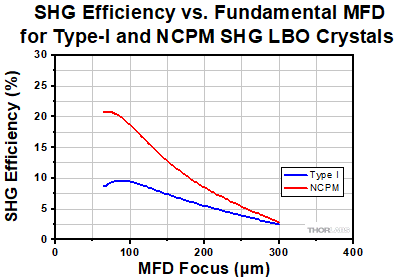
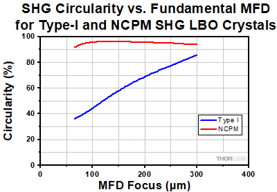
In addition to simplifying alignment for optimal efficiency, the low angular sensitivity of NCPM has the benefit of maintaining beam circularity and SHG efficiency at smaller mode field diameters (MFD), corresponding to higher intensities, when compared to type-I SHG crystals. This is demonstrated in Figures 5.22 and 5.23, where the circularity and SHG efficiency of a type-I and an NCPM crystal are plotted as a function of MFD focus size. At an MFD of 300 µm the two crystals have comparable performance, but as the MFD is condensed to under 100 µm, the integrity of the SHG of type-I crystals quickly deteriorates. This allows for the conversion of substantially more SHG photons than with type-I and type-II crystals since the pump laser can be focused to a smaller spot, resulting in higher intensity, without losing circularity.
 Click to Enlarge
Click Here for Raw Data
Figure 5.23 At large focal spot sizes, type-I and NPCM nonlinear crystals have similar efficiency, but with the higher intensities at smaller mode field diameters, NCPM outperforms type-I for SHG efficiency.
 Click to Enlarge
Click Here for Raw Data
Figure 5.22 At large focal spot sizes, type-I and NPCM nonlinear crystals both produce relatively circular beams, but with the higher intensities at smaller mode field diameters, the circularity from type-I crystals deteriorates significantly while that of NCPM crystals remains high.
Why is short pulse duration a concern for SHG?
When choosing an SHG crystal, the pulse duration of the laser source must be taken into consideration. A mismatch between the duration and crystal length will lead to SHG pulses longer in time and narrower in spectral content than possible under ideal conditions.
The issue that arises when using ultrashort pulses for second harmonic generation (SHG) is that shorter pulses have larger bandwidths, but the ideal phase-matched condition can be achieved for only a single fundamental wavelength at a time. Due to this, the quality of the phase match can be significantly worse towards the spectral edges of broad-bandwidth pulses. A second concern is that the group velocity mismatch between the second harmonic and fundamental-frequency pulses will result in one pulse lagging the other as the two propagate. This is called temporal walk-off and will occur even under optimal phase-matched conditions.
Both broad-bandwidth pulses and temporal walk-off cause a reduction in the conversion efficiency, as well as worsen the optical quality of the second harmonic pulses. The appropriate crystal length should be chosen to minimize both effects.
Click to Enlarge
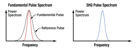
Figure 5.24 On the left, the fundamental input pulse (red) has a spectral width narrower than the reference pulse spectral width (dotted black line). Therefore, the second harmonic pulse spectrum, shown on the right, has a spectral width approximately the same as the ideal case. Ideally, every frequency in the fundamental pulse spectrum would be simultaneously phase matched.
Click to Enlarge
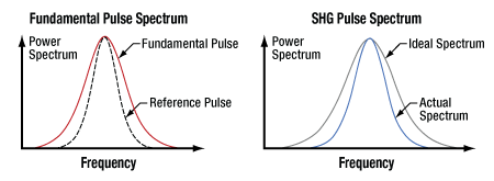
Figure 5.25 On the left, the fundamental input pulse (red) has a spectral width wider than the reference pulse spectral width (dotted black line). Therefore, the second harmonic pulse spectrum (blue), shown on the right, has a spectral width smaller than in the ideal case. Ideally, every frequency in the fundamental pulse spectrum would be simultaneously phase matched.
Phase Matching Bandwidth Limitations
As discussed in another section, Is phase matching (angle tuning) necessary for SHG?, the angle between the light's propagation direction and the crystal's optic axis can be tuned so that the refractive index of a particular frequency (ω) in the fundamental input pulse exactly equals the refractive index of twice the input frequency (2ω). It is typical to optimize phase matching conditions for the frequency at approximately the center of the pulse's bandwidth. Since the refractive index does not vary linearly with frequency in dispersive crystals like β-BBO, it is not possible to optimally phase match every frequency in the input pulse's spectral range with the corresponding second harmonic frequency in the generated pulse.
Assuming a crystal of a given length, it is possible to define a reference pulse with a spectral range that is the maximum that can be adequately phase matched. This spectral bandwidth limitation can also be thought of in terms of an SHG spectral filter whose passband depends on both the specific crystal and the pulse's center frequency. Frequencies outside of this filter’s passband will be rejected from undergoing the SHG process.
When an input pulse's spectral range is equal to or narrower than the reference pulse, the generated second harmonic pulse has a duration that is shorter by a factor of 1/√2 and a spectral width that is broader by a factor of √2. Physically, when the fundamental spectrum is well within the reference pulse spectrum, the SHG pulse intensity profile is the square of the fundamental intensity profile, effectively truncating the duration. This case is illustrated in Figure 5.24.
When the input pulse has a spectral range that exceeds the width of the reference pulse (Figure 5.25), the second harmonic pulse spectrum (blue curve) is narrower than it would be if all frequencies in the input pulse were phase matched (gray curve). The spectrally narrowed SHG pulse spectrum is said to be apodized, since an effect of the fundamental pulse exceeding the maximum input bandwidth limit is the removal of the highest and lowest frequencies from the SHG pulse spectrum.
The length of the SHG crystal significantly affects the spectral width of the reference pulse, or alternatively the bandwidth of the SHG filter. As illustrated in Table 5.26, the shorter the crystal, the wider the reference pulse spectrum. This table assumes a fundamental center wavelength in the near-IR.
| Table 5.26 Crystal Lengths | |
|---|---|
| β-BBO Crystal Length | Pulse Durationa |
| Less than One Millimeter | Less than 100 Femtoseconds |
| Several Millimeters | Hundreds of Femtoseconds |
| Tens of Millimeters | Picoseconds |
Temporal Walk-Off
There are two velocities that define the propagation of light in optical media: the phase and group velocities. The phase velocity is the speed of the carrier, the oscillation of the electric field, and the velocity that is matched between the fundamental and second harmonic frequencies for phase matching. The phase velocity relative to the speed of light in a vacuum is defined by the index of refraction.
Click to Enlarge
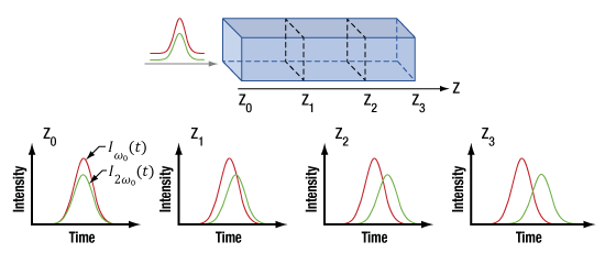
Figure 5.27 The diagram at the top shows two pulses with different center frequencies incident on a material. The group velocity delay between the pulses when they enter the material is zero. The four lower figures illustrate that the group velocity delay (temporal walk-off) increases as the pulses propagate through the material. The temporal walk-off is illustrated for distances Z0 through Z3, which are indicated on the diagram at top.
The group velocity is the speed of the pulse, or more formally the envelope of the electric field. The group index similarly governs the speed of the envelope relative to the speed of light in a vacuum and is dependent on the dispersion of the material. The group velocity and the phase velocity are not equal, meaning the sine wave of the carrier and the envelope of the pulse move through optical media at different speeds.
The group velocities of the fundamental and second harmonic pulses are also different, even when phase-matched, and the magnitude of the group velocity mismatch depends on the crystal properties and the optical frequencies in the pulses. In some cases, the mismatch can be small. For example, when a β-BBO crystal is used to frequency double 1550 nm light and provide 775 nm light, the group velocity mismatch is only a few femtoseconds per millimeter.
However, in many cases, the difference in the fundamental and second harmonic pulse velocities can cause one pulse to significantly lag the other. The temporal walk-off of the slower pulse with respect to the faster can be a substantial fraction of the pulse duration. This is illustrated in Figure 5.27.
The temporal walk-off is often considered severe when the temporal lag exceeds the duration of the fundamental pulse. Severe walk-off can result in temporal lag that irreparably increases the duration of the output second harmonic pulse. Since the dynamics of this process are highly subject to experimental parameters, it is difficult to arbitrarily predict the precise effects on the second harmonic pulse. These effects can include back conversion, in which second harmonic light is converted back to fundamental light, and spectral narrowing of the SHG pulse.
Choosing Crystal Length
The length of the crystal is an important parameter to consider when optimizing the SHG process for the parameters of particular input pulses. Absent phase-matching and temporal walk-off effects, the SHG output increases exponentially with crystal length. The goal when picking an SHG crystal is to balance the crystal length with the limitations determined by the fundamental pulse. Decreasing the crystal length reduces effects related to both phase-matching bandwidth limitations and temporal walk-off, which are directly related. For example, consider a fundamental pulse propagating over a given crystal length. When the temporal walk-off is greater than the duration of the fundamental pulse, this pulse will also have a spectral bandwidth that greatly exceeds the spectral width of the reference pulse. A general rule for limiting the detrimental effects related to both physical effects is to choose a crystal length that limits the fundamental and second harmonic temporal walk-off to no more than the duration of the fundamental pulse.
Why is focal spot size important to consider?
It is typically necessary to focus the incident light in the crystal for SHG applications, since efficient generation of second harmonic light requires high peak intensities, such as 109 W/cm2. When using femtosecond pulses with moderate energies in the nanojoule range, obtaining the required peak intensities can require small focal spots. A recommended guideline for focusing femtosecond laser pulses into a nonlinear crystal is to maintain a Rayleigh range that is at least several times longer than the length of the SHG crystal. This minimizes the chance of damaging the crystal, as well as reduces the negative effects of spatial phase mismatch and spatial (Poynting vector) walk-off.
| Table 5.28 Tiberius Pulse Parameters | ||
|---|---|---|
| Wavelength |  |
800 nm |
| FWHM Duration | T | 140 fs |
| Energy | E | 30 nJ |
| β-BBO Crystal | ||
| Thickness | d | 0.6 mm |
| Focused Pulse Parameters | ||
| Mode Field Diametera | MFD | 13.5 µm |
| Effective Areab | 7.16 x 10⁻⁷ cm2 | |
| Peak Power |  |
201 kW |
| Peak Irradiancec | 281 GW/cm2 | |
Click to Enlarge
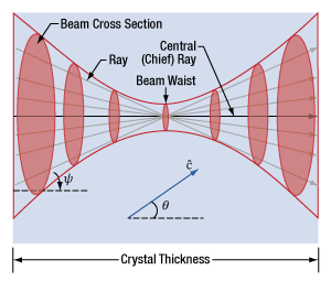
Figure 5.29 This diagram illustrates a beam's focal region in a uniaxial birefringent material. Straight lines, representing rays, are drawn through the center of the beam waist. As the beam diverges from the beam waist, the energy in the beam is distributed over a larger cross sectional area. The crystal axis is c. The chief ray is parallel to the direction used to measure the tuning angle (θ), which is optimized during phase matching. Conversion efficiency is optimized for rays parallel to the chief ray and worse for rays at larger angles (ψ) to the chief ray.
Rayleigh Length vs. Crystal Thickness
When laser light is focused to a spot, the diameter of the beam waist is the focal spot size, and the rate at which the light diverges from the beam waist is related to the Rayleigh range (zR). The Rayleigh range quantifies the distance, measured from the beam waist, over which the beam diameter is approximately constant. The shorter the Rayleigh range, the larger the rate of divergence.
When the Rayleigh range is less than the crystal thickness, the distance over which the beam is optimally intense is less than the crystal thickness. The efficiency of the SHG process decreases substantially as the fundamental beam diverges from its focus, since the pulse energy is distributed across a larger beam cross section.
For femtosecond pulses the phase-matching/temporal walk-off limitations will set the crystal length to be relatively short (sub-mm to a few-mm). As will be discussed below, there is a focusing numerical aperture (NA) limitation to the SHG phase-matching process exactly analogous to the spectral phase matching limitation discussed in the previous section (Why is short pulse duration a concern for SHG? Phase Matching Bandwidth Limitations). This spatial focusing constraint on the SHG process will generally result in the crystal length always being less than the Rayleigh range of the input focused pulse.
Crystal Damage
There is the danger of exceeding the laser-induced damage threshold (LIDT) when ultrafast pulses are focused to small spot sizes. As an example, consider femtosecond pulses from Thorlabs' Tiberius laser (see Table 5.28). Selecting the crystal thickness based on the pulse duration to balance maximum length with phase-matching/temporal walk-off limitations, the 0.6 mm crystal would be recommended for the 140 fs pulse at 800 nm. If the focal spot were chosen such that the 2zR = Crystal Length, then the focal spot size would be 13.5 μm. Using the equations provided in Table 5.28, the 30 nJ input Gaussian pulse is estimated to provide the notably high peak intensity (irradiance) of 281 GW/cm2 on the crystal's input face.
Spatial Phase Matching
The type-I phase matching process relies on matching the ordinary and extraordinary indices of refraction for the fundamental and second-harmonic frequencies, which is achieved through precise orientation of the crystal optic axis and input propagation vector. A focused laser pulse, or beam, has angular content, formally called spatial frequencies, to produce the small focal spot. We use Numerical Aperture (NA) to describe the extent of this angular content. Ideally, the fundamental laser light would be collimated throughout the crystal, since collimated light resembles a group of rays aligned to the same direction with an NA of zero.
From a ray-model perspective, the propagation direction defines the orientation of the central (chief) ray in Figure 5.29. The SHG process is affected by the range of angles over which incident light propagates, because light that is not parallel to the chief ray has reduced phase-matching relative to the chief ray. Instead of the reference pulse power spectrum comprising an apodization filter, in the spatial domain the filter would be in NA. The angular domain apodization filter however, is only in one-dimension defined by the plane k and  .
.
The angular content of a focused beam can be visualized by tracing rays from the lens to the focal spot. Each ray drawn from the lens to a tightly focused spot (Figure 5.29) makes a different angle (ψ) with the chief ray, and the range of angles increases with the NA. As the range of angles increases beyond the reference NA filter (or angular domain apodization filter width), the phase-matching of the rays outside of the filter width diminishes therefore reducing the SHG conversion efficiency of those rays. The angular content of the resultant SHG pulse, or beam, in the dimension of the angular filter is reduced from an ideal case. In the perpendicular dimension, the SHG beam preserves the angular content of the input beam, since there’s no angular filter in that dimension. A diverging beam with asymmetric NA’s, i.e. in the horizontal and vertical dimensions, leads to an elliptical beam.
Spatial (Poynting Vector) Walk-Off
As the second harmonic light propagates, its energy flows in a different direction than that of the fundamental light. The spatial walk-off angle depends on the size of the beam and the crystal length. While the angle can be significant, it is usually small, typically on the order of 10 mrad, and can be neglected.
In the case of type-I phase matching and β-BBO crystals, the fundamental light propagates as an extraordinary wave in the crystal, while the second harmonic light propagates as an ordinary wave. The energy in both waves propagates in directions determined by their Poynting vectors. Snell's law does not describe the direction of energy flow, but it can be used to calculate the direction of the k-vector in the crystal.
Why is temperature important?
Click to Enlarge
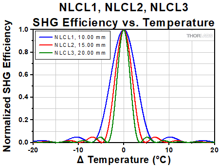
Figure 5.30 The temperature dependence of the NLCL1 10 mm long, NLCL2 15 mm long, and NLCL3 20 mm long nonlinear crystals is plotted above. Increased length leads to a sharper temperature dependence due to a longer path length in the crystal.
Temperature alters the refractive index of materials, and the longer the path through the material, the greater the impact of this altered refractive index on phase matching conditions. Under phase matched conditions, the efficiency of the SHG process is improved, enabling the intensity of the SHG and SFG light to increase exponentially with propagation distance through the crystal.
Our LBO SHG crystals are substantially longer than our β-BBO SHG crystals, so the temperature of the LBO crystals plays a significant role in the nonlinear process due to the increased phase matching sensitivity. This dependence is especially pronounced in non-critical phase matching (NCPM) crystals (Item #s NLCL8 and NLCL9), as these are typically longer. This is apparent in Figure 5.30 where the temperature dependence of the SHG efficiency of our NLCL1, NLCL2, and NLCL3 crystals is plotted; these crystals are identical aside from their lengths which vary from 10 mm (Item # NLCL1) to 20 mm (Item # NLCL3). A small change in temperature will drastically affect the efficiency of the 20 mm crystal while the 10 mm crystal will maintain its SHG integrity over a wider temperature range. Therefore, it is essential to keep constant control over the temperature of these thick LBO nonlinear crystals in order to reliably and efficiently convert fundamental light into second harmonic or sum frequency light.
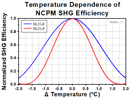
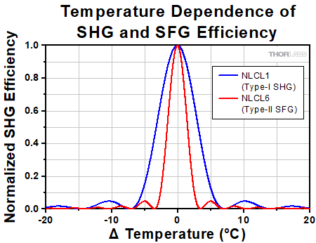
Figure 5.31 shows the change in efficiency of type-I SHG and type-II SFG with temperature for two 10 mm long critically phase matched LBO crystals. The different nonlinear processes have varying levels of dependence on temperature, but all of our type-I and type-II critically phase matched LBO crystals are designed to have peak efficiency at around zero degrees angle of incidence at a temperature of 20 °C; their second harmonic generation and sum frequency generation efficiencies are reduced by half when the temperature deviates from 20 °C by just two or three degrees. Figure 5.32 shows this temperature dependence for the NCPM crystals, Item #s NLCL8 and NLCL9, as a function of deviation from the phase matching temperature, with peak efficiency around 150 °C. The long crystal length and increased dependence of phase matching on temperature result in sensitivity curves with 1 °C deviations cutting the SHG efficiency in half, necessitating stable temperature control.
Click to Enlarge
Figure 5.32 The temperature dependence of SHG efficiency in our NCPM nonlinear crystals is plotted above. Deviation from the phase matching temperature by even one degree can drastically decrease the harmonic generation efficiency.
Click to Enlarge
Figure 5.31 The temperature dependence of SHG and SFG efficiency in 10 mm long type-I and type-II nonlinear crystals is plotted above. Deviation by a few degrees can drastically decrease the harmonic generation efficiency.
| Table 6.1 Damage Threshold Specificationsa | |
|---|---|
| Item # | Damage Threshold |
| NLCL4 | >25 J/cm2 (1064 nm, 10 ns, 100 Hz, Ø220 μm) |
| NLCL5 | |
| NLCL1 | |
| NLCL2 | |
| NLCL3 | |
| NLCL8 | |
| NLCL9 | |
| NLCL6 | >5 J/cm2 (532 nm, 5.5 ns, 100 Hz, Ø220 μm) |
| NLCL7 | |
Damage Threshold Data for Thorlabs' LBO Crystals
The specifications in Table 6.1 are measured data for Thorlabs' LBO Crystals for Second Harmonic and Sum Frequency Generation.
Laser Induced Damage Threshold Tutorial
The following is a general overview of how laser induced damage thresholds are measured and how the values may be utilized in determining the appropriateness of an optic for a given application. When choosing optics, it is important to understand the Laser Induced Damage Threshold (LIDT) of the optics being used. The LIDT for an optic greatly depends on the type of laser you are using. Continuous wave (CW) lasers typically cause damage from thermal effects (absorption either in the coating or in the substrate). Pulsed lasers, on the other hand, often strip electrons from the lattice structure of an optic before causing thermal damage. Note that the guideline presented here assumes room temperature operation and optics in new condition (i.e., within scratch-dig spec, surface free of contamination, etc.). Because dust or other particles on the surface of an optic can cause damage at lower thresholds, we recommend keeping surfaces clean and free of debris. For more information on cleaning optics, please see our Optics Cleaning tutorial.
Testing Method
Thorlabs' LIDT testing is done in compliance with ISO/DIS 11254 and ISO 21254 specifications.
First, a low-power/energy beam is directed to the optic under test. The optic is exposed in 10 locations to this laser beam for 30 seconds (CW) or for a number of pulses (pulse repetition frequency specified). After exposure, the optic is examined by a microscope (~100X magnification) for any visible damage. The number of locations that are damaged at a particular power/energy level is recorded. Next, the power/energy is either increased or decreased and the optic is exposed at 10 new locations. This process is repeated until damage is observed. The damage threshold is then assigned to be the highest power/energy that the optic can withstand without causing damage. A histogram such as that below represents the testing of one BB1-E02 mirror.
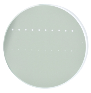
The photograph above is a protected aluminum-coated mirror after LIDT testing. In this particular test, it handled 0.43 J/cm2 (1064 nm, 10 ns pulse, 10 Hz, Ø1.000 mm) before damage.
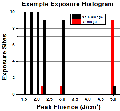
| Example Test Data | |||
|---|---|---|---|
| Fluence | # of Tested Locations | Locations with Damage | Locations Without Damage |
| 1.50 J/cm2 | 10 | 0 | 10 |
| 1.75 J/cm2 | 10 | 0 | 10 |
| 2.00 J/cm2 | 10 | 0 | 10 |
| 2.25 J/cm2 | 10 | 1 | 9 |
| 3.00 J/cm2 | 10 | 1 | 9 |
| 5.00 J/cm2 | 10 | 9 | 1 |
According to the test, the damage threshold of the mirror was 2.00 J/cm2 (532 nm, 10 ns pulse, 10 Hz, Ø0.803 mm). Please keep in mind that these tests are performed on clean optics, as dirt and contamination can significantly lower the damage threshold of a component. While the test results are only representative of one coating run, Thorlabs specifies damage threshold values that account for coating variances.
Continuous Wave and Long-Pulse Lasers
When an optic is damaged by a continuous wave (CW) laser, it is usually due to the melting of the surface as a result of absorbing the laser's energy or damage to the optical coating (antireflection) [1]. Pulsed lasers with pulse lengths longer than 1 µs can be treated as CW lasers for LIDT discussions.
When pulse lengths are between 1 ns and 1 µs, laser-induced damage can occur either because of absorption or a dielectric breakdown (therefore, a user must check both CW and pulsed LIDT). Absorption is either due to an intrinsic property of the optic or due to surface irregularities; thus LIDT values are only valid for optics meeting or exceeding the surface quality specifications given by a manufacturer. While many optics can handle high power CW lasers, cemented (e.g., achromatic doublets) or highly absorptive (e.g., ND filters) optics tend to have lower CW damage thresholds. These lower thresholds are due to absorption or scattering in the cement or metal coating.

LIDT in linear power density vs. pulse length and spot size. For long pulses to CW, linear power density becomes a constant with spot size. This graph was obtained from [1].
Pulsed lasers with high pulse repetition frequencies (PRF) may behave similarly to CW beams. Unfortunately, this is highly dependent on factors such as absorption and thermal diffusivity, so there is no reliable method for determining when a high PRF laser will damage an optic due to thermal effects. For beams with a high PRF both the average and peak powers must be compared to the equivalent CW power. Additionally, for highly transparent materials, there is little to no drop in the LIDT with increasing PRF.
In order to use the specified CW damage threshold of an optic, it is necessary to know the following:
- Wavelength of your laser
- Beam diameter of your beam (1/e2)
- Approximate intensity profile of your beam (e.g., Gaussian)
- Linear power density of your beam (total power divided by 1/e2 beam diameter)
Thorlabs expresses LIDT for CW lasers as a linear power density measured in W/cm. In this regime, the LIDT given as a linear power density can be applied to any beam diameter; one does not need to compute an adjusted LIDT to adjust for changes in spot size, as demonstrated by the graph to the right. Average linear power density can be calculated using the equation below.

The calculation above assumes a uniform beam intensity profile. You must now consider hotspots in the beam or other non-uniform intensity profiles and roughly calculate a maximum power density. For reference, a Gaussian beam typically has a maximum power density that is twice that of the uniform beam (see lower right).
Now compare the maximum power density to that which is specified as the LIDT for the optic. If the optic was tested at a wavelength other than your operating wavelength, the damage threshold must be scaled appropriately. A good rule of thumb is that the damage threshold has a linear relationship with wavelength such that as you move to shorter wavelengths, the damage threshold decreases (i.e., a LIDT of 10 W/cm at 1310 nm scales to 5 W/cm at 655 nm):

While this rule of thumb provides a general trend, it is not a quantitative analysis of LIDT vs wavelength. In CW applications, for instance, damage scales more strongly with absorption in the coating and substrate, which does not necessarily scale well with wavelength. While the above procedure provides a good rule of thumb for LIDT values, please contact Tech Support if your wavelength is different from the specified LIDT wavelength. If your power density is less than the adjusted LIDT of the optic, then the optic should work for your application.
Please note that we have a buffer built in between the specified damage thresholds online and the tests which we have done, which accommodates variation between batches. Upon request, we can provide individual test information and a testing certificate. The damage analysis will be carried out on a similar optic (customer's optic will not be damaged). Testing may result in additional costs or lead times. Contact Tech Support for more information.
Pulsed Lasers
As previously stated, pulsed lasers typically induce a different type of damage to the optic than CW lasers. Pulsed lasers often do not heat the optic enough to damage it; instead, pulsed lasers produce strong electric fields capable of inducing dielectric breakdown in the material. Unfortunately, it can be very difficult to compare the LIDT specification of an optic to your laser. There are multiple regimes in which a pulsed laser can damage an optic and this is based on the laser's pulse length. The highlighted columns in the table below outline the relevant pulse lengths for our specified LIDT values.
Pulses shorter than 10-9 s cannot be compared to our specified LIDT values with much reliability. In this ultra-short-pulse regime various mechanics, such as multiphoton-avalanche ionization, take over as the predominate damage mechanism [2]. In contrast, pulses between 10-7 s and 10-4 s may cause damage to an optic either because of dielectric breakdown or thermal effects. This means that both CW and pulsed damage thresholds must be compared to the laser beam to determine whether the optic is suitable for your application.
| Pulse Duration | t < 10-9 s | 10-9 < t < 10-7 s | 10-7 < t < 10-4 s | t > 10-4 s |
|---|---|---|---|---|
| Damage Mechanism | Avalanche Ionization | Dielectric Breakdown | Dielectric Breakdown or Thermal | Thermal |
| Relevant Damage Specification | No Comparison (See Above) | Pulsed | Pulsed and CW | CW |
When comparing an LIDT specified for a pulsed laser to your laser, it is essential to know the following:
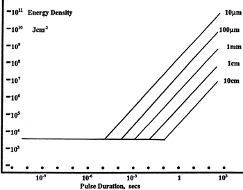
LIDT in energy density vs. pulse length and spot size. For short pulses, energy density becomes a constant with spot size. This graph was obtained from [1].
- Wavelength of your laser
- Energy density of your beam (total energy divided by 1/e2 area)
- Pulse length of your laser
- Pulse repetition frequency (prf) of your laser
- Beam diameter of your laser (1/e2 )
- Approximate intensity profile of your beam (e.g., Gaussian)
The energy density of your beam should be calculated in terms of J/cm2. The graph to the right shows why expressing the LIDT as an energy density provides the best metric for short pulse sources. In this regime, the LIDT given as an energy density can be applied to any beam diameter; one does not need to compute an adjusted LIDT to adjust for changes in spot size. This calculation assumes a uniform beam intensity profile. You must now adjust this energy density to account for hotspots or other nonuniform intensity profiles and roughly calculate a maximum energy density. For reference a Gaussian beam typically has a maximum energy density that is twice that of the 1/e2 beam.
Now compare the maximum energy density to that which is specified as the LIDT for the optic. If the optic was tested at a wavelength other than your operating wavelength, the damage threshold must be scaled appropriately [3]. A good rule of thumb is that the damage threshold has an inverse square root relationship with wavelength such that as you move to shorter wavelengths, the damage threshold decreases (i.e., a LIDT of 1 J/cm2 at 1064 nm scales to 0.7 J/cm2 at 532 nm):

You now have a wavelength-adjusted energy density, which you will use in the following step.
Beam diameter is also important to know when comparing damage thresholds. While the LIDT, when expressed in units of J/cm², scales independently of spot size; large beam sizes are more likely to illuminate a larger number of defects which can lead to greater variances in the LIDT [4]. For data presented here, a <1 mm beam size was used to measure the LIDT. For beams sizes greater than 5 mm, the LIDT (J/cm2) will not scale independently of beam diameter due to the larger size beam exposing more defects.
The pulse length must now be compensated for. The longer the pulse duration, the more energy the optic can handle. For pulse widths between 1 - 100 ns, an approximation is as follows:

Use this formula to calculate the Adjusted LIDT for an optic based on your pulse length. If your maximum energy density is less than this adjusted LIDT maximum energy density, then the optic should be suitable for your application. Keep in mind that this calculation is only used for pulses between 10-9 s and 10-7 s. For pulses between 10-7 s and 10-4 s, the CW LIDT must also be checked before deeming the optic appropriate for your application.
Please note that we have a buffer built in between the specified damage thresholds online and the tests which we have done, which accommodates variation between batches. Upon request, we can provide individual test information and a testing certificate. Contact Tech Support for more information.
[1] R. M. Wood, Optics and Laser Tech. 29, 517 (1998).
[2] Roger M. Wood, Laser-Induced Damage of Optical Materials (Institute of Physics Publishing, Philadelphia, PA, 2003).
[3] C. W. Carr et al., Phys. Rev. Lett. 91, 127402 (2003).
[4] N. Bloembergen, Appl. Opt. 12, 661 (1973).
In order to illustrate the process of determining whether a given laser system will damage an optic, a number of example calculations of laser induced damage threshold are given below. For assistance with performing similar calculations, we provide a spreadsheet calculator that can be downloaded by clicking the LIDT Calculator button. To use the calculator, enter the specified LIDT value of the optic under consideration and the relevant parameters of your laser system in the green boxes. The spreadsheet will then calculate a linear power density for CW and pulsed systems, as well as an energy density value for pulsed systems. These values are used to calculate adjusted, scaled LIDT values for the optics based on accepted scaling laws. This calculator assumes a Gaussian beam profile, so a correction factor must be introduced for other beam shapes (uniform, etc.). The LIDT scaling laws are determined from empirical relationships; their accuracy is not guaranteed. Remember that absorption by optics or coatings can significantly reduce LIDT in some spectral regions. These LIDT values are not valid for ultrashort pulses less than one nanosecond in duration.

Figure 71A A Gaussian beam profile has about twice the maximum intensity of a uniform beam profile.
CW Laser Example
Suppose that a CW laser system at 1319 nm produces a 0.5 W Gaussian beam that has a 1/e2 diameter of 10 mm. A naive calculation of the average linear power density of this beam would yield a value of 0.5 W/cm, given by the total power divided by the beam diameter:

However, the maximum power density of a Gaussian beam is about twice the maximum power density of a uniform beam, as shown in Figure 71A. Therefore, a more accurate determination of the maximum linear power density of the system is 1 W/cm.
An AC127-030-C achromatic doublet lens has a specified CW LIDT of 350 W/cm, as tested at 1550 nm. CW damage threshold values typically scale directly with the wavelength of the laser source, so this yields an adjusted LIDT value:

The adjusted LIDT value of 350 W/cm x (1319 nm / 1550 nm) = 298 W/cm is significantly higher than the calculated maximum linear power density of the laser system, so it would be safe to use this doublet lens for this application.
Pulsed Nanosecond Laser Example: Scaling for Different Pulse Durations
Suppose that a pulsed Nd:YAG laser system is frequency tripled to produce a 10 Hz output, consisting of 2 ns output pulses at 355 nm, each with 1 J of energy, in a Gaussian beam with a 1.9 cm beam diameter (1/e2). The average energy density of each pulse is found by dividing the pulse energy by the beam area:

As described above, the maximum energy density of a Gaussian beam is about twice the average energy density. So, the maximum energy density of this beam is ~0.7 J/cm2.
The energy density of the beam can be compared to the LIDT values of 1 J/cm2 and 3.5 J/cm2 for a BB1-E01 broadband dielectric mirror and an NB1-K08 Nd:YAG laser line mirror, respectively. Both of these LIDT values, while measured at 355 nm, were determined with a 10 ns pulsed laser at 10 Hz. Therefore, an adjustment must be applied for the shorter pulse duration of the system under consideration. As described on the previous tab, LIDT values in the nanosecond pulse regime scale with the square root of the laser pulse duration:

This adjustment factor results in LIDT values of 0.45 J/cm2 for the BB1-E01 broadband mirror and 1.6 J/cm2 for the Nd:YAG laser line mirror, which are to be compared with the 0.7 J/cm2 maximum energy density of the beam. While the broadband mirror would likely be damaged by the laser, the more specialized laser line mirror is appropriate for use with this system.
Pulsed Nanosecond Laser Example: Scaling for Different Wavelengths
Suppose that a pulsed laser system emits 10 ns pulses at 2.5 Hz, each with 100 mJ of energy at 1064 nm in a 16 mm diameter beam (1/e2) that must be attenuated with a neutral density filter. For a Gaussian output, these specifications result in a maximum energy density of 0.1 J/cm2. The damage threshold of an NDUV10A Ø25 mm, OD 1.0, reflective neutral density filter is 0.05 J/cm2 for 10 ns pulses at 355 nm, while the damage threshold of the similar NE10A absorptive filter is 10 J/cm2 for 10 ns pulses at 532 nm. As described on the previous tab, the LIDT value of an optic scales with the square root of the wavelength in the nanosecond pulse regime:

This scaling gives adjusted LIDT values of 0.08 J/cm2 for the reflective filter and 14 J/cm2 for the absorptive filter. In this case, the absorptive filter is the best choice in order to avoid optical damage.
Pulsed Microsecond Laser Example
Consider a laser system that produces 1 µs pulses, each containing 150 µJ of energy at a repetition rate of 50 kHz, resulting in a relatively high duty cycle of 5%. This system falls somewhere between the regimes of CW and pulsed laser induced damage, and could potentially damage an optic by mechanisms associated with either regime. As a result, both CW and pulsed LIDT values must be compared to the properties of the laser system to ensure safe operation.
If this relatively long-pulse laser emits a Gaussian 12.7 mm diameter beam (1/e2) at 980 nm, then the resulting output has a linear power density of 5.9 W/cm and an energy density of 1.2 x 10⁻⁴ J/cm2 per pulse. This can be compared to the LIDT values for a WPQ10E-980 polymer zero-order quarter-wave plate, which are 5 W/cm for CW radiation at 810 nm and 5 J/cm2 for a 10 ns pulse at 810 nm. As before, the CW LIDT of the optic scales linearly with the laser wavelength, resulting in an adjusted CW value of 6 W/cm at 980 nm. On the other hand, the pulsed LIDT scales with the square root of the laser wavelength and the square root of the pulse duration, resulting in an adjusted value of 55 J/cm2 for a 1 µs pulse at 980 nm. The pulsed LIDT of the optic is significantly greater than the energy density of the laser pulse, so individual pulses will not damage the wave plate. However, the large average linear power density of the laser system may cause thermal damage to the optic, much like a high-power CW beam.
Thorlabs offers a wide selection of optics optimized for use with femtosecond and picosecond laser pulses. Please see below for more information.
| Low-GDD Mirrors | |||||
|---|---|---|---|---|---|
 |
 |
 |
 |
 |
 |
| 355 - 445 nm | 460 - 590 nm | 700 - 930 nm | 970 - 1150 nm | 1400 - 1700 nm | 1760 - 2250 nm |
| Dielectric Mirror | High-Power Mirrors for Picosecond Lasers |
Metallic Mirrors | Low-GDD Pump-Through Mirrors |
||
|---|---|---|---|---|---|
 |
 |
 |
 |
 |
 |
| Dual-Band Dielectric Mirror, 400 nm and 800 nm |
Ytterbium Laser Line Mirrors, 250 nm - 1080 nm |
Ultrafast-Enhanced Silver Mirrors, 750 - 1000 nm |
Protected Silver Mirrors, 450 nm - 20 µm |
Unprotected Gold Mirrors, 800 nm - 20 µm |
Pump-Through Mirrors, 1030 - 1080 nm and 940 - 980 nm |
| Deterministic GDD Beamsplitters |
Low-GDD Harmonic Beamsplitters |
Low-GDD Polarizing Beamsplitters |
β-BBO Crystals | Dispersion-Compensating Optics | |
|---|---|---|---|---|---|
 |
 |
 |
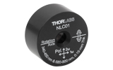 |
 |
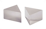 |
| Beamsplitters & Windows, 600 - 1500 nm or 1000 - 2000 nm |
Harmonic Beamsplitters, 400 nm and 800 nm or 500 nm and 1000 nm |
High-Power, Broadband, High Extinction Ratio Polarizers, 700 - 1300 nm | β-BBO Crystals for Second Harmonic Generation |
Dispersion-Compensating Mirrors, 650 - 1050 nm |
Dispersion-Compensating Prisms, 700 - 900 nm |
| Posted Comments: | |
| No Comments Posted |

| Key Specificationsa | ||
|---|---|---|
| Item # | NLCL4 | NLCL5 |
| Crystal Length | 10.00 mm | 20.00 mm |
| Angle of Optic Axis (θ, Φ)b | 90°, 13.6° | |
| Application | Type-I SHG | |
| AR Coating (AOI = 0°)c | R < 0.25% at 1030 nm and 515 nm | |
| Fundamental Wavelength (1ω) | 1030 nm | |
| SHG Wavelength (2ω) | 515 nm | |
| Implementation Guidelinesa | ||
|---|---|---|
| Item # | NLCL4 | NLCL5 |
| Recommended Operating Temperature | <60 °C | |
| Temperature Stabilityb | ±2.6 °C | ±1.4 °C |
| Minimum Recommended Focal Spot Size (1/e2 Diameter)c,d | 200 µm | 400 µm |
| Minimum Recommended Pulse Duration (FWHM)c | 0.50 ps | 1.00 ps |
| Phase Matching Bandwidth (FWHM)c | 3.0 nm | 1.5 nm |
| Recommended Oven (Optional)e | NLCH1(/M) or NLCH2(/M) | NLCH2(/M) |
- Mounted LBO Crystal with AR Coating for 515 nm and 1030 nm
- Designed for Type-I SHG with 1030 nm Nanosecond, Picosecond, Nd:YAG, Nd:YLF, and Yb:YAG Lasers
- Optional Crystal Oven for Temperature Stability Available Below (Sold Separately)
These LBO crystals are designed to produce type-I SHG emission at 515 nm from an input beam with a center wavelength of 1030 nm. They are available with lengths of 10.00 or 20.00 mm and feature an AR coating to reduce surface reflections at the fundamental and second harmonic wavelengths. The crystals are mounted in housings that are 21.0 mm wide, 10.8 mm tall, and 11.0 mm (Item # NLCL4) or 21.0 mm (Item # NLCL5) long, with a clear aperture of 2.7 mm x 2.7 mm. These mounted crystals can be used to frequency double the output of 1030 nm nanosecond and picosecond lasers such as Item # QSL103A. Please see the SHG and SFG Experimental Setups tab for an example of an SHG experimental setup.
Due to the LBO crystal length, the efficiency of SHG is highly sensitive to temperature and temperature fluctuations (please see the SHG Tutorial tab for more information). At a 0° angle of incidence, these crystals demonstrate peak SHG efficiency at around 20° C. To stabilize the SHG output, Thorlabs recommends using our Ovens for Nonlinear Crystals (sold separately below) for heating and temperature control. Please see the Guidelines tab for more information on the temperature requirements for the NLCL4 and NLCL5 LBO crystals.

| Key Specificationsa | |||
|---|---|---|---|
| Item # | NLCL1 | NLCL2 | NLCL3 |
| Crystal Length | 10.00 mm | 15.00 mm | 20.00 mm |
| Angle of Optic Axis (θ, Φ)b | 90°, 11.4° | ||
| Application | Type-I SHG | ||
| AR Coating (AOI = 0°)c | R < 0.25% at 1064 nm and 532 nm | ||
| Fundamental Wavelength (1ω) | 1064 nm | ||
| SHG Wavelength (2ω) | 532 nm | ||
| Implementation Guidelinesa | |||
|---|---|---|---|
| Item # | NLCL1 | NLCL2 | NLCL3 |
| Recommended Operating Temperature | <60 °C | ||
| Temperature Stabilityb | ±2.6 °C | ±1.8 °C | ±1.4 °C |
| Minimum Recommended Focal Spot Size (1/e2 Diameter)c,d | 175 µm | 260 µm | 350 µm |
| Minimum Recommended Pulse Duration (FWHM)c | 0.42 ps | 0.65 ps | 0.88 ps |
| Phase Matching Bandwidth (FWHM)c | 3.8 nm | 2.5 nm | 1.9 nm |
| Recommended Oven (Optional)e | NLCH1(/M) or NLCH2(/M) | NLCH2(/M) | |
- Mounted LBO Crystal with AR Coating for 532 nm and 1064 nm
- Designed for Type-I SHG with 1064 nm Nanosecond, Picosecond, Nd:YAG, Nd:YLF, and Yb:YAG Lasers
- Optional Crystal Oven for Temperature Stability Available Below (Sold Separately)
These LBO crystals are designed to produce type-I SHG emission at 532 nm from an input beam with a center wavelength of 1064 nm. They are available with lengths of 10.00, 15.00, or 20.00 mm and feature an AR coating to reduce surface reflections at the fundamental and second harmonic wavelengths. The crystals are mounted in housings that are 21.0 mm wide, 10.8 mm tall, and 11.0 mm (Item # NLCL1), 16.0 mm (Item # NLCL2), or 21.0 mm (Item # NLCL3) long, with a clear aperture of 2.7 mm x 2.7 mm. These mounted crystals can be used to frequency double the output of 1064 nm nanosecond and picosecond lasers such as Item # QSL106B. Please see the SHG and SFG Experimental Setups tab for an example of an SHG experimental setup.
Due to the LBO crystal length, the efficiency of SHG is highly sensitive to temperature and temperature fluctuations (please see the SHG Tutorial tab for more information). At a 0° angle of incidence, these crystals demonstrate peak SHG efficiency at around 20° C. To stabilize the SHG output, Thorlabs recommends using our Ovens for Nonlinear Crystals (sold separately below) for heating and temperature control. Please see the Guidelines tab for more information on the temperature requirements for the NLCL1, NLCL2, and NLCL3 LBO crystals.
The NLCL1, NLCL2, and NLCL3 crystals are optimized for type-I SHG of a 1064 nm input beam. Thorlabs also offers LBO crystals designed for non-critical phase matched SHG of the same wavelength (sold below), which can increase the SHG efficiency for lower power lasers without reducing the beam circularity.

| Key Specificationsa | ||
|---|---|---|
| Item # | NLCL8 | NLCL9 |
| Crystal Length | 20.00 mm | 30.00 mm |
| Angle of Optic Axis (θ, Φ)b | 90°, 0° | |
| Application | Non-Critical Phase Matched SHG | |
| AR Coating (AOI = 0°)c | R < 0.25% at 1064 nm and 532 nm | |
| Fundamental Wavelength (1ω) | 1064 nm | |
| SHG Wavelength (2ω) | 532 nm | |
| Implementation Guidelinesa | ||
|---|---|---|
| Item # | NLCL8 | NLCL9 |
| Recommended Operating Temperature | 150 °C | |
| Temperature Stabilityb | ±1.0 °C | ±0.8 °C |
| Minimum Recommended Focal Spot Size (1/e2 Diameter)c,d | 69 µm | 85 µm |
| Minimum Recommended Pulse Duration (FWHM)c | 0.88 ps | 1.30 ps |
| Phase Matching Bandwidth (FWHM)c | 1.9 nm | 1.3 nm |
| Recommended Ovene | NLCH2(/M) | |
- Mounted LBO Crystal with AR Coating for 532 nm and 1064 nm
- Designed for NCPM SHG with 1064 nm Nanosecond, Picosecond, Nd:YAG, Nd:YLF, and Yb:YAG Lasers
- Crystal Oven Required for Phase Matching (Sold Separately Below)
These LBO crystals are designed to produce NCPM SHG emission at 532 nm from an input beam with a center wavelength of 1064 nm. They are available with lengths of 20.00 or 30.00 mm and feature an AR coating to reduce surface reflections at the fundamental and second harmonic wavelengths. The crystals are mounted in housings that are 21.0 mm wide, 10.8 mm tall, and 21.0 mm (Item # NLCL8) or 31.0 mm (Item # NLCL9) long, with a clear aperture of 2.7 mm x 2.7 mm. These mounted crystals can be used to frequency double the output of 1064 nm nanosecond and picosecond lasers such as Item # QSL106B. Please see the SHG and SFG Experimental Setups tab for an example of an SHG experimental setup.
The NLCL8 and NLCL9 NCPM SHG crystals have a larger angular acceptance bandwidth compared to our type-I SHG crystals sold above. This allows for tighter focusing without reduction in circularity and increased SHG conversion efficiency with increased illumination intensity. Instead of angle tuning, non-critical phase matching is accomplished by tuning the temperature of the crystal. For a pump wavelength of 1064 nm, a crystal temperature of 150 °C is required for phase matching. For temperature control, Thorlabs recommends our NLCH2(/M) ovens for nonlinear crystals (sold separately below), which are specifically designed to hold these LBO crystals and provide high temperature stability. Please see the Guidelines tab for more information on the temperature requirements for the NLCL8 and NLCL9 LBO crystals.

| Key Specificationsa | ||
|---|---|---|
| Item # | NLCL6 | NLCL7 |
| Crystal Length | 10.00 mm | 15.00 mm |
| Angle of Optic Axis (θ, Φ)b | 42.4°, 90° | |
| Application | Type-II SFG | |
| AR Coating (AOI = 0°)c | R < 0.5% at 1064 nm, 532 nm, and 355 nm | |
| Fundamental Wavelengths (1ω + 2ω) | 1064 nm + 532 nm | |
| SFG Wavelength (3ω) | 355 nm | |
| Implementation Guidelinesa | ||
|---|---|---|
| Item # | NLCL6 | NLCL7 |
| Recommended Operating Temperature | <60 °C | |
| Temperature Stabilityb | ±1.4 °C | ±1.0 °C |
| Minimum Recommended Focal Spot Size (1/e2 Diameter)c,d | 221 µm | 330 µm |
| Minimum Recommended Pulse Duration (FWHM)c | 2.05 ps | 3.10 ps |
| Phase Matching Bandwidth (FWHM)c | 0.8 nm | 0.5 nm |
| Recommended Ovene | NLCH1(/M) or NLCH2(/M) | |
- Mounted LBO Crystal with AR Coating for 355 nm, 532 nm, and 1064 nm
- Designed for Type-II SFG with 1064 nm Nanosecond, Picosecond, Nd:YAG, Nd:YLF, and Yb:YAG Lasers in Combination with the Type-I or NCPM SHG Crystals Above
- No Need to Reorient Polarizations of the 1064 and 532 nm Beams
- Optional Crystal Oven for Temperature Stability Available Below (Sold Separately)
These LBO crystals are designed to produce third harmonic emission at 355 nm from type-II SFG of 1064 nm and its second harmonic 532 nm. They are available with lengths of 10.00 or 15.00 mm and feature an AR coating to reduce surface reflections at the fundamental, second harmonic, and sum frequency wavelengths. The crystals are mounted in housings that are 21.0 mm wide, 10.8 mm tall, and 11.0 mm (Item # NLCL6) or 16.0 mm (Item # NLCL7) long, with a clear aperture of 2.7 mm x 2.7 mm. When paired with one of the SHG crystals above, these mounted crystals can be used to generate 355 nm sum frequency photons from the output and second harmonic of 1064 nm nanosecond and picosecond lasers such as Item # QSL106B. Please see the SHG and SFG Experimental Setups tab for an example of an SFG experimental setup.
Due to the LBO crystal length, the efficiency of SFG is highly sensitive to temperature and temperature fluctuations (please see the SHG Tutorial tab for more information). At a 0° angle of incidence, these crystals demonstrate peak SHG efficiency at around 20° C. To stabilize the SFG output, Thorlabs recommends using our Ovens for Nonlinear Crystals (sold separately below) for heating and temperature control. Please see the Guidelines tab for more information on the temperature requirements for the NLCL6 and NLCL7 LBO crystals.

| Specifications | ||
|---|---|---|
| Item # | NLCH1(/M) | NLCH2(/M) |
| Crystal Length | Up to 15.00 mma | Up to 30.00 mma,b |
| Max Operating Temperature | 200 °C | |
| Clear Aperture | Ø0.18" (4.6 mm)c | |
| Beam Height | 1.00" (25.4 mm) | |
| Operating Voltage | 24 V | |
| Electrical Connection | 6-Pin Female Hirosed | |
| Dimensions (H x W x D) | 1.87" x 2.51" x 1.95" (47.4 mm x 63.8 mm x 49.5 mm) |
1.87" x 2.51" x 2.50" (47.4 mm x 63.8 mm x 63.5 mm) |
| Weight | 0.22 kg | 0.27 kg |
| Recommended Controllere | TC300B | |
- Heating from Ambient Temperature to 200 °C
- Compatible with Nonlinear LBO Crystals Above
- Options Available for Crystals up to 30.00 mm Long
- Requires a Temperature Controller Such as our TC300B Temperature Controller (Sold Separately Below)
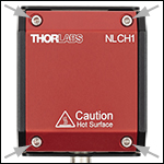
Click to Enlarge
Figure G5.1 Four screws on the top of the oven can be removed to open the cover and access the heater deck.
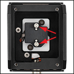
Click to Enlarge
Figure G5.2 Two interior screws can be removed to mount a nonlinear crystal in the ovens.
The NLCLH1(/M) and NLCLH2(/M) Ovens for Nonlinear Crystals are designed to provide temperature control and stability for the nonlinear LBO crystals sold above. Our LBO crystals with lengths up to 15.00 mm can be mounted in either oven while those with lengths from 20.00 to 30.00 mm can only be mounted in the NLCH2(/M) oven. To mount one of our LBO crystals, first remove the cover of the oven via the four M2.5 x 0.45 cap screws shown in Figure G5.1 and the two interior screws shown in Figure G5.2. Then place the crystal in the oven, aligning it with the two Ø2.0 mm dowel pins inside the oven. Finally, secure the crystal using the two cap screws previously removed from the oven's interior.
Each oven features four 4-40 threaded holes on the front and back faces, providing compatibility with our 30 mm Cage Systems for easy incorporation into an optical path. The ovens can be mounted directly to our PY005(/M) 5-Axis Stage via two of the Ø0.13" (3.2 mm) dowel pin holes on the bottom side of the oven (dowel pins not included) and the #8 (M4) central counterbore on the stage. The ovens require a temperature controller, such as our TC300B temperature controller (sold below) and can be connected to the controller using the included 6-pin Hirose cable. For more information on our nonlinear crystal ovens, please see the full web presentation.

| Key Specificationsa | |
|---|---|
| Output Power per Channel | 48 W (Max) |
| Output Current per Channel | 2 A (Max) |
| Output Voltage per Channel | 24 V (Max) |
| Temperature Setting Range | -200 to 400 °Cb |
| Set Point Resolution | 0.1 °C / 0.001 °Cc |
| Temperature Stability | ±0.1 °C |
| Output Connector Type | Hirose HR10A-7R-6S(73) |
| USB Interface | USB 2.0 Type-B |
| Power Supply | 100 - 240 VAC, 50 - 60 Hz, 165 VA Max |
| Operating Temperature | 0 - 40 °C |
| Storage Temperature | -15 - 65 °C |
| Dimensions (H x W x D) | 86.6 mm x 154.3 mm x 327.8 mm (3.41” x 6.07” x 12.91”) |
| Weight | 1.7 kg |
- Control Temperature from -200 °C to 400 °C
- Run Standalone or via Software
- Programmable PID with Auto-Tuning Functionality
The TC300B Heater and Thermoelectric Cooler (TEC) Temperature Controller is a two-channel benchtop controller intended for use with resistive heating elements and thermoelectric cooler devices rated up to 48 W. It can be used to provide temperature control from ambient to 200 °C for the nonlinear crystal ovens above. User-programmable maximum temperature and current/voltage limits protect the connected heating element from being overheated or over driven. Other safety features include an Open Sensor Alarm that will shut down the driver if the temperature sensing element is missing or becomes disconnected.
Capable of standalone operation from a simple keypad interface, this controller can also be connected to and controlled from a PC using the included USB Type-B cable and our TC300B Software, LabVIEW®* drivers, LabWindows drivers, or a simple command-line interface from any terminal window.
See the full web presentation for more information on the features of the TC300B controller.
*LabVIEW® is a registered trademark of National Instruments Corporation.
 Products Home


 Zoom
Zoom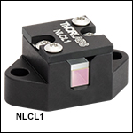

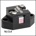


 LBO Crystals for SHG and SFG