High-Speed Optical Amplifier Instruments
- High Switching Speed of <1 ns
- Adjustable Power Up to 17 dBm or 18 dBm
- High Extinction Ratio of 70 dB
- Fiber-Coupled Optical Amplifier Device
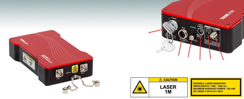
Key Switch
Power Supply Connector
Trigger Input
Trigger Mode Select
Drive Current
Interlock
HSB155AP
1550 nm High-Speed BOA Instrument
HSS155A
1550 nm High-Speed SOA Instrument

Please Wait
| Key Specificationsa | ||
|---|---|---|
| Item # | HSS155A | HSB155AP |
| Component Optical Shutter/Switch | SOA1013SXS | BOA1004PXS |
| Wavelength Range | 1528 nm - 1562 nm | 1530 nm - 1580 nm |
| Switching Speed | <1 ns | <1 ns |
| Small Signal Gain @ PIN = -20 dBmb | 13 dB | 25 dB |
| Extinction Ratio @ PIN = -20 dBmc | 70 dB | 70 dB |
| Max Output Power for Pulsed Input Signal | 17 dBm | 18 dBm |
| Max Output Power for CW Input Signal | 17 dBm | 18 dBm |
| Optical Isolation (PIN / POUT) @ 0 mAc | 60 dB (Min) | 60 dB (Min) |
Applications
- High Extinction Optical Switches
- Optical Signal Processing
- Microring Resonator Sensors
- Optical Time-Domain Reflectometry Systems
Click to Enlarge
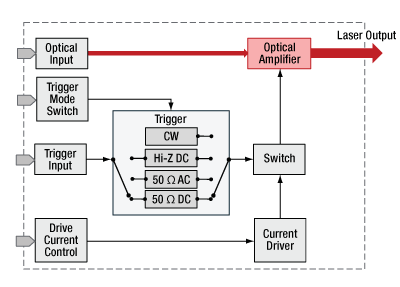
Figure 1.1 Block diagram depicting the four modes of operating the HS series amplifiers.
Features
- C-Band Amplification in 1550 nm Range
- Polarization-Dependent and Independent Versions
- Integrated Current Driver for High-Speed Switching
- Turnkey Operation with Temperature Control
Thorlabs' HS Series High-Speed Optical Amplifier Instruments integrate high-speed drivers and polarization-independent semiconductor optical amplifiers (SOAs) or polarization-dependent booster optical amplifiers (BOAs) to provide turnkey solutions for high-speed switching. These instruments provide high extinction ratios of 70 dB, ideal for optical shutter or switching applications.
Switching and pulsing operation is controlled through the TRIGGER INPUT port of this high-speed optical amplifier. Trigger mode options are continuous drive current (CW), Hi-Z for low-frequency operation (<1 MHz), and both AC- and DC-coupled 50 Ω triggering for high-frequency operation (>1 MHz). Output gain is produced by a variable current source, adjustable with discrete settings. With a high-speed, user-supplied trigger signal, switching speeds of <1 ns can be achieved using the input voltages specified in Table 2.3 on the Specs tab.
The drive electronics, temperature control circuits, and safety interlocks for these amplifier instruments are integrated into each device and are powered by an included DS15 power supply with a region-specific plug. Two FC/APC connectors serve as the fiber input and output ports for integration into fiber-terminated systems. Thorlabs stocks a variety of FC/APC terminated SM and PM fiber patch cables that may be used alongside these instruments.
Gain Control
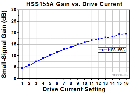
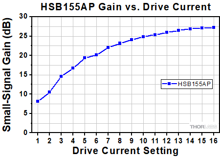
The gain for these amplifier instruments is controlled by adjusting the drive current in discrete steps, which are optimized for the individual device. The drive current selector on the back panel can be set to one of 16 positions using the included 2.5 mm screwdriver. When set to the MAX position, the typical operating current for each device will allow for the maximum output power to be achieved.
Triggering
Switching operation for these amplifier instruments is controlled by a user-provided electrical waveform, via the female SMA Trigger port on the back panel. For example, this device can produce an optical pulse from a user-supplied electrical pulse.
Four trigger mode options are available: continuous drive current (CW), Hi-Z suggested for low-frequency operation (<1 MHz), 50 Ω AC, or 50 Ω DC (with the last two options coupled for high-frequency operation greater than 1 MHz). The trigger mode control, located on the back panel, allows for the selection of each of these trigger modes.
Additional Front & Back Panel Features
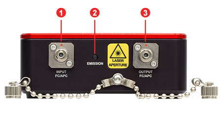
A dual-color (red/blue) emission indicator LED on the front panel indicates when laser output is enabled and is designed to be visible through most laser safety glasses.
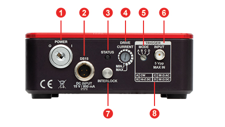
In addition to the trigger port, trigger mode control, and drive current control, a dual-color (red/green) status LED on the back panel indicates the operation state, including temperature stabilization and any errors. An engraved reference for the trigger mode options is also provided. Please see the Front & Back Panels tab and manual for more details about these features.
The HS series amplifiers have built-in safety features including a key switch, interlock pin, and a four-second delay between the emission LED illuminating and amplifier output.
Click to Enlarge
Click Here for Raw Data
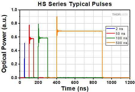
Figure 1.2 This plot shows the response of an HS Series Instrument seeded with a 1 mW distributed feedback (DFB) laser centered at 1550 nm, operating at a 1 MHz repetition rate when driven by an external pulse generator producing 2 ns, 50 ns, 100 ns, and 500 ns pulses.
Click to Enlarge
Click Here for Raw Data
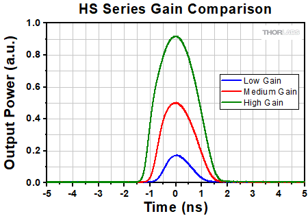
Figure 1.3 This plot shows the gain response for an HS Series Instrument at three different drive current settings, when seeded with a 1 mW distributed feedback (DFB) laser centered at 1550 nm. Low, Medium, and High Gain correspond to drive current positions 8, 12, and 16 respectively.
| Table 2.1 Polarization-Independent High-Speed SOA Instrument | |||
|---|---|---|---|
| Item # | HSS155A | ||
| Parameter | Min | Typical | Max |
| Operating Wavelength | 1528 nm | - | 1562 nm |
| Optical Isolation (PIN/POUT) @ 0 mA and 1550 nm | 60 dB | - | - |
| Extinction Ratio (On/Off @ PIN = -20 dBm and 1550 nm) | - | 70 dB | - |
| Switching Speed | - | <1 ns | - |
| Max Output Power for CW Input Signal | - | 17 dBm | - |
| Max Output Power for Pulsed Input Signal | - | 17 dBm | - |
| Saturation Output Power (@ -3 dB) | 12 dBm | 14 dBm | - |
| Small Signal Gaina (@ PIN = -20 dBm) | 10 dB | 13 dB | - |
| Fiber Specifications | |||
| Type (SM Fiber) | SMF-28 Ultra | ||
| Lengthb | 1.5 ± 0.1 m | ||
| Connector | FC/APC | ||
| Table 2.2 Polarization-Dependent High-Speed BOA Instrument | |||
|---|---|---|---|
| Item # | HSB155AP | ||
| Parameter | Min | Typical | Max |
| Operating Wavelength | 1530 nm | - | 1580 nm |
| Optical Isolation (PIN/POUT) @ 0 mA and 1550 nm | 60 dB | - | - |
| Extinction Ratio (On/Off @ PIN = -20 dBm and 1550 nm) | - | 70 dB | - |
| Switching Speed | - | <1 ns | - |
| Max Output Power for CW Input Signal | - | 18 dBm | - |
| Max Output Power for Pulsed Input Signal | - | 18 dBm | - |
| Saturation Output Power (@ -3 dB) | 13 dBm | 15 dBm | - |
| Small Signal Gaina (@ PIN = -20 dBm) | 22 dB | 25 dB | - |
| Fiber Specifications | |||
| Type (PM Fiber) | Corning PMF-1550 | ||
| Lengthb | 1.5 ± 0.1 m | ||
| Connector | FC/APC, Key Aligned to Slow Axis |
||
| Table 2.3 Trigger Specifications | |||
|---|---|---|---|
| Input Voltage | 50 Ω (AC Coupled)a | 0.2 - 5.0 Vpp | |
| 50 Ω (DC Coupled) | 0.2 - 5.0 V | ||
| Hi-Z, 5 kΩ (DC Coupled) | VIL | 0 - 0.8 V | |
| VIH | 2.2 - 5 V | ||
| Max Timing Jitter | 32 ps RMS | ||
| Max Input Frequency | 250 MHz | ||
| Delay from Trigger Input to Amplifier Rising Edgeb | 6 ± 1 ns | ||
| Delay from Trigger Input to Amplifier Falling Edgeb | 8.5 ± 1 ns | ||
| Delay from Trigger Input to Optical Outputc | 14 ± 2 ns | ||
| Table 2.5 Power, Environmental, and Physical Specifications | |
|---|---|
| AC Input Frequency Range to DS15 Power Supply |
50 Hz - 60 Hz |
| AC Input Voltage to DS15 Power Supply | 100 V - 240 V |
| DC Input Voltage Range to Instrument | 14.5 V - 15.5 V |
| DC Input Current to Instrument | 1000 mA (Max) |
| Operating Temperature Range | 10 °C to 45 °C |
| Storage Temperature Range | 0 °C to 60 °C |
| Humidity Range (Relative Humidity)a | 5% to 85% |
| Mass | 0.86 kg |
| Dimensions (L x W x H) | 185.6 mm x 100.0 mm x 39.4 mm (7.31" x 3.94" x 1.55") |
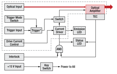
Click to Enlarge
Figure 2.4 Block diagram depicting the internal architecture of the laser control system with drive electronics, safety interlocks, and temperature stabilization. The multicolored status LED indicator (red/green/amber) blinks during the 30 to 60 s warm up and glows continuously once temperature stability has been achieved.
*Note: An expanded view of the Trigger is shown below

Click to Enlarge
Figure 2.6 Block diagram depicting the four modes of operating the HS series amplifiers.
Polarization-Independent High-Speed SOA Instrument
Click to Enlarge
Click Here for Raw Data
Average Small-Signal Gain Response of Two HSS155A Amplifiers for Each of 16 Discrete Drive Current Settings
Polarization-Dependent High-Speed BOA Instrument
Click to Enlarge
Click Here for Raw Data
Average Small-Signal Gain Response of Two HSB155AP Amplifiers for Each of 16 Discrete Drive Current Settings

Click to Enlarge
Click Here for Raw Data
This plot shows the response of an HS Series Instrument seeded with a 1 mW distributed feedback (DFB) laser centered at 1550 nm, operating at a 1 MHz repetition rate when driven by an external pulse generator producing 2 ns, 50 ns, 100 ns, and 500 ns pulses.

Click to Enlarge
Click Here for Raw Data
This plot shows the gain response for three different drive currents when an HS Series Instrument is seeded with a 1 mW distributed feedback (DFB) laser centered at 1550 nm. Low, Medium, and High Gain correspond to drive current positions 8, 12, and 16 respectively.
HS Series Front and Back Panels
| Front Panel | |
|---|---|
| Call Out | Description |
| 1 | Input Fiber Bulkhead (FC/APC), 2.0 mm Narrow Key |
| 2 | Emission Status LED, Dual Color (Red/Blue) |
| 3 | Output Fiber Bulkhead (FC/APC), 2.0 mm Narrow Key |
| Back Panel | |
|---|---|
| Call Out | Description |
| 1 | Power Key Switch |
| 2 | Male Mini-XLR Connector for the +15 V Power Supply Jack |
| 3 | LED Status Indicator, Dual Color (Red/Green) |
| 4 | Drive Current Controla |
| 5 | Trigger Mode Controla |
| 6 | Trigger Input Port (Female SMA Connector) |
| 7 | Interlock Jack, 2.5 mm Mono Phono (Interlock Pin Installed) |
| 8 | Chart of Trigger Modes |
Laser Safety and Classification
Safe practices and proper usage of safety equipment should be taken into consideration when operating lasers. The eye is susceptible to injury, even from very low levels of laser light. Thorlabs offers a range of laser safety accessories that can be used to reduce the risk of accidents or injuries. Laser emission in the visible and near infrared spectral ranges has the greatest potential for retinal injury, as the cornea and lens are transparent to those wavelengths, and the lens can focus the laser energy onto the retina.
Safe Practices and Light Safety Accessories
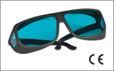
- Laser safety eyewear must be worn whenever working with Class 3 or 4 lasers.
- Regardless of laser class, Thorlabs recommends the use of laser safety eyewear whenever working with laser beams with non-negligible powers, since metallic tools such as screwdrivers can accidentally redirect a beam.
- Laser goggles designed for specific wavelengths should be clearly available near laser setups to protect the wearer from unintentional laser reflections.
- Goggles are marked with the wavelength range over which protection is afforded and the minimum optical density within that range.
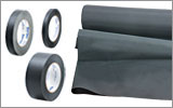
- Laser Safety Curtains and Laser Safety Fabric shield other parts of the lab from high energy lasers.
- Blackout Materials can prevent direct or reflected light from leaving the experimental setup area.
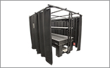
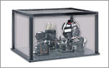
- Thorlabs' Enclosure Systems can be used to contain optical setups to isolate or minimize laser hazards.
- A fiber-pigtailed laser should always be turned off before connecting it to or disconnecting it from another fiber, especially when the laser is at power levels above 10 mW.
- All beams should be terminated at the edge of the table, and laboratory doors should be closed whenever a laser is in use.
- Do not place laser beams at eye level.
- Carry out experiments on an optical table such that all laser beams travel horizontally.
- Remove unnecessary reflective items such as reflective jewelry (e.g., rings, watches, etc.) while working near the beam path.
- Be aware that lenses and other optical devices may reflect a portion of the incident beam from the front or rear surface.
- Operate a laser at the minimum power necessary for any operation.
- If possible, reduce the output power of a laser during alignment procedures.
- Use beam shutters and filters to reduce the beam power.
- Post appropriate warning signs or labels near laser setups or rooms.
- Use a laser sign with a lightbox if operating Class 3R or 4 lasers (i.e., lasers requiring the use of a safety interlock).
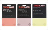
- Do not use Laser Viewing Cards in place of a proper Beam Trap.
Laser Classification
Lasers are categorized into different classes according to their ability to cause eye and other damage. The International Electrotechnical Commission (IEC) is a global organization that prepares and publishes international standards for all electrical, electronic, and related technologies. The IEC document 60825-1 outlines the safety of laser products. A description of each class of laser is given below:
| Class | Description | Warning Label |
|---|---|---|
| 1 | This class of laser is safe under all conditions of normal use, including use with optical instruments for intrabeam viewing. Lasers in this class do not emit radiation at levels that may cause injury during normal operation, and therefore the maximum permissible exposure (MPE) cannot be exceeded. Class 1 lasers can also include enclosed, high-power lasers where exposure to the radiation is not possible without opening or shutting down the laser. |  |
| 1M | Class 1M lasers are safe except when used in conjunction with optical components such as telescopes and microscopes. Lasers belonging to this class emit large-diameter or divergent beams, and the MPE cannot normally be exceeded unless focusing or imaging optics are used to narrow the beam. However, if the beam is refocused, the hazard may be increased and the class may be changed accordingly. |  |
| 2 | Class 2 lasers, which are limited to 1 mW of visible continuous-wave radiation, are safe because the blink reflex will limit the exposure in the eye to 0.25 seconds. This category only applies to visible radiation (400 - 700 nm). |  |
| 2M | Because of the blink reflex, this class of laser is classified as safe as long as the beam is not viewed through optical instruments. This laser class also applies to larger-diameter or diverging laser beams. |  |
| 3R | Class 3R lasers produce visible and invisible light that is hazardous under direct and specular-reflection viewing conditions. Eye injuries may occur if you directly view the beam, especially when using optical instruments. Lasers in this class are considered safe as long as they are handled with restricted beam viewing. The MPE can be exceeded with this class of laser; however, this presents a low risk level to injury. Visible, continuous-wave lasers in this class are limited to 5 mW of output power. |  |
| 3B | Class 3B lasers are hazardous to the eye if exposed directly. Diffuse reflections are usually not harmful, but may be when using higher-power Class 3B lasers. Safe handling of devices in this class includes wearing protective eyewear where direct viewing of the laser beam may occur. Lasers of this class must be equipped with a key switch and a safety interlock; moreover, laser safety signs should be used, such that the laser cannot be used without the safety light turning on. Laser products with power output near the upper range of Class 3B may also cause skin burns. |  |
| 4 | This class of laser may cause damage to the skin, and also to the eye, even from the viewing of diffuse reflections. These hazards may also apply to indirect or non-specular reflections of the beam, even from apparently matte surfaces. Great care must be taken when handling these lasers. They also represent a fire risk, because they may ignite combustible material. Class 4 lasers must be equipped with a key switch and a safety interlock. |  |
| All class 2 lasers (and higher) must display, in addition to the corresponding sign above, this triangular warning sign. |  |
|
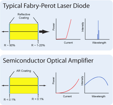
Booster optical amplifiers (BOAs) and semiconductor optical amplifiers (SOAs) are single-pass, traveling-wave amplifiers that perform well with both monochromatic and multi-wavelength signals. Since BOAs only amplify one state of polarization, they are best suited for applications where the input polarization of the light is known. For applications where the input polarization is unknown or fluctuates, SOAs are required. However, the gain, noise, bandwidth, and saturation power specifications of a BOA are superior to that of a SOA because of the design features that make the SOA polarization insensitive.
BOAs and SOAs are similar in design to Fabry-Perot Laser Diodes, the difference being that Fabry-Perot laser diodes have reflective coatings on both end faces of the semiconductor chip. The optical feedback from the reflective end faces establishes a cavity in which lasing can occur. SOAs and BOAs have an anti-reflection (AR) coating on both end faces of the semiconductor chip. The AR coatings limit the optical feedback into the chip so that lasing does not occur.
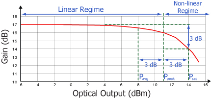
As is typical for all amplifiers, BOAs/SOAs operate in two regimes: a linear, flat, constant gain regime and a non-linear, saturated output regime. When used to amplify a modulated signal, the linear regime is typically used to eliminate pattern-dependent distortion, multi-channel cross-talk, and transient response issues common to EDFAs. The non-linear regime is used to take advantage of the highly non-linear attributes of the semiconductor gain medium (cross-gain modulation, cross phase modulation) to perform wavelength conversion, optical 3R regeneration, header recognition, and other high-speed optical signal processing functions.
For a continuous wave input signal, the amount of power that can be produced by the amplifier is determined by the saturation output power (Psat) parameter. Psat is defined as the output power at which the small-signal gain has been compressed by 3 dB. The maximum amount of CW power that can be extracted is approximately 3 dB higher than the saturation power.
| Posted Comments: | |
Zsolt Kis
(posted 2025-02-18 04:55:37.207) Dear Support Team,
I have a question about the input laser power of the amplifier. I looked at the transmission data of the HSB155AP amplifier for 1mW input. I found only about 20dB difference between the on/off periods. However, the spec. sheet mentions some 70dB extinction ratio. Was it just the measurement method which did not reveal the much stronger suppression of the input laser when the modulation signal is off, or the amplifier indeed cannot suppress so much the incoming laser beam?
Best regards,
Zsolt Kis EGies
(posted 2025-02-20 05:34:46.0) Thank you for contacting Thorlabs. The extinction (ON/OFF) ratio is defined as a combination of the optical isolation and the gain, and is indeed 70dB for the HSB155AP. Particularly at low input power levels, the OFF state power may be below the noise floor of a given detector. You would want to use the highest Drive Current setting to maximize the small signal gain and, accordingly, the extinction ratio. In the HS Series Typical Pulses graph (https://www.thorlabs.com/images/TabImages/HS_Series_Pulses_G2-780.gif) you mention, the detector did not have a sufficient resolution to resolve the OFF state power level. This graph is meant to illustrate the time domain performance. We have reached out to you directly regarding your specific application. |
 Products Home



 High-Speed Amplifier Instruments (BOAs & SOAs)