13.0 mm Travel Motorized Vertical Translation Stage
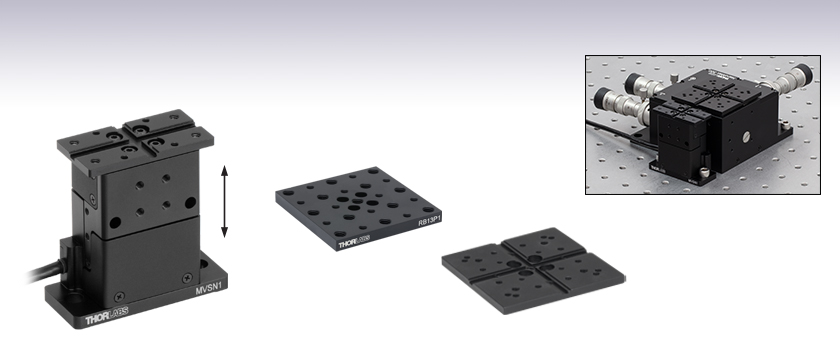
- 13.0 mm Vertical Travel
- Crossed-Roller Bearings for High Load Capacity and Straightness
- Removable Top Platform with 4-40 (M2 x 0.4) and 6-32 (M3 x 0.5) Taps
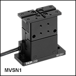
MVSN1
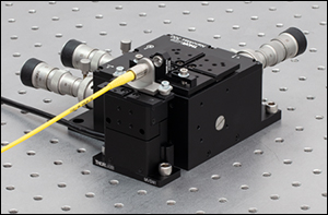
13.0 mm Travel Vertical Stage
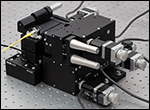
MVSN1 Stage with a MAX313D 3-Axis Stage
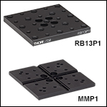
RB13P1
Replacement Plate with 1/4"-20 and 8-32 Taps
MMP1
Replacement Mounting Plate with 8-32, 6-32, and 4-40 Taps and Keyway Mounting Features

Please Wait
 Click to Enlarge
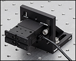
The MVSN1 Motorized Vertical Stage Mounted Horizontally with an AP90 Right-Angle Mounting Plate
Features
- 13.0 mm (0.51") of Vertical Travel
- Narrow 24.5 mm Width Along Optical Axis
- Open Loop Stepper Motor with Limit Switches
- Removable Top Plate
- Extended Top Platforms and Select Kinematic Platforms Can Be Used as Replacement Top Plates
- Mounting Holes for 1/4" (M6) Screws Provide Compatibility with Breadboards and Optical Tables
- Nominal Deck Height Matches That of Our Microblock™, RollerBlock™, and 3-Axis NanoMax™ Stages; Matches the Deck Height of Our 6-Axis NanoMax™ Stages with the Use of the MVSNB(/M) Height Spacer
- Black-Anodized Aluminum Construction
The MVSN1(/M) Motorized Vertical Translation Stage uses a stepper motor to provide 13.0 mm (0.51") of precise height adjustment and a working height range of 2.42" to 2.93" (61.5 mm to 74.5 mm). The top mounting plate has an array of four 4-40 (M2 x 0.4) and four 6-32 (M3 x 0.5) tapped holes, making it compatible with our range of keyway accessories for nanopositioning stages. Four M3 x 0.5 tapped holes on the side of the stage provide another option for securing mounting plates and other components. The stage can be used in restricted spaces due to its slender design and compact size, as well as in different orientations. The stage is constructed from black-anodized aluminum and includes crossed roller bearings for uniform performance over the entire range of motion.
The stage is designed to have the same nominal deck height as our Microblock™, RollerBlock™, and 3-Axis NanoMax™ stages. With the help of the MVSNB(/M) height spacer sold below, it can be used with our range of 6-Axis NanoMax™ stages.
The AP90(/M) Right-Angle Mounting Plate provides a convenient way to horizontally mount the MVSN1(/M) stage. When the stage is mounted on its side, its load capacity is limited by the maximum moment load.
 Click to Enlarge
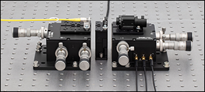
The MVSN1 Motorized Vertical Stage Used between a MAX313D 3-Axis Stage and a MAX312D 3-Axis Stage
Click to Enlarge
The MVSN1 Motorized Vertical Stage Used between a MAX313D 3-Axis Stage and a MAX312D 3-Axis StageIf needed, the top plate can be replaced with the MMP2B top plate, ideal for users who would like to machine their own custom mounting features. Extended top platforms with a similar grooved keyway, such as the MMP1(/M), RB13P1(/M), or AMA011(/M) top platforms sold below, are also available for use in applications that require extra reach beyond the edge of the vertical stage. Additionally, the MVSN1(/M) stage is compatible with some of our extension platforms, such as the AMA001(/M), AMA003(/M) or AMA005(/M) extended top platforms, as well as some of our kinematic platforms and stages, such as the APR001(/M), PY003(/M), APY001(/M), or APY002(/M) kinematic platforms. The stage can also be used with a MAX3SLH microscope slide holder.
Controller
Each stage has a female 15-Pin D-Sub port, allowing it to be controlled by a KST201 K-Cube™ controller, available below. The KST201 controller provides control for a single axis, with or without a PC. The controller can be operated from a PC using Thorlabs' Kinesis® software package, which features .NET controls that can be used by 3rd party developers working in the latest C#, Visual Basic, LabVIEW™, or any .NET compatible languages to create custom applications. Please see the Kinesis Software and Kinesis Tutorials tabs for more details.
Female 15-Pin D-Sub

| Pin | Description |
|---|---|
| 1 | GND Limit Switch |
| 2 | END (CCW) Limit Switch |
| 3 | HOME (CW) Limit Switch |
| 4 | Phase B- |
| 5 | Phase B+ |
| 6 | Phase A- |
| 7 | Phase A+ |
| 8 | Reserved for Future Use |
| 9 | Reserved for Future Use |
| 10 | +5 V |
| 11 | Reserved for Future Use |
| 12 | Reserved for Future Use |
| 13 | Reserved for Future Use |
| 14 | Reserved for Future Use |
| 15 | Reserved for Future Use |
Thorlabs' Kinesis® software features new .NET controls which can be used by third-party developers working in the latest C#, Visual Basic, LabVIEW™, or any .NET compatible languages to create custom applications.
C#
This programming language is designed to allow multiple programming paradigms, or languages, to be used, thus allowing for complex problems to be solved in an easy or efficient manner. It encompasses typing, imperative, declarative, functional, generic, object-oriented, and component-oriented programming. By providing functionality with this common software platform, Thorlabs has ensured that users can easily mix and match any of the Kinesis controllers in a single application, while only having to learn a single set of software tools. In this way, it is perfectly feasible to combine any of the controllers from the low-powered, single-axis to the high-powered, multi-axis systems and control all from a single, PC-based unified software interface.
The Kinesis System Software allows two methods of usage: graphical user interface (GUI) utilities for direct interaction and control of the controllers 'out of the box', and a set of programming interfaces that allow custom-integrated positioning and alignment solutions to be easily programmed in the development language of choice.
For a collection of example projects that can be compiled and run to demonstrate the different ways in which developers can build on the Kinesis motion control libraries, click on the links below. Please note that a separate integrated development environment (IDE) (e.g., Microsoft Visual Studio) will be required to execute the Quick Start examples. The C# example projects can be executed using the included .NET controls in the Kinesis software package (see the Kinesis Software tab for details).
 |
Click Here for the Kinesis with C# Quick Start Guide Click Here for C# Example Projects Click Here for Quick Start Device Control Examples |
 |
LabVIEW
LabVIEW can be used to communicate with any Kinesis-based controller via .NET controls. In LabVIEW, you build a user interface, known as a front panel, with a set of tools and objects and then add code using graphical representations of functions to control the front panel objects. The LabVIEW tutorial, provided below, provides some information on using the .NET controls to create control GUIs for Kinesis-driven devices within LabVIEW. It includes an overview with basic information about using controllers in LabVIEW and explains the setup procedure that needs to be completed before using a LabVIEW GUI to operate a device.
 |
Click Here to View the LabVIEW Guide Click Here to View the Kinesis with LabVIEW Overview Page |
 |
Software
Kinesis Version 1.14.51
The Kinesis Software Package, which includes a GUI for control of Thorlabs' Kinesis system controllers.
Also Available:
- Communications Protocol

Kinesis GUI Screen
Thorlabs offers the Kinesis® software package to drive our wide range of motion controllers. The software can be used to control devices in the Kinesis family, which covers a wide variety of motion controllers ranging from small, low-powered, single-channel drivers (such as the K-Cubes™) to high-power, multi-channel benchtop units and modular 19" rack nanopositioning systems (the MMR60x Rack System).
The Kinesis Software features .NET controls which can be used by 3rd party developers working in the latest C#, Visual Basic, LabVIEW™, or any .NET compatible languages to create custom applications. Low-level DLL libraries are included for applications not expected to use the .NET framework and APIs are included with each install. A Central Sequence Manager supports integration and synchronization of all Thorlabs motion control hardware.
By providing this common software platform, Thorlabs has ensured that users can mix and match any of our motion control devices in a single application, while only having to learn a single set of software tools. In this way, it is perfectly feasible to combine any of the controllers from single-axis to multi-axis systems and control all from a single, PC-based unified software interface.
The software package allows two methods of usage: graphical user interface (GUI) utilities for direct interaction with and control of the controllers 'out of the box', and a set of programming interfaces that allow custom-integrated positioning and alignment solutions to be easily programmed in the development language of choice.
Multi-Axis Stage Selection Guide
Click to Enlarge
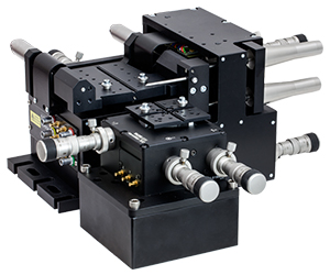
In the above application, a 3-Axis NanoMax flexure stage is aligned in front of a 6-axis stage at the proper 112.5 mm deck height using an AMA554 Height Adapter.
3-Axis Stages
Thorlabs offers three different 3-Axis Stage variations: NanoMax flexure stages, MicroBlock compact flexure stages, and RollerBlock long-travel stages. Each stage features a 62.5 mm nominal deck height. Our NanoMax line of 3-axis stages offers built-in closed- and open-loop piezos as well as modular drive options that include stepper motors, differential drives, or additional piezos. The MicroBlock stages are available with differential micrometer drives or fine thread thumbscrews; these drives are not removable. Finally, our RollerBlock stage drivers can be switched out for any actuator that has a Ø3/8" (9.5 mm) mounting barrel.
4- and 5-Axis Stages
Our 4- and 5-axis stages are ideal for the static positioning of waveguides or complex optical elements with respect to our 3-axis or 6-axis high-performance alignment stages. Thorlabs' 5-axis stages have nominal heights of 62.5 mm or 112.5 mm. The AMA554 Height Adapter can be used to raise the deck height of the 3-axis or 4-axis stages to 112.5 mm for compatibility with our 5-axis MicroBlock or 6-Axis NanoMax Stages.
6-Axis Stages
Thorlabs' 6-Axis NanoMax Nanopositioners are ideal for complex, multi-axis positioning and have a nominal deck height of 112.5 mm. These stages offer a common point of rotation and a patented parallel flexure design that allows all actuators to be coupled directly to the base to minimize any unwanted motion in the system. Built-in closed- and open-loop piezo options are available. A selection of modular drive options allows any axis to be manual or motorized with the option for external piezos. Our units without included actuators are also available in right- or left-handed configurations. To increase the stage height of the 3-axis stages to 112.5 mm, we recommend our AMA554 Height Adapter, shown in the image to the right.
A complete selection and comparison of our multi-axis stages is available below.
3-Axis Stages
| Item # | MAX313D | MAX312D | MAX311D | MAX383 | MAX381 | MAX303 | MAX302 | MAX301 | MBT602 | MBT616D | RB13M | RBL13D | ||||||||
|---|---|---|---|---|---|---|---|---|---|---|---|---|---|---|---|---|---|---|---|---|
| Stage Type | NanoMax Flexure Stages | MicroBlock Compact Flexure Stages |
RollerBlock Long Travel Stages | |||||||||||||||||
| Included Drives | DRV3 Differential Micrometers | DRV208 Stepper Motor Actuators | N/A | Fine Thread Thumbscrews | Differential Micrometers | 148-801ST Micrometer Drives |
DRV304 Differential Micrometers |
|||||||||||||
| Built-in Piezos | N/A | Open Loop |
Closed Loop | N/A | Closed Loop | N/A | Open Loop | Closed Loop | N/A | N/A | ||||||||||
| Travel (X, Y, Z) | 4 mm (0.16") | 13 mm (0.51") | ||||||||||||||||||
| Deck Height (Nominal) | 62.5 mm (2.46") | |||||||||||||||||||
| Optical Axis Height (Nominal) | 75 mm (2.95") | |||||||||||||||||||
| Load Capacity (Max) | 1 kg (2.2 lbs) | 4.4 kg (9.7 lbs) | ||||||||||||||||||
| Thermal Stability | 1 µm/°C | - | ||||||||||||||||||
| Weight | 1.00 kg (2.20 lbs) | 0.64 kg (1.40 lbs) | 0.59 kg (1.30 lbs) | |||||||||||||||||
4-Axis Stages
| Item # | MBT401D MBT401D/M |
MBT402D MBT402D/M |
|
|---|---|---|---|
| Stage Type | 4-Axis Thin-Profile MicroBlock Device Stage | 4-Axis Low-Profile MicroBlock Device Stage | |
| Included Drives | Differential Micrometers | ||
| Built-in Piezos | N/A | ||
| Travel | Horizontal Axis (Y)a | 13 mm (0.51") | |
| Vertical Axis (Z) | 6 mm (0.24") | ||
| Pitch (θy) | ±5° | ||
| Yaw (θz) | ±5° | ||
| Deck Height (Nominal) | 62.5 mm (2.46") | ||
| Optical Axis Height (Nominal) | 75 mm (2.95") | ||
| Load Capacity (Max) | 0.5 kg (1.1 lbs) | ||
5-Axis Stages
| Item # | MBT401D (MBT401D/M) or MBT402D (MBT402D/M) with MBT501 |
PY005 | |
|---|---|---|---|
| Stage Type | 5-Axis MicroBlock Stage System | Compact 5-Axis Stage | |
| Included Drives | Differential Micrometers | 100 TPI Actuators | |
| Built-in Piezos | N/A | ||
| Travel | Optical Axis (X) | 13 mm (0.51") | 3 mm (0.12") |
| Horizontal Axis (Y) | 13 mm (0.51") | 3 mm (0.12") | |
| Vertical Axis (Z) | 6 mm (0.24") | 3 mm (0.12") | |
| Pitch (θy) | ±5° | ±3.5° | |
| Yaw (θz) | ±5° | ±5° | |
| Deck Height (Nominal) | 112.5 mm (4.43") | 62.5 mm (2.46")a | |
| Optical Axis Height (Nominal) | 125 mm (4.92") | 75 mm (2.95")a | |
| Load Capacity (Max) | 0.5 kg (1.1 lbs) | 0.23 kg (0.5 lbs) | |
6-Axis Stages
| Item # | MAX601D MAX601D/M |
MAX602D MAX602D/M |
MAX603D MAX603D/M |
MAX681 MAX681/M |
MAX682 MAX682/M |
MAX683 MAX683/M |
MAX607 MAX607/M MAX607La MAX607L/Ma |
MAX608 MAX608/M MAX608La MAX608L/Ma |
MAX609 MAX609/M MAX609La MAX609L/Ma |
|
|---|---|---|---|---|---|---|---|---|---|---|
| Stage Type | 6-Axis NanoMax Flexure Stage | |||||||||
| Included Drives | DRV3 Differential Micrometers | DRV208 Stepper Motor Actuators | N/A | |||||||
| Built-in Piezos | N/A | Open Loop | Closed Loop | N/A | Open Loop | Closed Loop | N/A | Open Loop | Closed Loop | |
| Travel | X, Y, Z | 4 mm (0.16") | ||||||||
| θx, θy, θz | 6° | |||||||||
| Deck Height (Nominal) | 112.5 mm (4.43") | |||||||||
| Optical Axis Height (Nominal) | 125 mm (4.92") | |||||||||
| Load Capacity (Max) | 1.0 kg (2.2 lbs) | |||||||||
| Posted Comments: | |
| No Comments Posted |
Motorized Linear Translation Stages
Thorlabs' motorized linear translation stages are offered in a range of maximum travel distances, from a stage with 20 µm of piezo translation to our 600 mm direct drive stage. Many of these stages can be assembled in multi-axis configurations, providing XY or XYZ translation. For fiber coupling applications, please see our multi-axis stages, which offer finer adjustment than our standard motorized translation stages. In addition to motorized linear translation stages, we offer motorized rotation stages and goniometers. We also offer manual translation stages.
Piezo Stages
These stages incorporate piezoelectric elements in a variety of drive mechanisms. ORIC® stages incorporate piezo inertia drives that use "stick-slip" friction properties to obtain extended travel ranges. Our modular, quick-connect XR25 series translation stage can be driven by the PIA25 piezo inertia actuator which operates using the same principle. Our Nanoflex™ translation stages use standard piezo chips along with manual actuators. Elliptec® stages use resonant piezo motors to push and pull the moving platform through resonant elliptical motion. Our LPS710E z-axis stage features a mechanically amplified piezo design and includes a matched controller.
| Piezoelectric Stages | ||||
|---|---|---|---|---|
| Product Family | ORIC® PDXZ1 Closed-Loop 4.5 mm Vertical Stage |
ORIC® PD2 Open-Loop 5 mm Stage |
ORIC® PDX2 Closed-Loop 5 mm Stage |
|
| Click Photo to Enlarge |
 |
 |
 |
|
| Travel | 4.5 mm | 5 mm | ||
| Speed | 1 mm/s (Typ.)a | 10 mm/s (Typ. Max)b | 8 mm/s (Typ.)c | |
| Drive Type | Piezoelectric Inertia Drive | |||
| Possible Axis Configurations | Z | X, XY, XYZ | ||
| Mounting Surface Size | 45.0 mm x 42.0 mm | 13 mm x 13 mm | ||
| Additional Details | ||||
| Piezoelectric Stages | |||||
|---|---|---|---|---|---|
| Product Family | ORIC® PD1 Open-Loop 20 mm Stage |
ORIC® PD1D Open-Loop 20 mm Monolithic XY Stage |
ORIC® PDX1 Closed-Loop 20 mm Stage |
ORIC® PD3 Open-Loop 50 mm Stage |
|
| Click Photo to Enlarge |
 |
 |
 |
 |
|
| Travel | 20 mm | 50 mm | |||
| Speed | 3 mm/s (Typ. Max)a | 20 mm/s (Typ. Max)b | 10 mm/sc | ||
| Drive Type | Piezoelectric Inertia Drive | ||||
| Possible Axis Configurations | X, XY, XYZ | XY, XYZ | X, XY, XYZ | X, XY, XYZ | |
| Mounting Surface Size | 30 mm x 30 mm | 80 mm x 30 mm | |||
| Additional Details | |||||
| Piezoelectric Stages | |||||||
|---|---|---|---|---|---|---|---|
| Product Family | Nanoflex™ 20 µm Stage with 5 mm Actuator |
Nanoflex™ 25 µm Stage with 1.5 mm Actuator |
Modular XR25 Series 25 mm Stage |
Elliptec® 28 mm Stage | Elliptec® 60 mm Stage | LPS710E 1.1 mm Vertical Stage | |
| Click Photo to Enlarge |
 |
 |
 |
 |
 |
 |
|
| Travel | 20 µm + 5 mm Manual | 25 µm + 1.5 mm Manual | 25 mm | 28 mm | 60.0 mm | 1.1 mm | |
| Maximum Velocity | - | ≤3.6 mm/mina | 180 mm/s | 90 mm/s | - | ||
| Drive Type | Piezo with Manual Actuator | Piezo Inertia Drive | Resonant Piezoelectric Motor | Amplified Piezo | |||
| Possible Axis Configurations | X, XY, XYZ | X, XY, YZ, XZ, XYZ | X | Z | |||
| Mounting Surface Size | 75 mm x 75 mm | 30 mm x 30 mm | 110.0 mm x 75.7 mm | 15 mm x 15 mm | 21 mm x 21 mm | ||
| Additional Details | |||||||
Stepper Motor Stages
These translation stages feature removable or integrated stepper motors and long travel ranges up to 300 mm. Many of these stages either have integrated multi-axis capability (PLSXY) or can be assembled into multi-axis configurations (PLSX, Quick-Connect XR25 Series, LNR Series, NRT Series, and LTS Series stages). The MLJ150 stage also offers high load capacity vertical translation.
| Stepper Motor Stages | |||||
|---|---|---|---|---|---|
| Product Family | MVSN1(/M) 13 mm Vertical Stage | PLS Series 1" Stages |
Modular XR25 Series 25 mm Stage |
LNR Series 25 mm Stage |
LNR Series 50 mm Stage |
| Click Photo to Enlarge |
 |
 |
 |
 |
 |
| Travel | 13 mm | 1" (25.4 mm) | 25 mm | 25 mm | 50 mm |
| Maximum Velocity | 5.0 mm/s | 7.0 mm/s | 2.0 mm/s | 2.0 mm/s | 50 mm/s |
| Possible Axis Configurations | Z | X, XY | X, XY, YZ, XZ, XYZ | X, XY, XYZ | X, XY, XYZ |
| Mounting Surface Size | 24.5 mm x 50.0 mm | 3" x 3" (76.2 mm x 76.2 mm) | 110.0 mm x 75.7 mm | 60 mm x 60 mm | 100 mm x 100 mm |
| Additional Details | |||||
| Stepper Motor Stages | ||||||
|---|---|---|---|---|---|---|
| Product Family | NRT Series 100 mm Stage |
NRT Series 150 mm Stage |
LTS Series 150 mm Stage |
LTS Series 300 mm Stage |
MLJ250 50 mm Vertical Stage |
|
| Click Photo to Enlarge |
 |
 |
 |
 |
 |
|
| Travel | 100 mm | 150 mm | 150 mm | 300 mm | 50 mm | |
| Maximum Velocity | 30 mm/s | 50 mm/s | 3.0 mm/s | |||
| Possible Axis Configurations | X, XY, XYZ | X, XY, XYZ | Z | |||
| Mounting Surface Size | 84 mm x 84 mm | 100 mm x 90 mm | 148 mm x 131 mm | |||
| Additional Details | ||||||
DC Servo Motor Stages
Thorlabs offers linear translation stages with removable or integrated DC servo motors. These stages feature low profiles and many can be assembled in multi-axis configurations.
| DC Servo Motor Stages | |||||
|---|---|---|---|---|---|
| Product Family | MT Series 12 mm Stages |
PT Series 25 mm Stages |
Modular XR25 Series 25 mm Stage |
MTS Series 25 mm Stage |
MTS Series 50 mm Stage |
| Click Photo to Enlarge |
 |
 |
 |
 |
 |
| Travel | 12 mm | 25 mm | 25 mm | 25 mm | 50 mm |
| Maximum Velocity | 2.6 mm/s | 2.6 mm/s | 2.4 mm/s | ||
| Possible Axis Configurations | X, XY, XYZ | X, XY, YZ, XZ, XYZ | X, XY, XYZ | ||
| Mounting Surface Size | 61 mm x 61 mm | 101.6 mm x 76.2 mm | 110.0 mm x 75.7 mm | 43 mm x 43 mm | |
| Additional Details | |||||
| DC Servo Motor Stages | ||||
|---|---|---|---|---|
| Product Family | M30 Series 30 mm Stage |
M30 Series 30 mm Monolithic XY Stage |
M150 Series 150 mm XY Stage |
KVS30 30 mm Vertical Stage |
| Click Photo to Enlarge |
 |
 |
 |
 |
| Travel | 30 mm | 150 mm | 30 mm | |
| Maximum Velocity | 2.4 mm/s | X-Axis: 170 mm/s Y-Axis: 230 mm/s |
8.0 mm/s | |
| Possible Axis Configurations | X, Z | XY, XZ | XY | Z |
| Mounting Surface Size | 115 mm x 115 mm | 272.4 mm x 272.4 mm | 116.2 mm x 116.2 mm | |
| Additional Details | ||||
Direct Drive Stages
These low-profile stages feature integrated brushless DC servo motors for high speed translation with zero backlash. When no power is applied, the platforms of these stages have very little inertia and are virtually free running. Hence these stages may not be suitable for applications where the stage's platform needs to remain in a set position when the power is off. We do not recommend mounting these stages vertically.
| Direct Drive Stages | |||||
|---|---|---|---|---|---|
| Product Family | DDS Series 50 mm Stage |
DDS Series 100 mm Stage |
DDS Series 220 mm Stage |
DDS Series 300 mm Stage |
DDS Series 600 mm Stage |
| Click Photo to Enlarge |
 |
 |
 |
 |
 |
| Travel | 50 mm | 100 mm | 220 mm | 300 mm | 600 mm |
| Maximum Velocity | 500 mm/s | 300 mm/s | 400 mm/s | 400 mm/s | |
| Possible Axis Configurations | X, XY | X, XY | X | X | |
| Mounting Surface Size | 60 mm x 52 mm | 88 mm x 88 mm | 120 mm x 120 mm | ||
| Additional Details | |||||

 Click to Enlarge
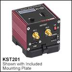
The MVSN1 Motorized Vertical Stage with a KST201 K-Cube™ Controller
- 13.0 mm (0.51") of Vertical Travel
- Array of 4-40 (M2 x 0.4) and 6-32 (M3 x 0.5) Tapped Mounting Holes
The MVSN1(/M) Motorized Vertical Stage provides 13.0 mm (0.51") of height adjustment, an array of 4-40 (M2 x 0.4) and 6-32 (M3 x 0.5) tapped holes, and a load capacity of 10 N. The top plate is attached using four M3 x 0.5-threaded button head screws with 2.0 mm (5/64") hex heads. If needed, the top plate can be replaced with the MMP2B top plate, ideal for users who would like to machine their own custom mounting features. Extended top platforms with a similar grooved keyway, such as the MMP1(/M), RB13P1(/M), or AMA011(/M) top platforms sold below, are also available for use in applications that require extra reach beyond the edge of the vertical stage. Additionally, the MVSN1(/M) stage is compatible with our kinematic platforms and stages, such as the APR001(/M), PY003(/M), APY001(/M), or APY002(/M) kinematic platforms. The stage can also be used with a MAX3SLH microscope slide holder.
The stage is designed so that its nominal deck height matches the nominal deck height of our Microblock™, RollerBlock™, and 3-Axis NanoMax™ stages. With the help of the MVSNB(/M) height spacer sold below, it can be used with our range of 6-Axis NanoMax™ stages.

The MVSNB(/M) Height Spacer raises the operational height of the MVSN1(/M) Motorized Vertical Stage by 1.69" (43.0 mm) so that it can be used with our range of 6-Axis NanoMax™ stages. The height spacer can be used to mount an MVSN1(/M) stage next to a right-handed MAX600 stage when the height spacer is positioned right-side up or a left-handed MAX600 stage when the spacer is upside-down.
The 1/4"-20 (M6 x 1.0) mounting holes can also be used with other 1/4"-20 (M6 x 1.0) compatible products, such as Ø1/2" Optical Posts.
To mount the MVSNB(/M) Height Spacer and MVSN1(/M) Stage, insert two 1/4" (M6) cap screws (1.77" (45.0 mm) shank length recommended) through each of the slots in the height spacer and mount it on an even surface. Depending on the length of the screws and the surface the spacer is being mounted to, washers may be required. Then, position the MVSN1(/M) stage on top of the MVSNB(/M) Height Spacer and secure using two 1/4"-20 (M6 x 1.0) screws (0.59" (15.0 mm) shank length recommended).

 Click to Enlarge
The MVSN1 Motorized Vertical Stage with its top plate mounted on its side and an MMP2B Narrow Top Plate
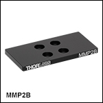
The MMP2B Blank Narrow Top Plate is intended for use with the MVSN1(/M) Motorized Vertical Stage. If the top plate of the MVSN1(/M) stage is taken off and used with the side mounting holes on the stage, the MMP2B blank top plate can be used to cover the internals of the stage. It is also ideal for machining custom mounting features.
To mount the MMP2B top plate, first, remove any existing top plate that you wish to replace from the stage, keeping the four 5/64" (2.0 mm) hex M3 x 0.5 button head cap screws. Then, position the MMP2B top plate in the desired orientation and secure it to the stage using the M3 x 0.5 threaded mounting holes and four M3 button head cap screws. Ensure the screws are tightened appropriately and the top plate does not move. Alternatively, the SH3M06B M3 Button Head Cap Screws can be purchased separately for applications where more than one plate is installed on the stage at the same time.

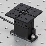 Click to Enlarge
The MVSN1 Motorized Vertical Stage Used with an MMP1 Top Plate
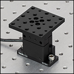 Click to Enlarge
The MVSN1 Motorized Vertical Stage Used with an RB13P1 Adapter Plate
- RB13P1(/M) Adapter Plate for General Purpose Accessories and Components
- Array of Thirteen 1/4"-20 (M6) and Twelve 8-32 (M4) Tapped Mounting Holes
- MMP1(/M) Standard 3-Axis Stage Top Plate (Included with All 3-Axis Stages)
- Two 3 mm Wide Central Keyways for Aligning Multi-Axis Stage Accessories
- Sixteen 6-32 (M3) Taps for Mounting Cleats
- Four 4-40 (M2) Taps
- Nine 8-32 (M4) Taps
- Provide a Larger 2.36" x 2.36" Mounting Surface, but Increase the Footprint of the Stage
The RB13P1(/M) Mounting Plate can be used as an alternative to the top plate included with our MVSN1(/M) stage. Its 2.36" x 2.36" mounting surface has a generous array of both 1/4"-20 (M6) and 8-32 (M4) mounting holes to adapt the MVSN1(/M), 3-Axis NanoMax™, MicroBlock™, or RollerBlock™ stages to general-purpose optical table translation stages. Four counterbores that accept M3 screws allow it to be attached to the above stages.
The MMP1(/M) Mounting Plate is included with all 3-Axis NanoMax™, MicroBlock™, or RollerBlock™ stages and features a 'crossed groove' design, which is necessary for many flexure stage accessories. The mounting plate is compatible with the MVSN1(/M) Motorized Vertical Stage. The 2.36" x 2.36" mounting surface contains an array of 4-40 (M2), 6-32 (M3), and 8-32 (M4) tapped mounting holes for securing and mounting various components. For complete details on the dimensions and tap locations of these top plates, please see the mechanical drawings accessible by clicking on the red docs icon (![]() ) next to the Item #.
) next to the Item #.

 Click to Enlarge
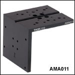
The MVSN1 Motorized Vertical Stage Used with an AMA011 Right-Angle Bracket
- Right-Angle Bracket Adds a Side Mounting Surface
- Replaces the Top Plates Included with MVSN1(/M), 3-Axis NanoMax™, or MicroBlock™ 3-Axis Stages
- Included Top Surface Mounting Features
- Groove for Mounting Keyway Accessories
- Seven 8-32 (M4 x 0.7) Tapped Holes
- Eight 6-32 (M3 x 0.5) Tapped Holes
- Side Mounting Surface Includes Eight 6-32 (M3 x 0.5) Tapped Holes
- Provides a Larger Mounting Surface, but Increases the Footprint of the Stage
The AMA011(/M) Right-Angle Bracket can be used to replace the top plate of our MVSN1(/M) stage or our 3-axis flexure stages (3-Axis NanoMax™ or MicroBlock™) stages. The 2.36" x 2.68" top surface of the bracket provides a groove for mounting Keyway Accessories, seven 8-32 (M4 x 0.7) tapped holes, and eight 6-32 (M3 x 0.5) tapped holes, while the convenient 2.36" x 2.30" side mounting surface features eight 6-32 (M3 x 0.5) tapped holes for attaching other components or accessories to the stage.
Note that moving the platform on the stage will also move any mounted accessories.

- Front Panel Velocity Wheel and Digital Display for Controlling Motorized Stages or Actuators
- Two Bidirectional Trigger Ports to Read or Control External Equipment
- Interfaces with Computer Using Included USB Cable
- Fully Compatible with Kinesis® Software Package
- Compact Footprint: 60.0 mm x 60.0 mm x 49.2 mm (2.42" x 2.42" x 1.94")
- Power Supply Not Included (See Below)
Thorlabs' KST201 K-Cube™ Stepper Motor Controller provides local and computerized control of a single motor axis. It features a top-mounted control panel with a velocity wheel that supports variable-speed bidirectional control with forward and reverse jogging as well as position presets. The digital display on the top panel includes a backlight that can be dimmed or turned off using the top panel menu options. The front of the unit contains two bidirectional trigger ports that can be used to read a 5 V external logic signal or output a 5 V logic signal to control external equipment. Each port can be independently configured to control the logic level or to set the trigger as an input or output.
The unit is fully compatible with our Kinesis software package. Please see the Kinesis Software tab for more information.
Please note that this controller does not ship with a power supply. Compatible power supplies are listed below.
Please see the full KST201 controller web presentation for more information.

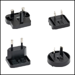
Click for Details
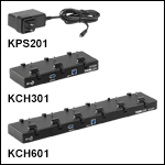
Each KPS201 power supply includes one region-specific adapter, which can be selected upon checkout.
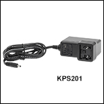
Click to Enlarge
The KPS201 Power Supply Unit
- Individual Power Supply
- KPS201: For K-Cubes™ or T-Cubes™ with 3.5 mm Jacks
- USB Controller Hubs Provide Power and Communications
- KCH301: For up to Three K-Cubes or T-Cubes
- KCH601: For up to Six K-Cubes or T-Cubes
The KPS201 power supply outputs +15 VDC at up to 2.66 A and can power a single K-Cube or T-Cube with a 3.5 mm jack. It plugs into a standard wall outlet.
The KCH301 and KCH601 USB Controller Hubs each consist of two parts: the hub, which can support up to three (KCH301) or six (KCH601) K-Cubes or T-Cubes, and a power supply that plugs into a standard wall outlet. The hub draws a maximum current of 10 A; please verify that the cubes being used do not require a total current of more than 10 A. In addition, the hub provides USB connectivity to any docked K-Cube or T-Cube through a single USB connection.
For more information on the USB Controller Hubs, see the full web presentation.

- Can be Used to Secure Top Plates and Top Platforms to MVSN1(/M), 3- and 6-Axis NanoMax™, MicroBlock™, RollerBlock™, MVS05(/M), or MVS1(/M) Stages
- 6 mm Long
The SH3M06B Button Head Socket Cap Screws are M3 x 0.5 button head cap screws with a 2.0 mm (5/64") hex. They are made from grade 10.9 alloy steel with a black nickel coating, and can be used to secure various top plates and top platforms to MVSN1(/M) stages, as well as 3- and 6-Axis NanoMax™, MicroBlock™, or RollerBlock™ stages. They can also be used to mount various top plates and top platforms to MVS05(/M) and MVS1(/M) stages.
 Products Home


 Click to Enlarge
 Zoom
Zoom
 Click to Enlarge

 Linear: 13 mm Motorized Vertical Stage