 Products Home / Imaging Systems / OCT Imaging Systems & Components / OCT Components / MEMS-VCSEL Swept-Wavelength Laser Sources
MEMS-VCSEL Swept-Wavelength Laser Sources

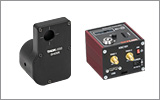
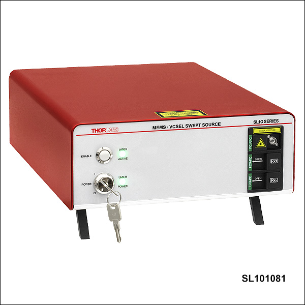
SL101081
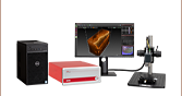
1060 nm MEMS-VCSEL Swept Source
Fixed Mode, 400 kHz Sweep Rate,
Integrated Balanced Detector
- Available with 1060 nm or 1300 nm Center Wavelength
- Sweep Rates from 50 kHz to 1 MHz
- Over 100 mm Coherence Length
- Single Mode, Mode-Hop-Free Operation
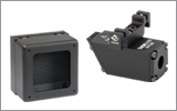
SLZ1302
1300 nm MEMS-VCSEL Swept Source
Three Selectable Modes, 1 MHz Max Sweep Rate, Integrated Balanced Detector, Dual-Channel Configuration


Please Wait
| Quick Comparisona | ||||
|---|---|---|---|---|
| Item # | SL10xxx0, SL13xxx0 |
SL10xxx1, SL13xxx1 |
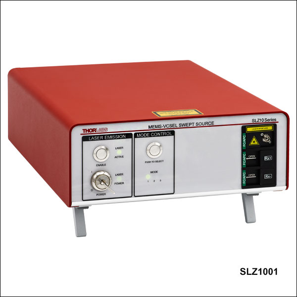
SLZ1001, SLZ1301 |
SLZ1002, SLZ1302 |
| Wavelength Sweep Range (-10 dB) | 100 nm (Typ.) | Up to 100 nm (Typ.)b | ||
| Coherence Length | ≥100 mm | |||
| Relative Intensity Noise (RIN) | ≤2% | |||
| Feature Comparison | ||||
| MZI Configurations/Modes | One | Three | ||
| Sweep Rate | Fixed (50 to 400 kHz)c |
Selectable (Up to 400 kHz)d |
Selectable (Up to 1 MHz)d |
|
| Data Acquisition Configuration | k-Clocking | k-Clocking | k-Clocking | Dual Channel |
| Digital k-Clock Output | ||||
| Analog Clock Output | - | |||
| Integrated Balanced Detector | - | |||
Features
- Benchtop Swept-Wavelength Laser Sources
- 1060 nm or 1300 nm Center Wavelength
- Sources with a Fixed Operating Mode (SL Series):
- Features a Specific Sweep Rate, MZI Delay, and Imaging Depth Range
- Available with or without an Integrated Balanced Photodetector
- Sources with Three Selectable Operating Modes (SLZ Series):
- Predefined Sweep Rate, Wavelength Sweep Range, and MZI Delay for Each Mode
- Digital and Analog k-Clock
- Up to 100 nm Mode-Hop-Free Sweep Range
- User-Adjustable k-Clock Signal Delay
- Trigger and k-Clock Signal Output Provided
- Custom Source Configurations Available (Contact our OCT Applications Team for Details)

OCT Applications Team Based in Lübeck, Germany
We are happy to assist with purchasing or information requests; custom configurations are available. You can easily contact us directly at oct@thorlabs.com or via our online request form; a Thorlabs customer representative will contact you shortly.


Thorlabs' Swept-Wavelength Laser Sources are available with 1060 nm or 1300 nm center wavelengths and operate mode-hop-free over the wavelength sweep range. They have record-breaking coherence lengths of over 100 mm. These single mode benchtop laser sources are designed primarily for high-speed and long-range optical coherence tomography (OCT) systems requiring superior sensitivity, as well as being well-suited for opthalmology, metrology, spectroscopy, and other applications. The sources are based on a patented microelectromechanical system (MEMS) tunable vertical cavity surface emitting laser (VCSEL) and include an active power control that maintains constant output power over the lifetime of the laser. The lasers are available as the SL Series, which are fixed mode sources, or the SLZ Series, which have three selectable modes in each source.
SL Series Fixed Mode Sources
The SL series laser sources offer several preconfigured models for operation at a specific sweep rate and Mach-Zehnder Interferometer (MZI) delay. Options are available for fixed sweep rates from 50 kHz to 400 kHz and MZI delays from 8 mm to 72 mm. A Thorlabs balanced detector is also integrated in select SL series sources. See the table to the upper right for an overview of the available features.
SLZ Series Three Selectable Mode Sources
The SLZ series offers verstatile three-in-one laser sources. Each laser features three selectable MZI configurations ("Modes"), each with a different sweep rate, wavelength sweep range, and MZI delay. The selectable modes allow fast and flexible OCT imaging. A "whole-eye" can be imaged in one mode, and then the mode can be quickly switiched for a high resolution image of a specific region. See the OCT Imaging tab for more details. Source options are available that are optimized for either using the digital k-clock for data acquisition ("k-Clocking") with sweep rates up to 400 kHz or using the analog MZI signal as an analog k-clock for data acquisition ("Dual-Channel") with sweep rates up to 1 MHz. See the table to the upper right for an overview of the available features.
Digital k-Clock
All drive electronics and trigger signals needed to easily integrate our MEMS-VCSEL laser into custom swept-source OCT systems are provided. Both SL and SLZ series sources feature an output digital “k-clock” signal generated by the integrated Mach-Zehnder interferometer (MZI) and drive electronics can be used as a data acquisition sampling clock, with no further resampling in k-space required. See the Product Details tab for more information. The k-clock signal delay can be adjusted from 0 to 16.6 ns, and the output power of the laser up to a maximum of ±5% by the user. Please see the application note on Understanding MEMS-VCSEL Bandwidth Definitions for details.
Analog Clock and "Dual-Channel" Data Acquisition
The SLZ series laser sources feature an analog clock output, which is the direct output of the MZI inteference signal. See the Product Details tab for more information on the analog k-clock. This analog signal is useful for phase-stable acquisition techniques, where the phase integrity of the clock is crucial, such as Dual-Channel data acquisition. This acquisition technique is accomplished by sampling the analog MZI signal clock and OCT data in parallel. Higher scan rates and imaging depths are possible using the Dual-Channel approach since it is only limited by the sampling rate of the data acquisition system, in contrast to the k-Clocking approach which is limited by the frequency of the digital k-clock signal. More sophisticated data processing, however, is necessary using the Dual-Channel approach compared to k-Clocking. Please see the application note, Data Acquisition with Swept Source OCT for details. The SLZ series sources with Item #s ending in "2" are optimized for Dual Channel data acquisition.
Specifications
This tab describes the specifications for the SL and SLZ series MEMS-VCSEL Units.
Content
- SL Series 1060 nm
- SLZ Series 1060 nm
- SL Series 1300 nm
- SLZ Series 1300 nm
- Electrical and Physical SL and SLZ Series Specs
1060 nm SL Series MEMS-VCSEL Swept Sources
| Item #s | SL100060, SL100061 | SL101080, SL101081 | SL101060, SL101061 | SL102080, SL102081 | SL104070, SL104071 | |
|---|---|---|---|---|---|---|
| Sweep Rate | fMEMS | 60 kHz | 100 kHz | 100 kHz | 200 kHz | 400 kHz |
| Duty Cycle (Unidirectional Sweep) | DBOA | >60% | >60% | >60% | >50% | >50% |
| MZI Delay | ΔMZI | 48 mm | 24 mm | 48 mm | 24 mm | 8 mm |
| k-Clock Minimum Pointsa | Nmin | 4096 | 2048 | 4096 | 2048 | 640 |
| k-Clock Max Frequency (Typical) | fclock | 500 MHz | 500 MHz | 900 MHz | 900 MHz | 900 MHz |
| Imaging Depth Range (Approximate) | Δzmax | 12 mm | 6 mm | 12 mm | 6 mm | 2 mm |
| Optical Specifications for 1060 nm SL Series Swept Sources | ||||
|---|---|---|---|---|
| Parameter | Symbol | Minimum | Typical | Maximum |
| Center Wavelength | λc | 1040 nm | 1060 nm | 1080 nm |
| Wavelength Sweep Rangea (-10 dB) | Δλsweep | 95 nm | 100 nm | - |
| Average Output Power | Po | 15 mW | 17.5 mW | 20 mW |
| Coherence Length | LCoh | 100 mm | >1 m | - |
| Spectral Ripple Noise Suppression | dP | - | ≥50 dB | - |
| Relative Intensity Noise (RIN) | RINORTHO | - | - | 2% |
| λ Trigger Wavelengthb | - | 1045 nm | 1050 nm | 1055 nm |
| Output Fiber Numerical Aperture | NA | - | 0.105 | - |
| Laser Classification (IEC 60825-1:2014) | - | 3R | ||
1060 nm SLZ Series MEMS-VCSEL Swept Sources
| Item #s | SLZ1001 | SLZ1002 | ||||
|---|---|---|---|---|---|---|
| Parameter | Mode 1 | Mode 2 | Mode 3 | Mode 1 | Mode 2 | Mode 3 |
| Sweep Rate | 50 kHz | 100 kHz | 400 kHz | 100 kHz | 400 kHz | 1000 kHz |
| Duty Cycle (Unidirectional Sweep) | >60% | >60% | >50% | >60% | >50% | >40% |
| Minimum Wavelength Sweep (-10 dB)a,b | 69 nm | 95 nm | 95 nm | 69 nm | 95 nm | 33 nm |
| Typical Wavelength Sweep (-10 dB) | 74 nm | 100 nm | 100 nm | 74 nm | 100 nm | 38 nm |
| MZI Delay | 152 mm | 56 mm | 11.7 mm | 28 mm | 5.5 mm | 4 mm |
| k-Clock Max Frequency (Typical) | <1 GHz | <1 GHz | <1 GHz | <500 MHz | <500 MHz | <500 MHz |
| OCT Imaging Depth Rangec,d | 38.0 mm | 14.0 mm | 2.9 mm | 38.0 mm | 5.9 mm | 4.0 mm |
| Recommended Data Acquisition | k-Clocking | k-Clocking | k-Clocking | Dual Channel | Dual Channel | Dual Channel |
| Optical Specifications for 1060 nm SLZ Series Swept Sources | ||||
|---|---|---|---|---|
| Parameter | Symbol | Minimum | Typical | Maximum |
| Center Wavelength | λc | 1040 nm | 1060 nm | 1080 nm |
| Average Output Power | Po | 15 mW | 17.5 mW | - |
| Coherence Length | LCoh | 100 mm | >1 m | - |
| Relative Intensity Noise (RIN) | RINORTHO | - | - | 2% |
| λ Trigger Wavelength | - | 1058 nm | 1063 nm | 1068 nm |
| Output Fiber Numerical Aperture | NA | - | 0.105 | - |
| Laser Classification (IEC 60825-1:2014/A11:2021) |
- | 3R | ||
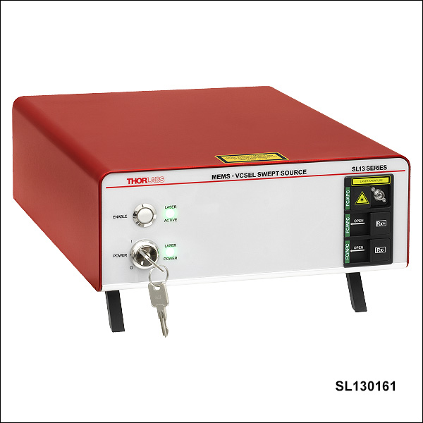
1300 nm SL Series MEMS-VCSEL Swept Sources
| Item #s | SL130160, SL130161 | SL131090, SL131091 | SL131160, SL131161 | SL132120, SL132121 | SL134050, SL134051 | |
|---|---|---|---|---|---|---|
| Sweep Rate | fMEMS | 50 kHz | 100 kHz | 100 kHz | 200 kHz | 400 kHz |
| Duty Cycle (Unidirectional Sweep) | DBOA | >60% | >60% | >60% | >50% | >50% |
| MZI Delay | ΔMZI | 72 mm | 44 mm | 72 mm | 32 mm | 12 mm |
| k-Clock Minimum Pointsa | Nmin | 4096 | 2496 | 4096 | 1792 | 640 |
| k-Clock Max Frequency (Typical) | fclock | 500 MHz | 500 MHz | 900 MHz | 900 MHz | 900 MHz |
| Imaging Depth Range (Approximate) | Δzmax | 18 mm | 11 mm | 18 mm | 8 mm | 3 mm |
| Optical Specifications for 1300 nm SL Series Swept Sources | ||||
|---|---|---|---|---|
| Optical Specifications | Symbol | Minimum | Typical | Maximum |
| Center Wavelength | λc | 1280 nm | 1300 nm | 1320 nm |
| Wavelength Sweep Rangea (-10 dB) | Δλsweep | 95 nm | 100 nm | - |
| Average Output Power | Po | 20 mW | 25 mW | 30 mW |
| Coherence Length | LCoh | 100 mm | >1 m | - |
| Spectral Ripple Noise Suppression | dP | - | ≥50 dB | - |
| Relative Intensity Noise (RIN) | RINORTHO | - | - | 2% |
| λ Trigger Wavelength | - | 1295 nm | 1300 nm | 1305 nm |
| Output Fiber Numerical Aperture | NA | - | 0.09 | - |
| Laser Classification (IEC 60825-1:2014) | - | 1M | ||
1300 nm SLZ Series MEMS-VCSEL Swept Sources
| Item #s | SLZ1301 | SLZ1302 | ||||
|---|---|---|---|---|---|---|
| Parameter | Mode 1 | Mode 2 | Mode 3 | Mode 1 | Mode 2 | Mode 3 |
| Sweep Rate | 50 kHz | 200 kHz | 400 kHz | 100 kHz | 400 kHz | 1000 kHz |
| Duty Cycle (Unidirectional Sweep) | >60% | >60% | >50% | >60% | >50% | >40% |
| Minimum Wavelength Sweep (-10 dB)a,b | 95 nm | 95 nm | 95 nm | 95 nm | 95 nm | 33 nm |
| Typical Wavelength Sweep (-10 dB) | 100 nm | 100 nm | 100 nm | 100 nm | 100 nm | 38 nm |
| MZI Delay | 169 mm | 42 mm | 17.5 mm | 42 mm | 8.5 mm | 6 mm |
| k-Clock Max Frequency (Typical) | <1 GHz | <1 GHz | <1 GHz | <500 MHz | <500 MHz | <500 MHz |
| OCT Imaging Depth Rangec,d | 42.3 mm | 10.5 mm | 4.4 mm | 42.3 mm | 8.8 mm | 6.0 mm |
| Recommended Data Acquisition | k-Clocking | k-Clocking | k-Clocking | Dual Channel | Dual Channel | Dual Channel |
| Optical Specifications for 1300 nm SLZ Series Swept Sources | ||||
|---|---|---|---|---|
| Parameter | Symbol | Minimum | Typical | Maximum |
| Center Wavelength | λc | 1280 nm | 1300 nm | 1320 nm |
| Average Output Power | Po | 20 mW | 25 mW | - |
| Coherence Length | LCoh | 100 mm | >1 m | - |
| Relative Intensity Noise (RIN) | RINORTHO | - | - | 2% |
| λ Trigger Wavelength | - | 1295 nm | 1300 nm | 1305 nm |
| Output Fiber Numerical Aperture | NA | - | 0.09 | - |
| Laser Classification (IEC 60825-1:2014/A11:2021) |
- | 1M | ||
SL and SLZ Series MEMS-VCSEL Swept Sources Electrical and Physical Specifications
| SLZ Series Electrical Performance Specifications | |||
|---|---|---|---|
| Parameter | Minimum | Typical | Maximum |
| k-Clock "Dummy Clock" Frequency | - | 250 MHz | - |
| Digital k-Clock Amplitude | - | - | 1.0 Vpp |
| Analog k-Clock Amplitude | - | - | 0.8 Vpp |
| Electronic MZI Signal Adjustable Delay | 0 to 16.6 ns | ||
| Sweep Trigger Pulse Width (100 kHz Sweep Rate) | - | 450 ns | - |
| Sweep Trigger Output Type | LVTTL | ||
| λ Trigger Pulse Width (100 kHz Sweep Rate) | - | 750 ns | - |
| λ Trigger Output Type | LVTTL | ||
| RF Output | - | - | 2.0 Vpp |
| Monitor+ and Monitor- | 0 to 1.5 V | ||
| Laser Controller Start Delay | 5 s | - | 15 s |
| SL Series Electrical Performance Specifications | |||
|---|---|---|---|
| Parameter | Minimum | Typical | Maximum |
| k-Clock "Dummy Clock" Frequency | - | 250 MHz | - |
| Digital k-Clock Amplitude | - | - | 1.0 Vpp |
| Sweep Trigger Pulse Width (100 kHz Sweep Rate) | - | 350 ns | - |
| Sweep Trigger Rise Time | - | 0.6 ns | - |
| Sweep Trigger Output Type | LVTTL | ||
| λ Trigger Pulse Width (100 kHz Sweep Rate) | 25 ns | 50 ns | 75 ns |
| λ Trigger Rise Time | - | 0.6 ns | - |
| λ Trigger Output Type | LVTTL | ||
| Laser Controller Start Delay | 5 s | - | 15 s |
| Physical Specifications | ||
|---|---|---|
| Parameter | Minimum | Maximum |
| Main AC Voltage | 100 VAC | 250 VAC |
| Power Consumption | - | 45 W |
| Line Frequency | 50 Hz | 60 Hz |
| Operating Temperature | 10 °C | 35 °C |
| Storage Temperature | 0 °C | 50 °C |
| Relative Humidity | - | 85%, Non-Condensing |
This data reflects the typical performance of our SL and SLZ series MEMS-VCSEL swept sources and is presented for reference only. The guaranteed specifications for all models are shown in the Specs tab.
SL Series Optical Output


SLZ Series Optical Output
Click to Enlarge
Click Here to Download the Raw Data
Optical Output Spectra of the SLZ100x Swept Source for Wavelength Sweep Ranges of 38 nm, 74 nm, and 100 nm
Click to Enlarge
Click Here to Download the Raw Data
Optical Output Spectra of the SL130x Swept Source for Wavelength Sweep Ranges of 38 nm and 100 nm
Click to Enlarge
Schematic of MEMS-VCSEL Swept Source with Balanced Detection
*The balanced detector and its associated connections will not be present on item #s ending in 0.
Thorlabs' MEMS-VCSEL benchtop systems incorporate all the necessary drive electronics, temperature controllers, trigger signals, and optical isolators for easy operation and integration into any swept-source OCT system. These laser sources utilize a specially designed Mach-Zehnder Interferometer (MZI) "k-clock" that provides a digital output signal for triggering data acquisition. Additionally, the SLZ series laser sources are equipped with an analog clock output, which is the direct output of the MZI interference signal. This analog signal allows "Dual-Channel" data acquisition as an alternative to using the digital k-clock for data acquisition ("k-Clocking").
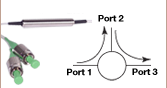
The figure to the right shows a schematic of the MEMS-VCSEL benchtop system. These systems consist of a MEMS-VCSEL cavity, a booster optical amplifier (BOA), a fiber-optic monitoring network, and signal generation circuits. The optical output of the MEMS-VCSEL cavity module is connected to the optical input of the BOA. Integrated optical isolators in the benchtop laser sources eliminate the need for additional isolators external to the laser. Three electrical output signals, shown at the bottom of the schematic, can be used via SMA connectors to synchronize a data acquisition system to the swept optical output.
Sweep Trigger
The Sweep Trigger provides an electronically generated LVTTL trigger pulse at the beginning of the sweep. The rising edge of the pulse is synchronized to the beginning of the sweep. The sweep trigger is generally used as a trigger for data acquisition systems. The signal is series terminated with 50 Ω.
Wavelength Trigger (λ Trigger)
"λ Trigger" is an optically generated LVTTL trigger pulse that indicates when the laser output has crossed a certain wavelength. This fiber-Bragg-grating-based optical trigger usually represents the middle of the sweep. Due to its higher wavelength stability, it is used as an alternative to the sweep trigger and can be used for phase-sensitive applications where sweep-to-sweep stability is required. The signal is series terminated with 50 Ω.
k-Clock
The k-clock signal is used as a data acquisition sampling clock, internally generated from an MZI. The digital output from the MZI "k-Clock" is linear in wavenumber, allowing optically generated signals to be sampled linearly in "k-space," rather than in the time domain. Electrically, the signal is an AC-coupled digital clock with an amplitude between 0.7 and 1.0 Vpp. During the back-scan, the k-clock circuit will switch over to a "dummy clock", which operates at a fixed frequency and is not correlated to the optical subsystem. The dummy clock runs at approximately 250 MHz.
Analog Clock (SLZ Series Only)
The analog clock signal is the direct output of the MZI interference signal, which is amplified to ±400 mV. The clock signal is only present during the forward sweep of the laser, corresponding to when the laser is actively emitting light. During the back-scan, no "dummy clock" signal is generated. The signal is impedance matched to a 50 Ω load for optimal transmission. This k-clock signal can be used for phase-stable acquisition techniques, where maintaining the phase integrity of the clock is crucial.
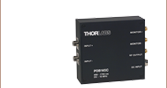
Balanced Detector (Not Included with SL1xxxx0 Sources)
The balanced detector (included with item #s ending in 1 and 2) consists of two well-matched photodiodes and an ultra-low-noise, high-speed transimpedance amplifier. This acts as a balanced receiver by subtracting Rx+ from Rx-, resulting in the cancellation of common mode noise. This produces an RF Output voltage that has small changes in the signal path extracted from the interfering noise floor. The optical input power level to each photodiode can be monitored through the Monitor+ and Monitor- fast monitor outputs.
Use the following links to view the SL or SLZ series device panels.
Note: The optical ports are intended to be connected to external measurement equipment with HI1060 optical fiber for the SL10 and SLZ10 sources, or with SMF-28 optical fiber for the SL13 and SLZ13 sources.
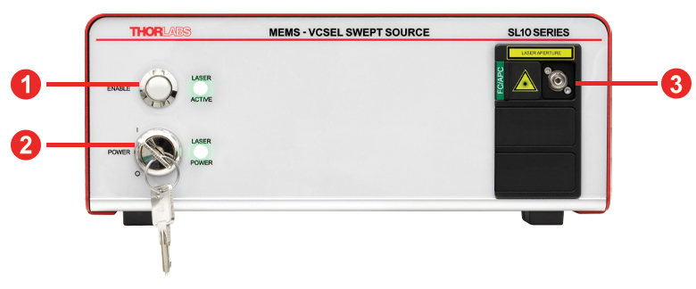
SL Series Front and Back Panels (without Balanced Detector, SL1xxxx0 Sources)
Click to Enlarge
Front Panel of SL Series MEMS-VCSEL Source

Click to Enlarge
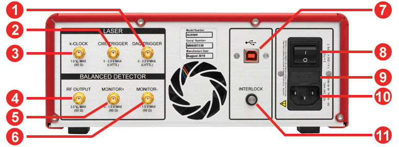
Back Panel of SL Series MEMS-VCSEL Source
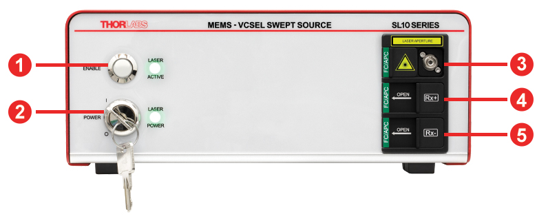
SL Series Front and Back Panels (with Balanced Detector, SL1xxxx1 Sources)
Click to Enlarge
Front Panel of SL Series MEMS-VCSEL Source with Balanced Detector
Click to Enlarge
Back Panel of SL Series MEMS-VCSEL Source with Balanced Detector
| Front Panel | |
|---|---|
| Callout | Description |
| 1 | Laser Enable Button |
| 2 | Laser Power Key Switch |
| 3a | Optical Output, 2.0 mm Narrow-Key FC/APC Connector |
| 4a | Rx+ Optical Input, 2.0 mm Narrow-Key FC/APC Connector |
| 5a | Rx- Optical Input, 2.0 mm Narrow-Key FC/APC Connector |
| Back Panel | |
|---|---|
| Callout | Description |
| 1 | Data Acquisition (DAQ) Trigger Signal (SMA Female) |
| 2 | Center Wavelength (CWL) Trigger Signal (SMA Female) |
| 3 | k-Clock Signal (SMA Female) |
| 4 | Balanced Detector RF Output Signal (SMA Female) |
| 5 | Balanced Detector Monitor+ (SMA Female) |
| 6 | Balanced Detector Monitor- (SMA Female) |
| 7 | USB Type-B Port |
| 8 | Main Power Switch |
| 9 | Fuse Holder |
| 10 | AC Power Cord Connector |
| 11 | Interlock Connector (2.5 mm Mono Phono Jack) |
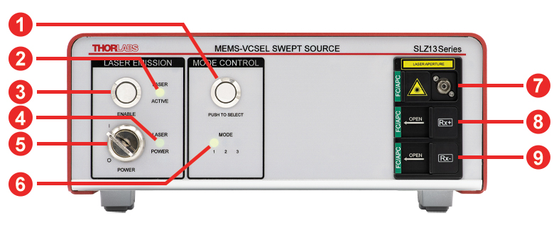
SLZ Series Front and Back Panels
Click to Enlarge
Front Panel of SLZ Series MEMS-VCSEL Source
Click to Enlarge
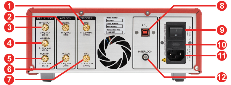
Back Panel of SLZ Series MEMS-VCSEL Source
| Front Panel | |
|---|---|
| Callout | Description |
| 1 | Mode Switch Button |
| 2 | "Laser Active" LED Indicator |
| 3 | Laser Enable Button |
| 4 | "Laser Power" LED Indicator |
| 5 | Laser Power Key Switch |
| 6 | "Laser Mode" LED Indicator |
| 7a | Optical Output Connector, 2.0 mm Narrow-Key FC/APC Connector |
| 8a | + Optical Input Connector for Balanced Detector, 2.0 mm Narrow-Key FC/APC Connector |
| 9a | - Optical Input Connector for Balanced Detector, 2.0 mm Narrow-Key FC/APC Connector |
| Back Panel | |
|---|---|
| Callout | Description |
| 1 | Data Acquisition (DAQ) Trigger Signal (SMA Female) |
| 2 | Digital k-Clock Signal (SMA Female) |
| 3 | Balanced Detector RF Output Signal (SMA Female) |
| 4 | Balanced Detector Monitor+ (SMA Female) |
| 5 | Balanced Detector Monitor- (SMA Female) |
| 6 | Analog k-Clock Signal (SMA Female) |
| 7 | Center Wavelength (CWL) Trigger Signal (SMA Female) |
| 8 | USB 2.0 Type-B Port |
| 9 | Main Power Switch |
| 10 | Fuse Holder |
| 11 | AC Power Cord Connector |
| 12 | Interlock Connector (2.5 mm Mono Phono Jack) |

MEMS-VCSEL Swept Source Utility GUI
Software
Version 2.3
This software package provides a GUI to control the MEMS-VCSEL Swept Sources.
![]()
MEMS-VCSEL Swept Source Utility
Thorlabs' MEMS-VCSEL laser sources can be fully controlled with the software package, which allows remote activation of the lasers and full control of module settings, such as MZI Delay and Optical Power. The three operating modes of the SLZ series sources can also be toggled using the software GUI. This software is provided on the USB thumb drive included with each device and is also available for download using the link to the right. This software requires a computer running Windows® 10 or 11 operating systems.
Thorlabs' MEMS-VCSEL Swept-Wavelength Laser Sources contain the following components:
- MEMS-VCSEL Laser Source
- USB Memory Stick (Includes Software, Manuals and Quick Start Guide)
- USB 2.0 Type-A to Type-B Cable, 2 m
- SMA Coaxial Cable, SMA Male to SMA Male, 2 m (Qty. 3)
- Keys (Qty. 2)
- Region-Specific Power Cord
- FBC250 Fiber Bulkhead and Connector Cleaner
- Printed Quick Start Guide
- 1A / 250 VAC Fuse, Slow Type (Qty. 2)
- Mode-ID Card (SLZ Series Only)
OCT Imaging with an SL Series MEMS-VCSEL Swept Source
OCT systems built using our MEMS-VCSEL sources provide high-quality images and are capable of significant imaging depths. The OCT cross-sectional image of the anterior eye shown below (left) was obtained using the equivalent of an SL131090 integrated into a Vega OCT system. The laser was swept over a wavelength range of 100 nm and had a 100 kHz sweep rate. This Vega system had a 44 mm MZI delay, an axial resolution in air better than 16 μm, and was capable of high-resolution imaging to a maximum depth of 11 mm. The OCT measurement signal was digitized with a 500 MSPS A/D converter, and the system provided 100 000 A-scans/s. Details of this system and its performance can be found here.
Point spread function (PSF) is a measurement of the optical performance of an imaging system, and narrower peaks indicate better performance. The PSF shown below (center) was obtained for the same Vega system as was used for the image to the left, but is typical of any OCT system using one of our swept-source lasers. For example, a system with an integrated SL101081 is shown to the right with similar performance, but with a maximum imaging depth of 6 mm.

Click to Enlarge
OCT Cross-Sectional Image of the Anterior Eye, from an OCT System
with Integrated SL13 MEMS-VCSEL Swept Source

Click to Enlarge
Click Here to Download the Raw Data
PSF Obtained for an OCT System with Integrated SL13 Series
MEMS-VCSEL Swept Source, Using Integrated k-Clock

Click to Enlarge
Click Here to Download the Raw Data
PSF Obtained for an OCT System with Integrated SL10 Series
MEMS-VCSEL Swept Source, Using Integrated k-Clock
OCT Imaging with an SLZ Series MEMS-VCSEL Swept Source
| OCT Imaging with the SLZ1001 Source | |||
|---|---|---|---|
| Parameter | Mode 1 | Mode 2 | Mode 3 |
| Sweep Rate | 50 kHz | 100 kHz | 400 kHz |
| Imaging Depth (Approximate) | 38.0 mm | 14.0 mm | 2.9 mm |
| Wavelength Sweep Range (-10 dB) | 74 nm | 100 nm | 100 nm |
| OCT Image of an Artificial Eye (Click for Image) | 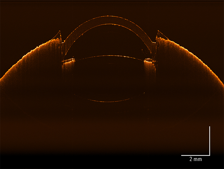 |
||
Each SLZ series laser source allows versatile imaging options when integrated into an OCT system. Each of the three predefined MZI configurations results in a distinct image acquistion rate and quality. The Sweep Rate, Imaging Depth Range, and Wavelength Sweep Range determine the acquisition speed, size (depth) of the imaged cross section, and axial OCT resolution, respectively. Swept Source OCT images of an artificial eye were generated using the SLZ1001 laser for each of the three MZI configurations ("Modes"). The table to the right shows the Mode 1, 2, and 3 parameters and the corresponding generated images. The Mode 1 image has the largest imaging depth, but lowest sweep rate and wavelength sweep range, resulting in an image of the whole eye with less axial OCT resolution. Mode 2 compromises some image depth for a faster sweep rate and the highest (100 nm) wavelength sweep range resulting in a medium sized sample image with the highest resolution. Mode 3 sacrifices image depth for acquisition speed while maintaining the highest resolution.

Click to Enlarge
Figure 1: Praevium's MEMS-Tunable VCSEL is an innovative design that offers high-speed and broadband emission with long coherence length. This is an ideal combination for an OCT swept laser source.

Click to Enlarge
Figure 2: MEMS-tunable VCSELs can be densely packed on a single wafer to increase the potential yield. The inset shows a single MEMS-tunable VCSEL device after fabrication. The overall size of the MEMS-tunable VCSEL is approximately 600 µm x 600 µm square.
VCSEL Overview
Vertical Cavity Surface Emitting Lasers (VCSELs) are semiconductor-based devices that emit light perpendicular to the chip surface, as shown in Figure 1. VCSELs were originally developed as low-cost, low-power alternatives to edge-emitting diodes, mainly for high-volume datacom applications. Quickly thereafter, the advantages of VCSELs became evident, leading them to being preferred light sources over edge-emitters in many applications. Compared to edge-emitting sources, VCSELs offer superior output beam quality and single mode operation.
MEMS-tunable VCSELs utilize microelectromechanical mirror systems (MEMS) to vary the cavity length of the laser, thereby tuning the output wavelength. MEMS-tunable VCSELs have existed for several years; however, the limited tuning range and output power of these devices have precluded them from being used in OCT applications. Praevium Research, in cooperation with Thorlabs and MIT, has since developed a MEMS-tunable VSCEL design that overcomes these previous limitations.
In order for a MEMS-tunable VCSEL to be successful for applications in OCT, it needs to meet certain standards:
- Rapid Sweep Speed
- Broad Tuning Range
- Long Coherence Length
- High Laser Output Power
Rapid Sweep Speed
Applications using OCT demand high-speed imaging without sacrificing imaging quality. Fast imaging rates allow better time resolution, dense collection of 3D datasets, and decreased laser exposure times to the sample.
Currently, there exist a few swept-source lasers that offer high-speed scanning. Fourier domain mode-locked lasers, for example, achieve extremely high imaging speeds but require the use of very long fiber optic delays in the laser cavity and can only operate in wavelength ranges where the fiber loss is low. Of the commercially available high-speed swept lasers, many operate with multiple longitudinal modes or have long cavity lengths, which limit coherence length or tuning speed, respectively.
The low mass of the MEMS-tuning mirror in a MEMS-based tunable VCSEL and the short cavity length both contribute to its high-speed operation. The short cavity length also places only one mode in the gain spectrum, enabling single-mode continuous operation. We have recently measured greater than 500 kHz sweep rates using a MEMS-tunable VCSEL prototype, without using optical multiplexing to increase the sweep speed.
Broad Tuning Range
High-resolution imaging depends on the overall tuning bandwidth of the swept-source laser. Praevium boasts the broadest bandwidth MEMS-tunable VCSEL that has ever been developed. A unique design incorporating broadband, fully oxidized mirrors, as well as wideband gain regions and thin active regions, has currently resulted in greater than 100 nm of continuous mode-hop-free tuning, centered around 1300 nm. For details, please see Figure 3.

Click to Enlarge
Figure 3: MEMS-tunable VCSELs are capable of tuning over 100 nm. Here we show single-mode operation over a 110 nm spectral tuning range centered at 1300 nm.

Click to Enlarge
Figure 4: Spectrum of MEMS-tunable VCSEL operating at 200 kHz, with a center wavelength around 1310 nm, and post amplification using a BOA.
Long Coherence Length
A significant limitation to most OCT systems is the depth of view (maximum imaging depth range). Especially in clinical applications, where sample thickness, patient motion, and sample location cannot be controlled, a long depth of view is advantageous. A long coherence length alone, however, is not enough. Image sensitivity needs to be virtually unaffected throughout the entire depth. Due to the micron-scale cavity length of the VCSEL and single mode, mode-hop-free operation, we have measured coherence lengths of greater than 100 mm from our MEMS-tunable VCSEL with nearly no signal degradation. Currently limited by detector bandwidth, we are confident that the MEMS-tunable VCSEL is able to achieve even longer imaging depths than have been measured to date. This remarkable depth of view will not only benefit the medical imaging community but also open doors to other applications such as large objective surface profiling, fast frequency domain reflectometry, and fast spectroscopic measurements with high spectral resolution.
High Output Power
Increased imaging speed often comes at the cost of decreased output power and/or optical power on the sample. One advantage of edge-emitting light sources over VCSELs is that they can emit greater output powers. As a general rule, most OCT imaging applications need a minimum of 20 mW of laser output power to maintain image quality when operating at faster scan rates. To reach this goal, the MEMS-tunable VCSEL is coupled with a booster optical amplifier (BOA) to achieve greater than 25 mW of power. An additional advantage of this post-amplification scheme is that the BOA reshapes the MEMS-VCSEL output spectrum such that it is much more uniform.
Additional Considerations and Manufacturing Capabilities
A special feature of the MEMS-tunable VCSEL is that it is scalable for different wavelengths. Through innovative combinations of gain materials and dielectric mirrors, a wide wavelength range in the visible or near infrared can be reached, enabling expansion of this new family of light sources.
As we further develop this light source, we look forward to finding new and exciting applications for its use. Please contact us to discuss how a MEMS-tunable VCSEL may advance your research.
Fabrication of a MEMS-Tunable VCSEL
Step 1
Click to Enlarge
The VCSEL wafer begins with a multiple quantum well (MQW) active region (A) that is grown on an InP substrate (B) and bonded to a GaAs-based mirror (C) grown on a GaAs substrate (D).
Step 2
Click to Enlarge
The InP substrate is chemically etched down to a strategically located stop-etch layer (E). The GaAs-based mirror is oxidized to create a wideband dielectric mirror (F).
Step 3
Click to Enlarge
After removal of the stop-etch layer, an AR coating (G) and annular MEMS bottom actuator contact (H) are deposited on top of the MQW active region.
Step 4
Click to Enlarge
A sacrificial layer (I) of a specifically designed thickness and composition is deposited.
Step 5
Click to Enlarge
A membrane layer (J) and annular top MEMS actuator contact (K) are deposited on top of the sacrificial layer.
Step 6
Click to Enlarge
Finally, a dielectric mirror (L) is deposited and patterned. The top MEMS contact is further patterned to complete creation of the actuator. The sacrificial layer is undercut to leave a suspended, moveable top mirror above the MQW structure, producing a VCSEL with a MEMS-based tuning element in a single device.
Laser Safety and Classification
Safe practices and proper usage of safety equipment should be taken into consideration when operating lasers. The eye is susceptible to injury, even from very low levels of laser light. Thorlabs offers a range of laser safety accessories that can be used to reduce the risk of accidents or injuries. Laser emission in the visible and near infrared spectral ranges has the greatest potential for retinal injury, as the cornea and lens are transparent to those wavelengths, and the lens can focus the laser energy onto the retina.
 |
 |
 |
 |
 |
 |
 |
 |
 |
Safe Practices and Light Safety Accessories
- Laser safety eyewear must be worn whenever working with Class 3 or 4 lasers.
- Regardless of laser class, Thorlabs recommends the use of laser safety eyewear whenever working with laser beams with non-negligible powers, since metallic tools such as screwdrivers can accidentally redirect a beam.
- Laser goggles designed for specific wavelengths should be clearly available near laser setups to protect the wearer from unintentional laser reflections.
- Goggles are marked with the wavelength range over which protection is afforded and the minimum optical density within that range.
- Laser Safety Curtains and Laser Safety Fabric shield other parts of the lab from high energy lasers.
- Blackout Materials can prevent direct or reflected light from leaving the experimental setup area.
- Thorlabs' Enclosure Systems can be used to contain optical setups to isolate or minimize laser hazards.
- A fiber-pigtailed laser should always be turned off before connecting it to or disconnecting it from another fiber, especially when the laser is at power levels above 10 mW.
- All beams should be terminated at the edge of the table, and laboratory doors should be closed whenever a laser is in use.
- Do not place laser beams at eye level.
- Carry out experiments on an optical table such that all laser beams travel horizontally.
- Remove unnecessary reflective items such as reflective jewelry (e.g., rings, watches, etc.) while working near the beam path.
- Be aware that lenses and other optical devices may reflect a portion of the incident beam from the front or rear surface.
- Operate a laser at the minimum power necessary for any operation.
- If possible, reduce the output power of a laser during alignment procedures.
- Use beam shutters and filters to reduce the beam power.
- Post appropriate warning signs or labels near laser setups or rooms.
- Use a laser sign with a lightbox if operating Class 3R or 4 lasers (i.e., lasers requiring the use of a safety interlock).
- Do not use Laser Viewing Cards in place of a proper Beam Trap.
Laser Classification
Lasers are categorized into different classes according to their ability to cause eye and other damage. The International Electrotechnical Commission (IEC) is a global organization that prepares and publishes international standards for all electrical, electronic, and related technologies. The IEC document 60825-1 outlines the safety of laser products. A description of each class of laser is given below:
| Class | Description | Warning Label |
|---|---|---|
| 1 | This class of laser is safe under all conditions of normal use, including use with optical instruments for intrabeam viewing. Lasers in this class do not emit radiation at levels that may cause injury during normal operation, and therefore the maximum permissible exposure (MPE) cannot be exceeded. Class 1 lasers can also include enclosed, high-power lasers where exposure to the radiation is not possible without opening or shutting down the laser. |  |
| 1M | Class 1M lasers are safe except when used in conjunction with optical components such as telescopes and microscopes. Lasers belonging to this class emit large-diameter or divergent beams, and the MPE cannot normally be exceeded unless focusing or imaging optics are used to narrow the beam. However, if the beam is refocused, the hazard may be increased and the class may be changed accordingly. |  |
| 2 | Class 2 lasers, which are limited to 1 mW of visible continuous-wave radiation, are safe because the blink reflex will limit the exposure in the eye to 0.25 seconds. This category only applies to visible radiation (400 - 700 nm). |  |
| 2M | Because of the blink reflex, this class of laser is classified as safe as long as the beam is not viewed through optical instruments. This laser class also applies to larger-diameter or diverging laser beams. |  |
| 3R | Class 3R lasers produce visible and invisible light that is hazardous under direct and specular-reflection viewing conditions. Eye injuries may occur if you directly view the beam, especially when using optical instruments. Lasers in this class are considered safe as long as they are handled with restricted beam viewing. The MPE can be exceeded with this class of laser; however, this presents a low risk level to injury. Visible, continuous-wave lasers in this class are limited to 5 mW of output power. |  |
| 3B | Class 3B lasers are hazardous to the eye if exposed directly. Diffuse reflections are usually not harmful, but may be when using higher-power Class 3B lasers. Safe handling of devices in this class includes wearing protective eyewear where direct viewing of the laser beam may occur. Lasers of this class must be equipped with a key switch and a safety interlock; moreover, laser safety signs should be used, such that the laser cannot be used without the safety light turning on. Laser products with power output near the upper range of Class 3B may also cause skin burns. |  |
| 4 | This class of laser may cause damage to the skin, and also to the eye, even from the viewing of diffuse reflections. These hazards may also apply to indirect or non-specular reflections of the beam, even from apparently matte surfaces. Great care must be taken when handling these lasers. They also represent a fire risk, because they may ignite combustible material. Class 4 lasers must be equipped with a key switch and a safety interlock. |  |
| All class 2 lasers (and higher) must display, in addition to the corresponding sign above, this triangular warning sign. |  |
|
| Posted Comments: | |
Zenaida Preston
(posted 2024-02-08 22:18:50.17) Wow, fantastic blog format! How lengthy have you been blogging
for? you make running a blog glance easy. The full look of your site is fantastic,
as well as the content material! You can see similar: Funero.shop and here Funero.shop dpossin
(posted 2024-02-09 04:53:11.0) Dear Zenaida,
Thank you very much for you positive feedback. We really appreciate that. Robert Zawadzki
(posted 2023-11-30 16:02:52.167) Dear Sirs,
I am interested in purchasing Thorlabs VCSEL 1050nm, Multimode, and MZI
CWL: 1050 nm
Sweep rate: 400 x 1, 200 x 2(400), 400x2 (800) kHz
MZI (air): 12, 24, 12 mm
High Power
Could you please send me the information about the pricing and options?
Best
Robert Yangxi Li
(posted 2023-10-13 12:30:31.06) Since I need to model the sensitivity roll off of the OCT system, I need to know the instantaneous linewidth of the swept source SL131090. Where can I query this parameter? Or how to calibrate it fmortaheb
(posted 2023-10-17 06:29:34.0) Thank you very much for contacting Thorlabs. In fact, the roll-off can be neglected for our swept source MEMS VCSEL lasers. The instantaneous linewidth is in the order of ~0.5 - 1.0 MHz corresponding to an estimated coherence length of 225m in air as shown within the following publication:
https://opg.optica.org/jlt/abstract.cfm?uri=jlt-33-16-3461 JUNG DAHUN
(posted 2023-03-09 18:50:00.627) Dear thorlabs
I am writing to inquire about direction of laser swept of SL132121
We have a SL132121 laser, but we don't know the direction of the laser's sweep.
Is it swept from the short wavelength to the long wavelength?
Thank you for your time and assistance. I look forward to hearing back from you soon.
Best regards,
Dahun Jung user
(posted 2023-03-01 11:43:21.173) Hi, I'm interested in this laser source, but I'm wondering if the short-wavelength cutoff could be pushed down to shorter wavelengths by a little bit with a little customization. Would it be possible to order a version capable of tuning from, for example, 1210 nm to 1300 nm? The long-wavelength cutoff only needs to be around 1280 nm for my application - it's more important to have short-wavelength reach for me. Let me know if this might be possible.
Thanks
Jeff SHUNAN CHEN
(posted 2022-06-15 11:21:09.337) Can I apply for a trail version of model.SL130161 or SL130160, I want to do some experiment to prove the light source is suitable for the experiment. Looking forward to your reply. wskopalik
(posted 2022-06-16 04:24:40.0) Thank you for your interest in our products. We will contact you directly to learn more about your needs to select the right configuration. Tomasz Kardaś
(posted 2020-10-07 10:41:15.827) Dear Sir or Madame,
We are looking for a source for Optical Frequency Domain Reflectometry near 1030 nm. Your sources seem perfect, however, they are much to fast for this technique. We look for something with 1 - 100 Hz sweep rate. Can you recommend any solution? nreusch
(posted 2020-10-09 06:14:39.0) Thank you for your feedback. We will contact you directly to discuss your application and possible solutions. nyonuimon
(posted 2018-09-04 18:57:59.367) Hello, This is Yeon Hee Chang
I am researcher of DGIST, South Korea.
I am very interested in the laser source, SL132120 - MEMS-VCSEL Swept Source, 1300 nm, 200 kHz.
I want to get a formal quotation of this product.
Is it available?
Please send the quotation to my e-mail.
Thank you :)
Best regards
From Yeon Hee Chang llamb
(posted 2018-09-05 08:17:04.0) Hello Yeon. For a formal quote or other questions on our MEMS-VCSEL Swept-Wavelength Laser Source, you may email OCT@thorlabs.com. We will have a representative reach out to you by email in this case. thomas.juhasz
(posted 2018-09-03 14:29:07.34) Hello,
I have a very basic question for the MEMS-VCSEL Swept-Wavelength Laser Source: has the source a static mode, where the wavelength is kept constant, or is the wavelength swept continuously? If there is a static mode, what is the wavelength accuracy and spectral linewidth for different wavelengths within the tuning range?
Additionally, the output power range from min 20 to max 50mW seems rahther large. Is a preselection with respect to the output power possible?
Thanks and best regards
Thomas YLohia
(posted 2018-09-24 11:00:16.0) Hello Thomas, thank you for contacting Thorlabs. The wavelength will be swept continuously for the entire range -- unfortunately, there is no static mode and there is no preselection with respect to output power. Our OCT team (oct@thorlabs.com) will reach out to you directly to discuss your application in greater detail. |

 Zoom
Zoom- Benchtop Swept-Wavelength Laser Sources with 1060 nm Center Wavelength
- SMA Outputs for Triggers and Digital k-Clock Signal Output
- Fixed Sweep Rates from 60 to 400 kHz
- Optional Balanced Photodetector
- Custom Source Configurations Available (Contact Our OCT Applications Team for Details)
| Item # | Sweep Rate | Duty Cyclea | MZI Delay | k-Clock Max Frequency (Typical) |
OCT Imaging Depth Rangeb |
Balanced Detectorc |
|---|---|---|---|---|---|---|
| SL100060 | 60 kHz | >60% | 48 mm | 500 MHz | 12 mm | None |
| SL100061 | PDB471C-AC | |||||
| SL101080 | 100 kHz | >60% | 24 mm | 500 MHz | 6 mm | None |
| SL101081 | PDB471C-AC | |||||
| SL101060 | 100 kHz | >60% | 48 mm | 900 MHz | 12 mm | None |
| SL101061 | PDB481C-AC | |||||
| SL102080 | 200 kHz | >50% | 24 mm | 900 MHz | 6 mm | None |
| SL102081 | PDB481C-AC | |||||
| SL104070 | 400 kHz | >50% | 8 mm | 900 MHz | 2 mm | None |
| SL104071 | PDB481C-AC |

 Zoom
Zoom- Benchtop Swept-Wavelength Laser Sources with 1060 nm Center Wavelength
- Three Selectable Operating Modes with Predefined Sweep Rate, Wavelength Sweep Range, and MZI Delay
- SMA Outputs for Triggers, Analog k-Clock, and Digital k-Clock
- Select Models Optimized for k-Clock or Dual-Channel Data Acquisition
- Integrated Balanced Photodetector
- Custom Source Configurations Available (Contact Our OCT Applications Team for Details)
| Item # | Sweep Rate | Duty Cyclea | MZI Delay | k-Clock Max Frequency (Typical) |
OCT Imaging Depth Rangeb,c |
Recommended Data Acquisition |
Balanced Detector | |
|---|---|---|---|---|---|---|---|---|
| SLZ1001 | Mode 1 | 50 kHz | >60% | 152 mm | <1 GHz | 38.0 mm | k-Clocking | PDB481C-AC |
| Mode 2 | 100 kHz | >60% | 56 mm | 14.0 mm | ||||
| Mode 3 | 400 kHz | >50% | 11.7 mm | 2.9 mm | ||||
| SLZ1002 | Mode 1 | 100 kHz | >60% | 28 mm | <500 MHz | 38 mm | Dual Channel | |
| Mode 2 | 400 kHz | >50% | 5.5 mm | 5.9 mm | ||||
| Mode 3 | 1 MHz | >40% | 4 mm | 4.0 mm | ||||

 Zoom
Zoom- Benchtop Swept-Wavelength Laser Sources with 1300 nm Center Wavelength
- SMA Outputs for Triggers and Digital k-Clock Signal Output
- Fixed Sweep Rates from 50 to 400 kHz
- Optional Balanced Photodetector
- Custom Source Configurations Available (Contact Our OCT Applications Team for Details)
| Item # | Sweep Rate | Duty Cyclea | MZI Delay | k-Clock Max Frequency (Typical) |
OCT Imaging Depth Rangeb |
Balanced Detectorc |
|---|---|---|---|---|---|---|
| SL130160 | 50 kHz | >60% | 72 mm | 500 MHz | 18 mm | None |
| SL130161 | PDB470C-AC | |||||
| SL131090 | 100 kHz | >60% | 44 mm | 500 MHz | 11 mm | None |
| SL131091 | PDB470C-AC | |||||
| SL131160 | 100 kHz | >60% | 72 mm | 900 MHz | 18 mm | None |
| SL131161 | PDB480C-AC | |||||
| SL132120 | 200 kHz | >50% | 32 mm | 900 MHz | 8 mm | None |
| SL132121 | PDB480C-AC | |||||
| SL134050 | 400 kHz | >50% | 12 mm | 900 MHz | 3 mm | None |
| SL134051 | PDB480C-AC |

 Zoom
Zoom- Benchtop Swept-Wavelength Laser Sources with 1300 nm Center Wavelength
- Three Selectable Operating Modes with Predefined Sweep Rate, Wavelength Sweep Range, and MZI Delay
- SMA Outputs for Triggers, Analog k-Clock, and Digital k-Clock
- Select Models Optimized for k-Clock or Dual-Channel Data Acquisition
- Integrated Balanced Photodetector
- Custom Source Configurations Available (Contact Our OCT Applications Team for Details)
| Item # | Sweep Rate | Duty Cyclea | MZI Delay | k-Clock Max Frequency (Typical) |
OCT Imaging Depth Rangeb,c |
Recommended Data Acquisition |
Balanced Detector | |
|---|---|---|---|---|---|---|---|---|
| SLZ1301 | Mode 1 | 50 kHz | >60% | 169 mm | <1 GHz | 42.3 mm | k-Clocking | PDB480C-AC |
| Mode 2 | 200 kHz | >60% | 42 mm | 10.5 mm | ||||
| Mode 3 | 400 kHz | >50% | 17.5 mm | 4.4 mm | ||||
| SLZ1302 | Mode 1 | 100 kHz | >60% | 42 mm | <500 MHz | 42.3 mm | Dual Channel | |
| Mode 2 | 400 kHz | >50% | 8.5 mm | 8.8 mm | ||||
| Mode 3 | 1 MHz | >40% | 6 mm | 6.0 mm | ||||